Effect of Na+ in situ doping on LiFePO4/C cathode material for lithium-ion batteries
Yan Liu,Wenchao Qin,Dengke Zhang,Liwei Feng,Lei Wu
School of Materials Science and Engineering,Shanghai Institute of Technology,Shanghai,200235,China
Keywords:Na doping LiFePO4 Cycling stability Rate capacity Cathode
ABSTRACT Li1-XNaXFePO4 (X=0,0.01 or 0.05) composite cathode materials were synthesized by the simple solvothermal method.SEM images showed that Na doping had little effect on the morphology of particles,which provided a guarantee for its excellent electrochemical performance.Charge/discharge data revealed that an appropriate amount of doped Na could improve electrochemical performance.Li0.99Na0.01FePO4 showed excellent rate capacity and cycle stability,i.e.,an extremely high keep in the capacity of 86.7%after 500 cycles at 10C,due to its ac facet morphology,larger lattice parameters in a and c,the enhanced electronic conductivity and Li-ion diffusion processes.
1.Introduction
Since the lithium-ion battery was launched by Sony Corporation of Japan in 1991,due to its small size,light weight and large energy density,it was widely used in the field of portable electronic products[1].With the promotion of new energy vehicles,high-performance lithium-ion batteries were the most promising power sources of electric vehicles [2,3].As the most promising cathode material for lithium-ion power batteries,LiFePO4(LFP)had attracted much attention because of its low cost,low toxicity and high thermal stability [4-6].
Unfortunately,LiFePO4also had apparent shortcomings,for example:at room temperature,the electronic conductivity (ca.10-9-10-10cm2S-1) and lithium-ion diffusion rate (10-14-10-16cm2s-1)were low [7,8],which seriously led to the poor electrochemical performance [9,10].Various methods had been introduced to overcome these problems [11-14].Among them,doping with isovalent cations was a very effective method.
Herein,we reported a concise strategy to fabricate LiFePO4samples by in situ polymerization reaction.The influence of the doping Na+on the structure,morphology and electrochemical performance of LiFePO4was discussed in detail.
2.Experiment
2.1.Synthesis of the cathode materials
FeSO4·7H2O,H3PO4,LiOH·H2O and NaNO3were uniformly mixed in the ratio of 1:1.5:2.7-X:X (X=0,0.01 or 0.05) to synthesize Li1-XNaX-FePO4.LiOH and NaNO3were dissolved in glycol for magnetic stirring.H3PO4solution was slowly dropped,and the white suspended matter appeared.Then FeSO4dissolved in glycol was added into the above white suspension and continuously stirring for 40 min,the precursor was transferred to a closed reactor with PTFE lining.The reactor was heated to 180°C in a constant temperature blast dried oven for 10 h,and then cooled to room temperature.Then the grey-green sediment was cleaned by distilled water and ethanol repeatedly,and dried at 80°C for 10 h.Polypropylene was mixed as a carbon source in LiFePO4,and then carbonized at 650°C for 3 h in Ar atmosphere to obtain the carbon coating.The samples with different sodium content x=0.01 and 0.05 mol were named as LFP-Na 01 and LFP-Na 05.
2.2.Structure and morphology characterization
The phase purities of the powders were analyzed by X-ray diffraction(TD 3500,Dandong)using Cu Kα radiation(V=40 kV,I=40 mA)with a 2 θ step-size from 10°to 70°at room temperature.The microstructure was characterized by scanning electron microscopy (SU 8220).The carbon contents of the powders were studied using a carbon-sulfur analyzer(HIR-944B).
2.3.Electrochemical characterization
The active material,acetylene black and polyvinylidene fluoride(PVDF)were mixed into a paste at a ratio of 80:10:10 wt,and then the paste was evenly coated on aluminum foil and dried in vacuum.The prepared cathode was assembled with a lithium metal anode,Celgard 3501 separator,and electrolyte(1 M LiPF6-EC/DM/EMC(1:1:1 v/v/v))into a CR 2016 button cell in a glove box with argon gas.The half-cells were charged and discharged in 2.0-4.2 V using the battery test system(LANHE CT 2001 A).The cyclic voltammetry and electrochemical impedance characteristics of the samples were studied with CHI 1000C and CHI 750 E,respectively.The cyclic voltammetric test was carried out with the two-electrode system,Li/Li+as the reference electrode,the scanning rate was 0.1 mV s-1.The amplitude of the electrochemical impedance test was under 5 mV and a 0.01-100 kHz range.
3.Results and discussion
Fig.1 showed the XRD patterns of the LFP,LFP-Na 01 and LFP-Na 05 samples.The position and intensity of each diffraction peak were in good agreement with the XRD pattern of LiFePO4(PDF#81-1173).The sharp peaks implied that all the samples were well crystalline,and the lattice structure of LiFePO4was not affected by a small amount of Na ion doping,the phase structure of NaFePO4was similar to that of LiFePO4[15].The lattice parameters of the three samples were shown in Table 1.As the amount of Na doping increased,the values a,c,andvof the LFP,LFP-Na 01 and LFP-Na 05 samples increased first and then decreased.Since Na+radius(0.97 Å)was larger than Li+radius(0.68 Å),LFP-Na 01 had a larger lattice size than LPF.LFP-Na 01 sample had a larger one-dimensional channel,which was beneficial to Li+intercalation/deintercalation[16].However,with the increase of Na doping,the structure of the formed LiFePO4will be changed and the a,c,and v values of samples decreased,which also proved by Liu et al.group[17].The change of the lattice consistently indicated that Na ions doped into LiFePO4phase.Lattice expansion provided more space for intercalation/deintercalation of lithium-ions[17].Also,when doped with Na ions,the lattice constant b was significantly reduced,which enhanced the intercalation/de-intercalation of lithium-ions and accelerated the diffusion rate of lithium-ions [18].

Table 1 Lattice parameters of the LFP,LFP-Na 01 and LFP-Na 05 samples.
The intensity ratio of I(020)/I(200) was generally applied to determine the preferred orientation of particles[19-21].I(020)/I(200)ratios of the LFP-Na 01,LFP-Na 05 and standard samples were 2.59,2.10 and 2.08,respectively,which indicated that LFP-Na 01 and LFP-Na 05 samples had ac facet morphology.
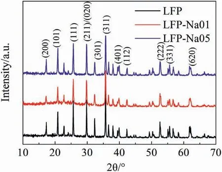
Fig.1.XRD patterns of the LFP,LFP-Na 01 and LFP-Na 05 samples.
Fig.2 showed the SEM images of the as-prepared LFP,LFP-Na 01 and LFP-Na 05 samples.From the scanning photos,it can be seen that the hydrothermal product particles had excellent dispersibility,the particles were uniform and subtle,the interface between the particles was clear,and the surface of the particles was smooth.Comparing the three photos,with the increase of doped Na ions,the morphological difference was not massive,and the particle size had not significantly changed between 200 and 500 nm.The agglomeration of particles with formed pores provided the channel for electrolyte penetration.The carbon coating limited the growth of particles,shortened the diffusion path of Li+,and increased the intercalation/deintercalation rate of Li ions [22].Na doping had little effect on particle morphology,which provided a guarantee for its excellent electrochemical performance.
Fig.3(a)showed the first charge/discharge profiles of the LFP,LFPNa 01 and LFP-Na 05 at 0.1C.The poor diffusion of lithium in the electrochemical reaction resulted in the voltage gap between the charging and discharging platforms [23-25].The initial discharge capacities of LFP,LFP-Na 01,and LFP-Na 05 are 158.5,156,and 151.7 mAh g-1,respectively.Meanwhile,the initial discharge capacities of the LFP-Na 01 and LFP-Na 05 electrodes were reduced.The possible reason was that Na+did not intercalate/deintercalate like Li+during the charge and discharge process,but stayed in the 4a position.The initial discharge capacity of the samples would reduce with the decrease of lithium-ion intercalation/deintercalation[15,26].
Fig.3(b)exhibited the rate cyclability of Li1-XNaXFePO4(X=0,0.01 or 0.05) cells from 0.1C to 10C.The LFP electrode showed the highest discharge capacity at a low discharge rate of 0.1C.LFP-Na 01 and LFPNa 05 showed superior rate capability than LFP at a more significant current density of 1,2,5 and 10C.The excellent rate capability of LFPNa 01 and LFP-Na 05 could be caused by the ac facet morphology mentioned above,meanwhile Na ion doping also decreased the migration energy barriers for Li ions [15].LFP-Na 01 had a better rate performance than LFP-Na 05 sample,especially at a high current density of 10C,the discharge capacity of LFP-Na 01 can still reach to 81 mAh g-1,while the LFP-Na 05 was only 74 mAh g-1.The decreasing discharge capacity of LFP-Na 05 could be caused by structure changing by doping too much Na+mentioned above.
Fig.4 showed the cycling performance curve of the LFP,LFP-Na 01 and LFP-Na 05 at 10C.Through aborative observation,we found that the first discharge capacity changed with the increasing of Na doping,followed by 64.4 mAh g-1,80.9 mAh g-1and 73.9 mAh g-1.After 500 cycles,the discharge capacity were 49.3 mAh g-1,70.1 mAh g-1,and 59.9 mAh g-1,and the capacity decayed rates were 23.4%,13.3%,and 18.9%,respectively.Maxish et al.[27] calculated the elastic properties of Lix-FePO4by the first principle and found that LixFePO4had a smaller shear modulus and higher anisotropy than other cathode materials,resulting in poor cycling performance of LixFePO4.After doping with Na+,Na+was less active than Li+.Na+maintained the 4a position and supported the one-dimensional channel,which made the crystal structure of the material stronger and the cycle performance was also improved[28-30].
Fig.5 displayed the CV curves of the LFP,LFP-Na 01 and LFP-Na 05 samples measured at 0.1 mV s-1.We could see that the symmetry of oxidation peak and reduction peak with the Fe2+/Fe3+redox couple reaction had good reversibility [31,32].Commonly,the potential difference(φp)of the redox peaks can be used to describe the reversibility of the material.The φpvalues of LFP,LFP-Na 01 and LFP-Na 05 were 416,336 and 349 mV,respectively.LFP-Na 01 displayed the smallest φpamount,which indicated that it had the best electrochemical activity and reversibility[33].Otherwise,the redox peaks of the LFP-Na 01 were higher redox currents than those of LFP-Na 05 sample,which meant that LFP-Na 01 sample had a higher intercalation capacity of Li+[34].
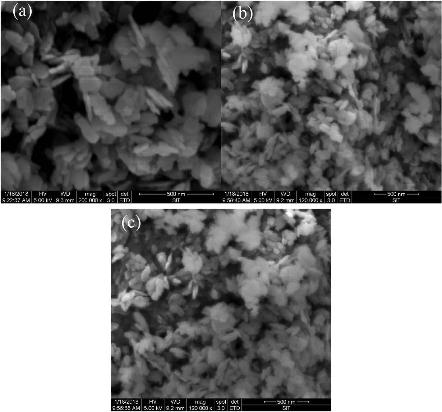
Fig.2.SEM images of the LFP,LFP-Na 01 and LFP-Na 05 samples.
Fig.6 illustrated the Nyquist plots of the LFP,LFP-Na 01 and LFP-Na 05 cathode materials.The equivalent circuit diagram was represented by illustrations.The impedance spectrum of all sample electrodes was composed of three parts:high-frequency region,intermediate frequency region and low-frequency region[35-38].Generally,the intercept of the Z′real axis high-frequency region corresponds to the ohmic resistance(Rs),which indicates the strength of the electrolyte and electrode material.The intermediate frequency semicircle represents the charge transfer resistance (Rct).Besides,the oblique line in the low-frequency region was related to the Warburg impedance (Zw) caused by the diffusion of lithium-ions in the electrode material [39-41].From the comparison of semicircle diameters,the impedance of the Na doped electrode decreased obviously,which showed that Na doping could effectively improve the conductivity of the electrode.Moreover,the slope of Na doped electrode in the low-frequency region was increased,which indicated that Na doping could effectively improve the mobility rate of lithium-ion [42,43].It was worth noting that according to the corresponding equivalent circuit model,the RCTfor LFP-Na 01 was 54.76 Ω,only a third of the RCT(175.9 Ω)for LFP,which indicated that the Na+could significantly improve the electron conduction of LiFePO4.As we all know,there was a close relationship between the charge transfer resistance and the electrode reaction kinetics.With the decrease of the charge transfer resistance,the electrode showed better kinetics performance [44,45].It was obvious that the LFP-Na 01 could provide excellent kinetic behavior,which was consistent with the above electrochemical measurements.
The relations between-Z′′and ω-1/2(the reciprocal square root of the angular frequency ω) for the LFP,LFP-Na 01 and LFP-Na 05 electrodes materials were shown in Fig.7.The lithium-ion diffusion coefficientcan be calculated according to the following equation[46,47]:
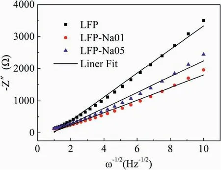
Fig.7.The relations between -Z′′and ω-1/2 for the LFP,LFP-Na 01 and LFP-Na 05 electrodes materials.

Where R was the gas constant,T was the absolute temperature.A was the electrode surface area,n was the number of reaction electrons,F was the Faraday constant,C was the concentration of Li+,was the Li+diffusion coefficient,σ was the Warburg coefficient,which had the relationship with Zreas formula (1);ω was the angular frequency.Therefore,according to formula (2),the diffusion coefficients of Li+in LFP,LFP-Na 01 and LFP-Na 05 can be calculated as 3.442×10-15,1.2325×10-14and 7.808×10⁻¹⁵cm2s-1,respectively,which indicated that the LFP-Na 01 could remarkably facilitate the Li-ion diffusion processes.The increase of the diffusion coefficient of Li+in Na-doped LiFePO4/C improved the Li+conductivity and the electrode reaction kinetics during the charge and discharge process,further reduced the internal electrode effect,and the rate of discharge performance was significantly improved [48,49].
4.Conclusions
In this work,the olivine structure LFP,LFP-Na 01 and LFP-Na 05 samples were synthesized via a conventional solvothermal method.Na+doping can improve the electrochemical performance of the LFP-Na 01 and LFP-Na 05 samples.Li0.99Na0.01FePO4/C discharge capacity retention ratio remained at 86.7%after 500 cycles at 10C,due to the crystal structure distortion caused by the doping of Na+.CV and EIS curves indicated the Li0·99Na0·01FePO4/C improved the Li+conductivity and showed the best electrochemical performance.
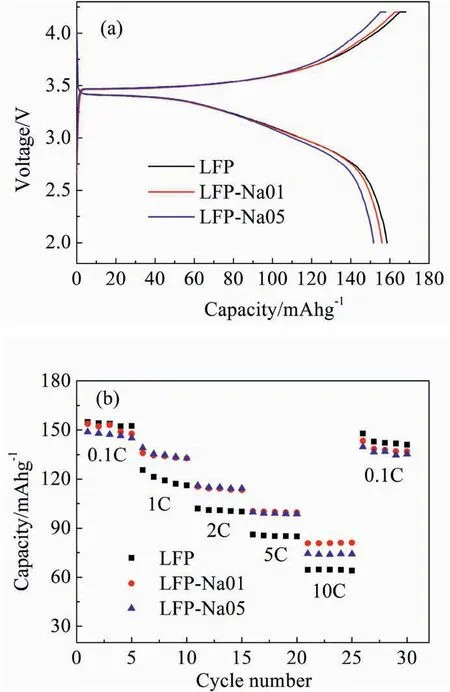
Fig.3.(a) First charge-discharge profiles at 0.1C,(b) Rate capability at 0.1,1,2,5 and 10C between 2.0 and 4.2 V for the LFP,LFP-Na 01 and LFP-Na 05 electrodes.
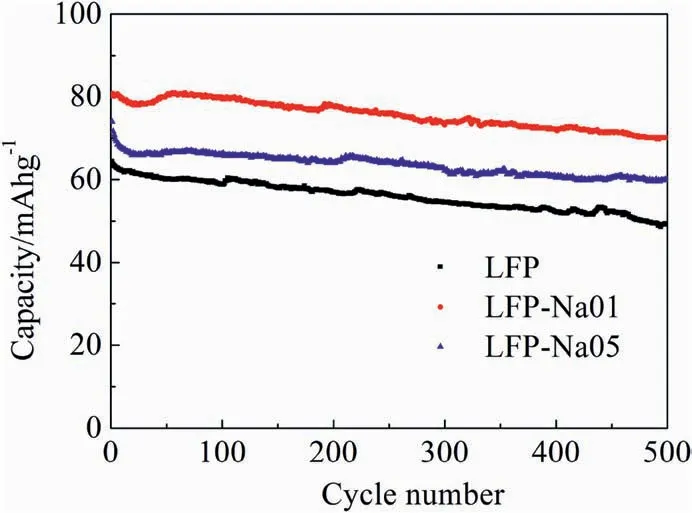
Fig.4.Cycling performances at 10C for the LFP,LFP-Na 01 and LFP-Na 05 electrodes.
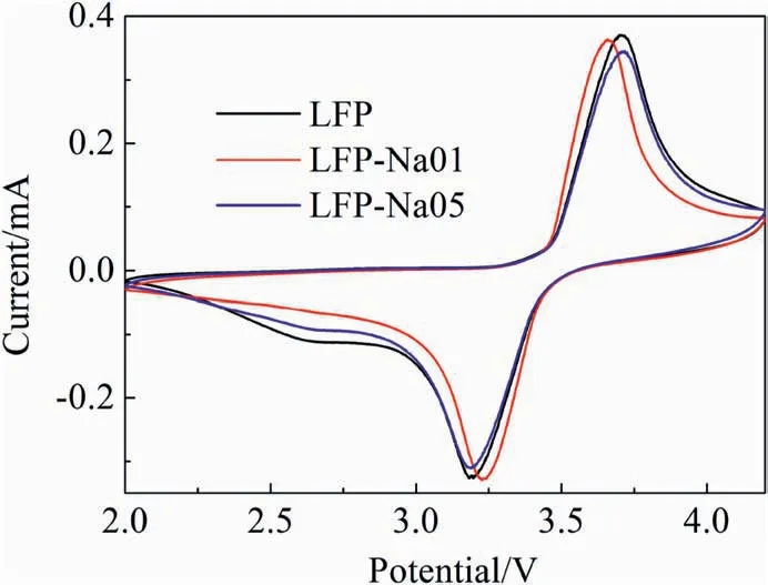
Fig.5.Typical cyclic voltammogram curves for the LFP,LFP-Na 01 and LFP-Na 05 electrodes.
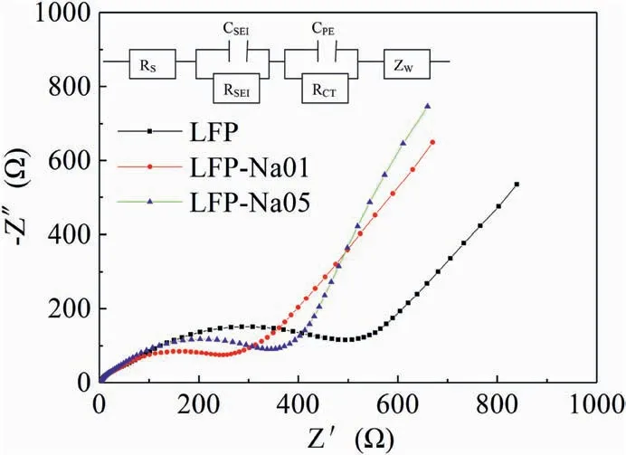
Fig.6.Electrochemical impedance spectra with corresponding equivalent circuit modle (inset) for the LFP,LFP-Na 01 and LFP-Na 05 electrodes.
Declaration of competing interest
The authors declare that they have no known competing financial interests or personal relationships that could have appeared to influence the work reported in this paper.
Appendix A.Supplementary data
Supplementary data to this article can be found online at https://doi.org/10.1016/j.pnsc.2020.10.006.
 Progress in Natural Science:Materials International2021年1期
- Progress in Natural Science:Materials International的其它文章
- Surface study of the reconstructed anatase TiO2 (001) surface
- Rational construction of NiCo2O4@Fe2O3 core-shell nanowire arrays for high-performance supercapacitors
- Electric transmission behavior of self-assembled Cu-W nano multilayers
- A hybrid hydrogel/textile composite as flame-resistant dress
- Improvement on hydrogen generation properties of Zr(BH4)4·8NH3
- A TEM study on the microstructure of spark plasma sintered ZrB2-based composite with nano-sized SiC dopant
