Comparative study of two lay-up sequence dispositions for flexible skin design of morphing leading edge
Yu YANG, Zhigang WANG, Shuaishuai LYU
Aircraft Strength Research Institute, Xi’an 710065, China
KEYWORDS Composite laminates;Flexible skin;Glass fiber reinforced plastics;Lay-up sequence;Leading edge;Morphing wing
Abstract Morphing leading edge has great potential for noise abatement and aerodynamic efficiency improvement. The drooping effect is realized by bending of the flexible skin which encloses to form the leading edge.Since the flexible skin is often made of composite laminates of Glass Fiber Reinforced Plastics (GFRP), the lay-up sequences have become the determinant, which affects not only the morphing quality but also the manufacturing complexity.Two optimizing methods of layup sequences are comparatively studied.In the first method,the laminal quantities in 0°,±45°and 90° vary independently, while in the second one, the concept of isotropic laminate unit[0/45/-45/90]s is employed and the unit quantity is the unique variable. Final evaluation demonstrates that for both methods there is insignificant impact to the overall morphing quality;however,specific concern is equally necessary for these two methods to the tip of the leading edge where the skin is at its minimum thickness and bears the most severe bending deformation. In terms of computational efficiency and post-processing labor, the second method has better performance.
1. Introduction
The morphing leading edge, featured with the characteristic that the enclosing skin remains in a continuous and smooth form during the deflecting process, has been studied for more than five decades. There are two main factors acting as the motivations of this study. One is for noise abatement.1Since the gap and slot introduced by the conventional high-lift system produce a large part of noise during takeoff and landing,to eliminate them is a good cause.The other is that the morphing leading edge would act as the basis for laminar flow wing,which claims a highly strict requirement of the skin surface quality.2–4
In the early days,like 1980 s,some prototypes of morphing leading edge had been proposed and tested. At that time, the drooping function is achieved by warping the aluminum skin at the leading edge with the actuation from internal mechanical kinematics.However,as everyone knows that considerable contraction will occur at the lower part of the leading edge when it droops, and common materials, like aluminum sheet,are unable to contract largely, the problem turns to the fact that there is no place for the contracted part to go.Therefore,some alternative solutions were proposed, such as a slot design,5which inevitably, however, deteriorates the structure stiffness as well as the surface quality.2The perfect solution is to develop such kind of skin which is featured with low inplane stiffness and high out-plane stiffness simultaneously.Related research has been carried out all along, and various innovative forms have been proposed, such as corrugated skin,6–9honeycomb core.10–13and shape-memory polymer composite.14–16However, due to unmatured material and manufacturing issues,none of these forms is put into practical use.
Interestingly,later investigation shows that the requirement of large contraction or tension on skin is unnecessary,and the drooping effect of morphing leading edge could be realized by pure bending of the skin while the circumferential length remains unchanged.2This profound finding was followed consistently as a core principle by all subsequent studies. And based on this principle, one of the most essential works is to design a flexible skin, simply supported at a few points by the inner kinematic mechanisms, with such proper thickness distribution that it can keep the required profile precisely in not only droop case but also clean case under respective aerodynamic load conditions, which presented no in-plane extension or compression.2
SmartLED2is the pioneering project,in which only 2D case was considered. A non-linear, gradient-based, unconstrained optimization method was developed for skin thickness distribution, and the associated skin fitness was evaluated through the Euclidian distance between the sampling points of the actually deformed and target curve. The skin was made of Glass Fiber Reinforced Plastics (GFRP) laminates, and supported and guided by internal lever-like kinematics to form the prescribed airfoil under different flight conditions. The omega shaped stringers connected skin and internal kinematics, of which the number and position were preliminarily studied.
The project SADE17acts as the successor to SmartLED,and a simplex search algorithm is developed for determining the optimal number and position of skin stringers,and 4 stringers were selected finally.
Further progress was made in Kintscher et al’s work in 2011.18The algorithm of skin thickness distribution combined the fruits of previous two projects by initializing the thickness distribution based on curvature change and optimizing it via the Lagarias’ simplex search method.19
Later on, the work on morphing leading edge in the SARISTU project mainly emphasized on some practical problems,such as deicing,anti-corrosion and lightning,and special birdcutting device design within the morphing part for bird striking.20
Meanwhile, there are a number of studies considering to replace internal actuating mechanism with compliant structure21–24or eccentric beam.25–29
The proper thickness distribution over the skin,that is, the proper bending stiffness distribution, only can be realized through dedicated optimization. Meanwhile, the most qualified material candidate at present is GFRP laminate. Therefore, the optimization result is presented in the form of a series of lay-up sequences along the skin profile. However, as the whole skin consists of a number of design zones and each laminate zone is usually made of dozens of laminate, it is impossible to obtain the exact lay-up sequence after optimizing process which is fit for manufacturing straightforward.Consequently, the post-processing work is more or less needed, and how much labor that is demanded depends entirely on the definition of the design variables at the very beginning of optimization. Nevertheless, one thing should be underlined that the basic rule of the lay-up sequence adjustment here is different from and more difficult than that of the common case. In general situations, people mainly concern about the in-plane mechanical properties of the laminate, which will not be affected by altering lay-up sequence, as long as the total plies are fixed. However, the scenario here is different. As the morphing effect of the leading edge is realized through skin bending, the variation of bending stiffness along the skin plays a significant role in morphing effect control. Therefore, when dealing with the practical manufacturing issues, an additional concern needs to be taken into account that the bending stiffness at each part of the skin should be kept unchanged in the uttermost from that of primitive lay-up sequence.
So far, there are few publications referring to the detailed description of lay-up sequence design of morphing leading edge. Two different strategies of lay-up sequence design are proposed in this paper, and the corresponding comparative study is made, which includes the influences on the morphing effect, the deviation of bending stiffness after post-process,as well as the convenience for lay-up sequence adjustment.We hope this paper will provide useful suggestions for flexible skin design using GFRP laminate in morphing leading edge.
2. Two strategies of design variable definition
2.1. Reference aircraft
The reference aircraft is the Aerodynamic Validation Model(AVM) presented by the Chinese Aeronautical Establishment(CAE).30It has a high-speed-ratio supercritical wing, rearfuselage mounted engines, and a T-tail31,32(Fig. 1). It is originally developed for a conceptual study of long-haul business jet and in-house CFD code validation. Later it is released as an open source model for calibration and adoption. The designed cruise speed is 0.85 Mach.The exact drooping profile of the morphing leading edge is obtained through a CFD analysis,assuming 17°drooping angle at the situation of 0.2 Mach and 14° attack angle. Since we only study the extruded 2D case, the corresponding airfoil section was selected at 30% in spanwise direction off the fuselage. The corresponding pressure distribution over the airfoil is presented in Fig. 2.

Fig. 1 Sketch of CAE-AVM.
The morphing leading edge consists of flexible skin, stringers,kinematic mechanism and actuator(Fig.3).The two ends of the flexible skin are attached to wing’s front spar,and stringers, in spanwise direction, are employed to transfer aerodynamic load to inner kinematic mechanisms.
2.2. Strategy of ply number Assignment (PNA)
2.2.1. Objective function
In the work presented in Ref. 17, the deformation quality was assessed by the Least Square Error(LSE)of coordinate difference over a number of monitoring points,as shown in Eq.(1).However, the LSE criterion may be insufficient since the final LSE can be low enough, although unacceptable deformation deviation arises in certain aerodynamically critical regime,such as the most front tip. Therefore, a weighted penalty is imposed to previous LSE algorithm, abbreviated as WLSE,for further refined deformation control.
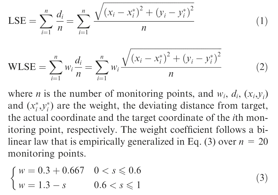
where s is the normalized length along the skin profile from the lower end to the upper.
2.2.2. Design variables
The design variables include lay-up sequence in each design zone, each stringer’s position and actuating force on each stringer.
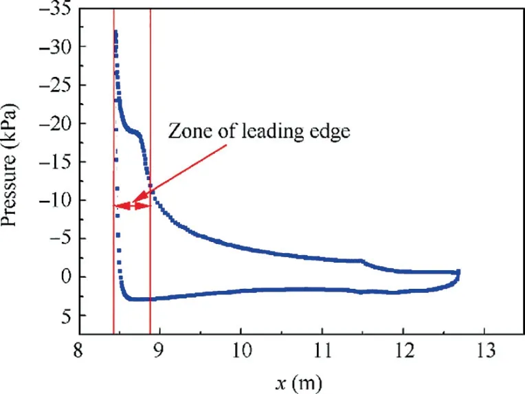
Fig. 2 Pressure distribution over the aerofoil.
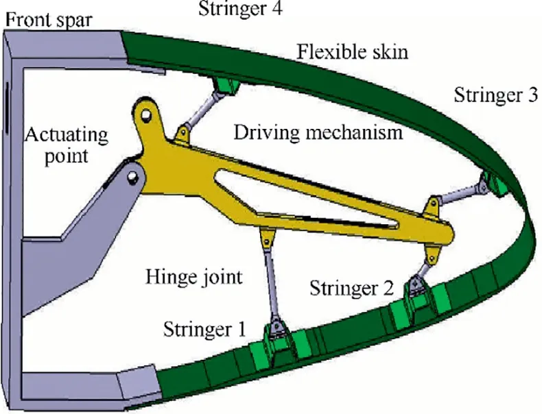
Fig. 3 Configuration of morphing leading edge.
The entire flexible skin is equally partitioned into 10 design areas (seen Fig. 4). In all design areas, they have uniform layup pattern [0a/45b/90c/-45d/90e]s, while a, b, c, d and e vary from one zone to another (0 aligns with circumferential direction of airfoil,and 90 with spanwise direction).The constraint of a to e is that they must be integrals.The lay-up sequence set here is not practical for manufacturing, although it is a compromise regarding computational efficiency and will be modified later in the post-processing. If practical lay-up sequence is taken into account firstly in the optimizing process, dozens of design variables will emerge in each design section alone,and the total amount will reach hundreds, which will deteriorate the computation significantly. Incidentally, the lay-up sequence of four stringers is set uniformly as[0/45/90/-45/-90-]s.
Furthermore, as mentioned above, the target deforming shape is realized through pure skin bending33and the circumferential length kept invariable during the morphing process.Based on this principle,the strains in the skin result from pure bending, and the relationship among the maximum strain at the outmost skin surface, the curvature and the thickness of the skin at that point is

where εlimis the material limit in terms of strain, s is the normalized length, t is the maximum allowable thickness, and Δk is the curvature variation. Both t and Δk are the function of s.
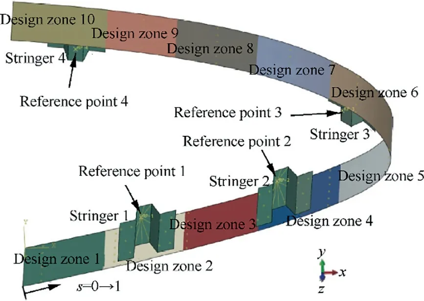
Fig. 4 Configuration of design zone partition and stringer positions.
The curvature k of deformed skin can be calculated by

where x and y are the horizontal and vertical coordinates of s,respectively.
Fig.5 shows the initial curvature(clean case),target curvature (droop case) and the curvature variation in between. The local maximum skin thickness is determined from Eq.(4) and then used as one of the constraints in the following skin stiffness distribution optimization process.For example,6511 high strength plain cloth prepreg is selected, of which the limit strain is 3.8%. Consequently, the maximum skin thickness at normalized length s of 42% and 50%, where the greatest curvature variation occurs, must be less than 3.5 mm, while the thickness constraint at other parts could be relatively less severe.
Four stringers can move freely along the skin profile during optimizing process. However, as thickness varies from one design zone to another, the issue depicted in Fig. 6 is highly likely to occur, where one flange would hover over skin when stringer strides over different skin thickness zones. Careless gap filler of adhesion or laminate materials after the optimization would obviously jeopardize the deformation quality.Therefore,it is necessary to address this issue in the first place,and the constraint is that both skin thicknesses underneath the two flanges of a stringer should be equivalent to each other.
2.2.3. Optimizing algorithm
It is known that conventional gradient-based optimization method and the Simplex method are not only inadequate for the current situation which requires collaborative optimization involving both continuous variables (the actuating loads) and discrete ones (the stiffness distribution over the entire flexible skin, the composite lay-up sequence, and the actuating positions), but also likely to be trapped in local optimal solutions.In contrast,the secondary generation of Non-dominated Sorting Genetic Algorithm (NSGA-II)34is known for its high efficiency and stability in terms of global optimal solution search,and the capability of multi-objective optimization. Therefore,NSGA-II is employed here, and the flowchart of entire working process is illustrated in Fig. 7. At the beginning when a generation of population of design variables(namely individuals) has been initialized, the main procedure will call the finite element module to generate the same amount of numerical models of morphing leading edge,each of which is customized with the corresponding design variables. All these models are analyzed to simulate the drooping deformation and its results are evaluated in terms of WLSE(namely the fitness valuation).Afterwards, the main procedure calls the NSGA module to update these design variables according to respective evaluation results, such as selection, crossover and mutation, and then to generate the offspring design variables. So far, one loop is finished and the same procedure above will be repeated until the convergence criterion is met.
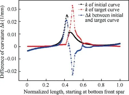
Fig.5 Initial curvature,target curvature and curvature variation along profile.
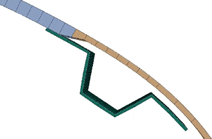
Fig. 6 Schematic of hovering flange of stringer.
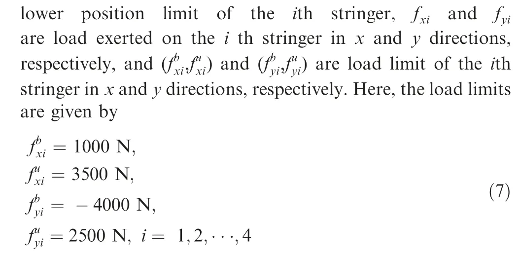
There are totally 62 design variables: 5 variables defining lay-up sequence in each of total 10 design zones; position of 4 stringers in terms of normalized length;actuating force components in x and y directions in each of total 4 actuating points. According to the recommendation from Ref. 34 that the population is expected 4 times larger than the design variable quantity, the population here is set 200. When variations of the optimal and average value in two consecutive generations are both less than 1.0×10⁻⁶, convergence is regarded to be achieved.
It is worth mentioning that non-linear finite element analysis(within right-hand side frame of Fig.7),rather than the linear one, has been employed to help produce movement locus of the actuating points on skin along optimizing process,which strongly supports later inner kinematic design,although it takes relatively longer computational time.
2.2.4. Finite element model
The skin and stringers are meshed with four-node shell elements of the order of 4.65 mm and 9.57 mm around.Stringers are adhered to skin through ‘‘tie” constraint. The upper and lower ends of skin are set to fixed constraint to simulate the connection to wing’s front bar in reality,and for each stringer,one reference point is set up to mimic the hinge joint linking inner kinematic mechanism and flexible skin.
2.2.5. Solution
Based on the above setting,we define the objective function as
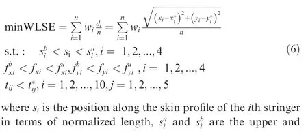
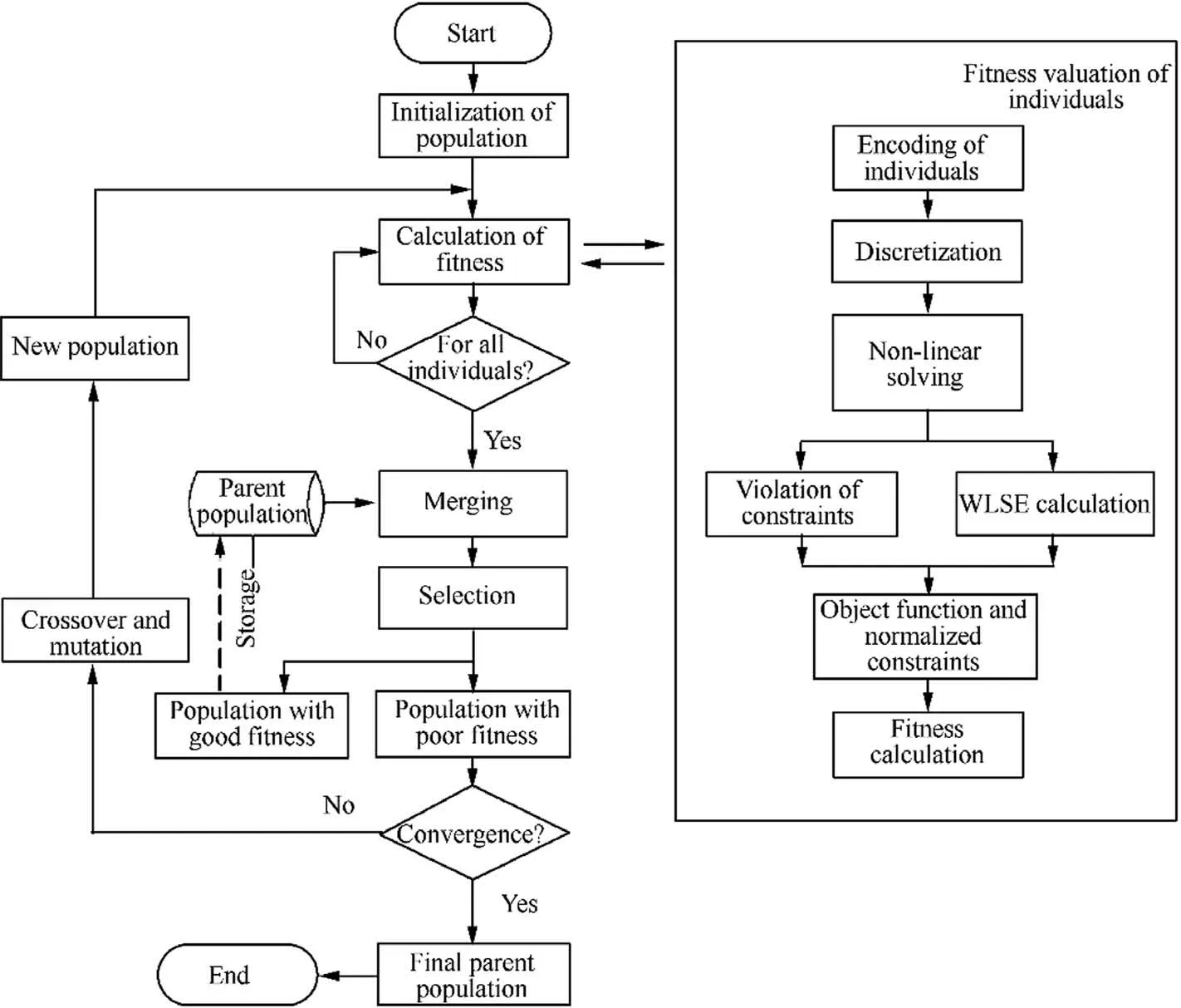
Fig. 7 Flowchart of compliant skin optimization based on NSGA-II.
2.3. Strategy of Quasi-Isotropic Unit (QIU)
There are two drawbacks of Ply Number Assignment (PNA)method. The first is that too many design variables are involved in the optimizing process,which will impair the computational efficiency. The other is that the optimized lay-up sequence is completely unable for laminate manufacturing.Here another method called Quasi-Isotropic Unit (QIU) is proposed.It is assumed that the skin is packed up with a number of quasi-isotropic sub-laminate units[0/45/-45/90]s,so the design variables a, b, c and d of each design area in PNA are now reduced to the number of the units in QIU. However, it is unjustifiable to limit the figure as an integral, because it is only in very special circumstances that the optimal laminate happens to be made up of integral times of the unit.As a solution, the decimal part of the optimized unit figure is switched back to equivalent number of laminae,which are scattered into the lay-ups.
As the main consideration here is of bending stiffness, the elastic properties of the unit used for optimization are derived according to theory of constrained cylindrical deformation.35–37For example,the Young’s module of the unit is expressed as

3. Comparative study
After the optimizing process, the results of thickness distribution over the skin, whether it be from either strategy, are obtained in terms of lay-up sequences. However, these ‘‘primitive” lay-up sequences need to be adjusted to some extent to meet the basic principle of laminate manufacturing.Obviously,heavier work is required for the one obtained through PNA strategy,in which all laminae in the same direction are stacked up together. According to the general principle, the ply number with the same direction should not be greater than three.Meanwhile, it has to be underlined again that during the adjustment process, not only the manufacturing practice of laminate but also the invariability of bending stiffness needs to be taken into account simultaneously.
Table 1 shows the adjustment results of each strategy, followed with the Bending Stiffness (BS) deviation produced.Fig. 8 depicts the bending stiffness distribution over total 10design areas before and after post processing, as well as stringer locations of each method.Because of the nature of genetic algorithm that result is hardly to be repeated in different optimizations, it is seen that the locations of stringer are different from one method to another; therefore, the bending stiffness distribution is also different. Fig. 8 reveals that the variation of bending stiffness after post processing averages at around 10%. However, combining the result presented in Figs. 9 and 10,we can find that the tip area of morphing leading edge(about 50% of circumferential length) is highly susceptible to bending stiffness variation,and any lay-up sequence alteration is largely influential due to two factors: first, this region bears the largest curvature alteration during the drooping process;second, the thickness there is the minimum.
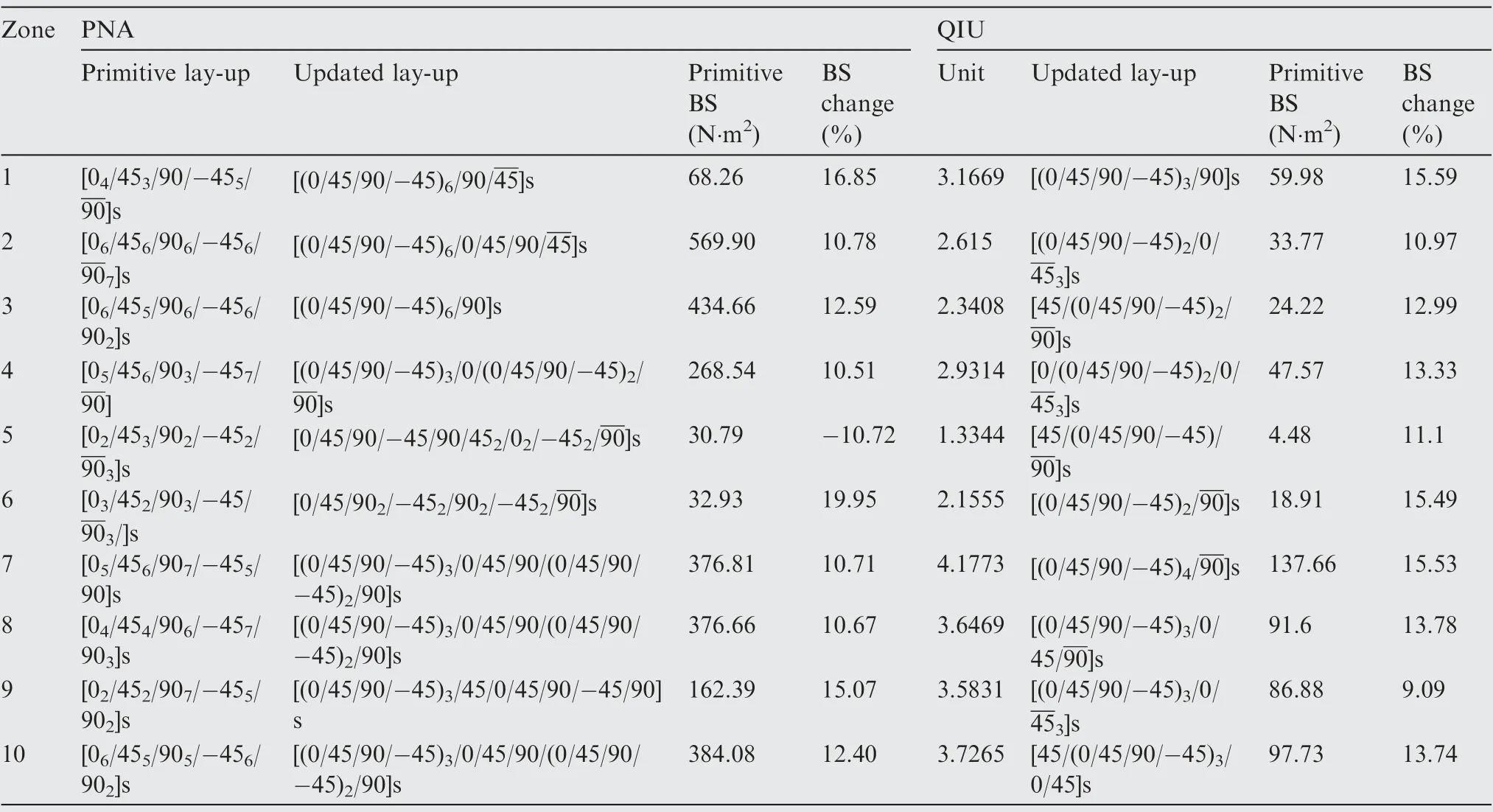
Table 1 Primitive and post-possessing lay-up for PNA and QIU.
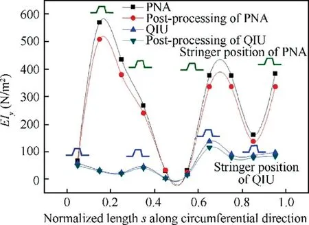
Fig. 8 Bending stiffness deviation from that of primitive lay-up for PNA and QIU along aerofoil profile.
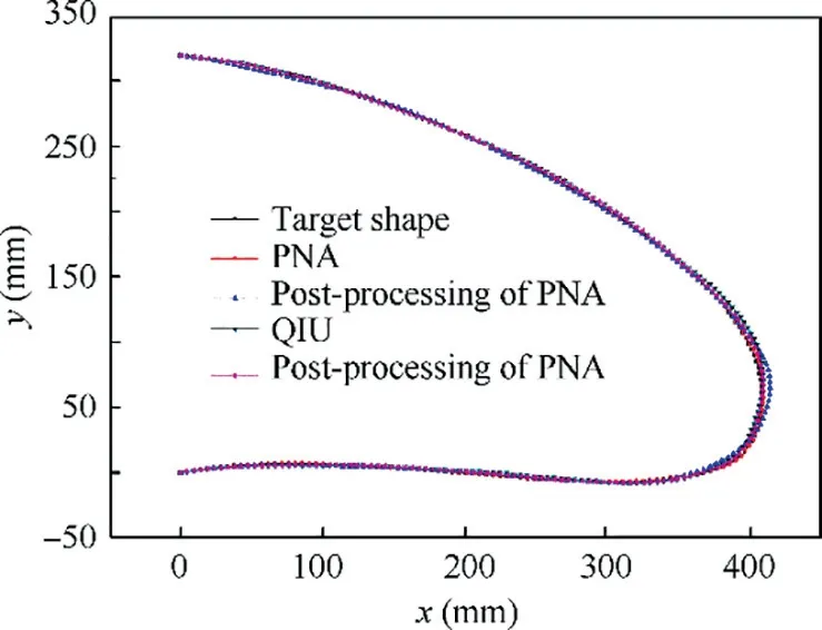
Fig. 9 Target profile and deformation profile of each method.
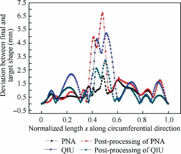
Fig. 10 Deviation of each method off target profile.
4. Conclusions
At present, the drooping effect of morphing leading edge is realized through pure skin bending which is actuated at only a few points, and GFRP is the most qualified material for the flexible skin laminate. Therefore, the dedicated design of proper bending stiffness distribution (in terms of lay-up sequence) along the skin profile is one key issue for morphing quality control.The setting of design variables of the skin laminate for the optimizing process will have profound impact to morphing effect as well as the post-processing work for skin laminate manufacturing.
Two design strategies of the flexible skin laminate are proposed. The main difference is that in the first one design variables are set for each group of laminae along the same fiber direction,while the other one employs the concepts of laminate unit. The flexible skin laminate consists of a number of such units, of which the mechanical properties are generalized over its all laminae.
Referring to the same aircraft,these two strategies as well as respective post-processing for manufacturable concern are employed. Through comparative study, it is concluded as follows:
• In terms of deforming accuracy, these two methods are within the same level;
• In both strategies, the lay-up sequence adjustment in postprocessing inevitably alters the original bending stiffness to a degree. This alteration has little impact to the thick and less deforming zones. However, it affects the tip of leading edge where the skin is thin and of severe bending,and consequently it has large impact on deformation quality;
• Better computational efficiency and less post-processing labor are required in the strategy of unit concept (QIU).
Declaration of Competing Interest
The authors declare that they have no known competing financial interests or personal relationships that could have appeared to influence the work reported in this paper.
 CHINESE JOURNAL OF AERONAUTICS2021年7期
- CHINESE JOURNAL OF AERONAUTICS的其它文章
- Integrated batteries layout and structural topology optimization for a solar-powered drone
- Polynomial networks based adaptive attitude tracking control for NSVs with input constraints and stochastic noises
- Morphing wing flaps for large civil aircraft:Evolution of a smart technology across the Clean Sky program
- Review on bio-inspired flight systems and bionic aerodynamics
- SARISTU:Adaptive Trailing Edge Device(ATED)design process review
- Continuous morphing trailing-edge wing concept based on multi-stable nanomaterial
