SARISTU:Adaptive Trailing Edge Device(ATED)design process review
A. CONCILIO, I. DIMINO, R. PECORA
a Department of Adaptive Structures, The Italian Aerospace Research Center (CIRA), via Maiorise, snc, Capua 81034, Italia
b Department of Industrial Engineering, Universita` di Napoli ‘‘Federico II”, Napoli 80138, Italia
KEYWORDS Actuator network;Aeroelasticity;Adaptive structures;Adaptive systems design;Adaptive trailing edge;Kinematic systems;Morphing;SARISTU;Sensor network;Skins
Abstract SARISTU was a big cooperation project granted by the European Commission, 7th Framework Programme, carried out between 2011 and 2015. It dealt with smart aeronautic structures,both morphing and sensored;its main target was to demonstrate the feasibility of designing,manufacturing and operating in representative environment, instrumented structures. Till now, it represents the major effort carried out within the European Union on the development of adaptive architectures for air systems. Inside that big activity, the realization of an Adaptive Trailing Edge Device (ATED) for wing camber adaptations aimed at compensating the weight reduction following the fuel consumption during cruise was addressed.It made the core of investigations target variable geometry aircraft components together with two other analyses concerning the development of shape-changing winglet and droop nose.ATED activities were conducted by the Italian Aerospace Research Centre (CIRA) in tight cooperation with the University of Napoli, ‘‘Federico II”, who coordinated a group of 12 different partners from 8 different nations (France, Germany, Greece,the Netherlands, Israel, Spain, Turkey,and Italy). In this paper,an integral synthesis of that work is reported,with a focus on the definition and realization of the components of the presented device.The publication is in fact meant as the first part of a series that is aimed at overviewing the whole adaptive trailing edge development, till wind tunnel tests execution. Such a concise report is a critical and harmonized review of what have been performed by many colleagues spread all over Europe, all of which are duly recalled in the reported bibliography where the reader may access more detailed information and descriptions.In detail,the paper starts with a general introduction of the concept and its aims, to move to the specs definition immediately after. Then, it deals with a short but comprehensive description of the main ATED components:structural skeleton,skin,actuation and sensing systems.It is worth remarking that the paragraph dedicated to the body frame includes some discussion about aeroelastic assessment and manufacture, seen as complementation for a complete assessment of the design constraints.
1. Introduction
Traditionally, flaps, ailerons, rudders and all the control and manoeuvring surfaces are used to modify the shape of aircraft wings (according to the principle that aerodynamics is geometry)and allow operations that are distinguished from the main mission, as cruise for commercial aircraft.1Indeed, conditions can vary a lot along and per single flight. An aircraft can be used for long or short-range transportation and can be at its Maximum Take-Off Weight (MTOW) or almost completely empty but the necessary fuel. Trivially, the weight of a commercial aircraft can be subdivided in four almost equivalent parts: structure, avionics, kerosene and passengers; mass variation can therefore reach values up to 50%! As a result, optimal trim configurations may change significantly, even for indirect contributions due to other associated consequences like the centre of gravity shift.
Among different forms of outlines transformations that can be attained,airfoil camber morphing does seem more effective and easier to be implemented if compared, for instance, to thickness modifications.2,3Other fashionable alterations, like chord or span extension or contraction,4,5require sophisticated and highly invasive devices, whose complexity threats the entire benefit associated to their use. Be clear that apart from traditional movables, adaptive systems are already present on many aircraft as variable sweep wings (F14), droop fuselage nose (Concorde), and so on.6,7Mechanisms are also frequent for guaranteeing stowage in limited rooms like on aircraft-carriers;8in that case, usual applications are almost exclusively devoted to military systems while there can be found some recent developments in urban mobility.
Lately, the attention of the world scientific and technological community has been more and more diffused towards the development of solutions aimed at modifying the wing camber by embedded systems, based on the use of classical or smart actuators.9–11In literature, by now, a wide diversity of devices aimed at morphing is present,but none is still implemented on commercial aircraft. Yet, flight experiments were performed recently on a Gulfstream aircraft, within a study involving AFRL, NASA, and Flexsys among the others.12–14And,going back in time, many other examples may be found,taking as major examples the test campaign conducted on the F111,along the 1980s.15,16As the attention is shifted far in the past,it is surprising how this kind of idea has always accompanied flight designers,being some patents on‘‘morphing”dated back to 1910s.17,18All those different proposals are very similar but the implemented technology, anyway too heavy and bulky to be actually installed on real aircraft.19–23The introduction of the so-called smart materials,24,25capable to naturally transduce electrical or thermal input into mechanical output, for instance, and the development of compact ElectroMechanical Actuators (EMA) also in view of future allelectric aircraft26have paved the way to the actual feasibility of adaptive structural systems.
Currently, there are two main design solutions -leading to macroscopically different architectures- that have been internationally followed: kinematic and compliant systems,27,28basically dissimilar for the kind of action:the first acts on rigid body displacement(telescopic wings,chord augmentation,and so on),while the second acts on the structural strain.Kinematics may be classified as an evolutionary concept, moving from available systems and modified into compact layouts able to produce desired deformations within classic structural compounds.29Compliant schemes represent instead a more challenging idea and deal with renewing the complete inner structural body to design and produce elements born to be deformed.29–32Both of them shall answer the basic needs of the technology,for a long time show-stopper of their practical use.Among all,the most evident are:the capability of sustaining loads while being deformable (the so-called paradox of smart structures);33the peculiarity of having suitable modal characteristics in spite of exhibiting many more degrees of freedom and larger elasticity levels;34,35the possibility of ensuring adequate safety and robustness grades, in order to withstand the strict aircraft regulations.35–38There are many reasons for addressing the one or the other,but a discussion about this topic goes beyond the scope of this article, and focuses on the presentation of a wide study concerning the development of a kinematic morphing system, instead.
The most obvious possibility to produce camber morphing is to act on the trailing edge. It is the base on which flaps and ailerons designs have been developed and are currently used on practically every aircraft, to deeply modify aerodynamic wing characteristics and allow affording flight conditions very different from cruise like take-off, landing and general manoeuvres. For flaps, the basic goal is to increment wing camber and so to increase its max lift and permit the plane to leave the ground while moving at low speed. A similar concept may be implemented in cruise. In fact, as an aircraft travels,its weight diminishes as a consequence of the fuel consumption, and the necessary lift for a ‘‘levelled” flight decreases.In turn, that occurrence makes the working point move along the polar (the classical function linking lift and drag)far from the targeted ‘‘optimal” condition (min drag, max efficiency –CL/CD, or any other). However, if the camber is modifiable,a new wing shape substitutes the former and a novel polar can be referenced, characterized by a new best design point.Camber variations may therefore compensate weight changes.
How large should that modification be? It was demonstrated39that a 10% Mean Aerodynamic Chord (MAC) variation can be sufficient to address the scope, if combined with deflections ranging in the interval ±5° That result gives the first reference measure at 30 cm chord for a 3 m MAC wing(roughly, a wing with a 5 m chord at the root and 1 m at the tip, the winglet being not considered). Moreover, it was also demonstrated that a single-segment morphing trailing edge has an effectiveness nearly equal to the half of a quasicontinuous camber variation device,40,41and that a threesegmented system is enough to approximate the curvature.In other words, a parabolic curve is adequate to replicate a generic aerodynamic shape within that domain,fitted for optimizing the desired curves bundle.A large numerical campaign conducted by the Politecnico di Milano, together with Leonardo Aircraft (former Alenia Aermacchi), confirmed those numbers for a deformable trailing edge aimed at maximizing the efficiency in cruise of a medium passenger aircraft, 3 h autonomy, Ma=0.75 cruise velocity and 60 t MTOW.42On those bases, an international group led by CIRA, and with the strong support of the University of Napoli ‘‘Federico II”, designed, manufactured and installed a full-size Adaptive Trailing Edge Device (ATED) on a 5.5 m long experimental wing section, which was successfully tested in the TsAGI T-101 wind tunnel.43Those activities were carried out in the framework of SARISTU, a European-funded large industrial project led by Airbus and involving 64 partners distributed over 16 countries. This paper collects and resumes in a single publication the different steps that move from the specs formalisation to the executive design of the device,which still represents one of the most significant technological achievements obtained in the field of morphing structures during the last ten years, to the authors’ knowledge.
2. Concept
According to the considerations provided in Introduction,and with the target of equipping the reference aircraft with a device compensating weight variations,the working group decided to focus its attentions on the wing trailing edge,the most feasible segment to be morphed with minimal impacts on the whole structure. Both weight deviations linked to the initial pattern(no passengers and minimal fuel, up to MTOW), and following the aircraft operations (kerosene burnt) were considered.As a consequence, mass shift up to 50% (asymptotic limit for an aircraft with empty tanks and no passengers onboard), was pondered. Lift coefficient may accordingly vary by a factor 2 under even external conditions (for instance, no altitude shift), in turn meaning a change from several tenths to more than a unit. Though generally valid, these considerations needed to be specialized with respect to the reference aircraft.
In the mentioned study, a 3-hour autonomy commercial aircraft was investigated, with the objective of keeping the value of the lift-to-drag ratio at a maximum, irrespective of mass variations. That goal was achieved by making adaptive a suitable portion of the trailing edge so as to realize a suitable curvature adjustment. De facto, the local wing section was modified into many others, each characterized by a certain polar: in this way, it was possible to navigate among different airfoil characteristics to keep stationary the efficiency. The architecture selected to enable such a shape transition was based on a finger-like layout:a rib made of four hinged blocks,the first of which was attached almost rigidly to the main structure. It allowed replicating a general curve (within a certain tolerance) in the same way that a three-bone finger can follow an arbitrary line.
A constant chord system was then deployed along the trailing edge, considering both the inner and outer regions (before and after the ‘‘kink”, i.e. where the wing rearmost border changes its line). Such a choice was mainly driven by reasons concerning architectural and manufacturing simplicity.A schematic representation of the device outline is reported in Fig. 1(a), highlighting the portion characterized by camber morphing capabilities.
It is worth mentioning that the finger-like architecture of each rib represented a Single Degree Of Freedom(SDOF)system, as shown in Fig. 1(b), being any rib block (B0-B3) connected to the adjacent ones by hinges and links (L1, L2) that ensured a proper movement transmission along the kinematic chain. For each rib, a single rotational EMA was then installed, which transferred the motion to the central segment(B2) through a namely rigid crank. The actuator network was guided by a control system that transferred the inputs after information provided by a distributed strain sensor network,aimed at reconstructing the current shape of the morphing structure and then getting information about the command effectiveness.
Two different control logics were implemented,considering respectively the only action of the operator(feedforward),like in the case of a purely mechanical car steer,or an autonomous feedback depending on the difference between desired and actual (achieved) shape, which in turn affects the real aerodynamic effect,for instance.Taking advantage of intrinsic EMA properties, the system was designed to keep its configuration and its stiffness(or compliance)while morphing,so as to guarantee preservation of the assigned geometry even under the action of aerodynamic and other operational forces(generated by internal and external factors). In the realized arrangement,the actuators could work in both a synchronous and an independent mode, i.e. move as one to produce uniform curvature variations,or as a Multiple Degrees Of Freedom(MDOF)system to enforce a certain twist angle distribution along the span.In this study,only the first modality was examined,shifting the other one to future investigations.

Fig. 1 Morphing trailing edge planform dimensions and trailing edge rib mechanism.
The designated compound kinematic system was embodied within a deformable skin to ensure geometrical continuity and minimise aerodynamic interferences with sharp geometry variations. That coating consisted of a composite architecture alternating rigid and highly elastic elements located at the hinge positions. The overall adaptive trailing edge system was the object of accurate FE modelling to verify its static robustness with respect to the specified loads and evaluate its vibrational response, moving from modal analysis. In fact,the very complex structural skeleton, made of many more parts than an equivalent passive configuration (a very critical aspect for operations), was expected to arise issues concerning stress distribution and eigenvalues density because of the widely distributed forces network,and the augmented number of DOF,respectively.Dynamics in turn affected the aeroelastic behaviour for the increased architecture complexity, with particular impacts on the flutter velocity.On that aspect.a critical role was played by the stiffness of the single actuation devices,which influences the mode shapes appreciably.44There is a specific consequence of this statement: because the whole appliance includes many EMA, the possibility of failure (jamming or complete break) shall be generally considered,together with related impacts on aerodynamic and structural instabilities. A Failure-Hazard Analysis (FHA) was then required to figure out behaviour alterations related to different breakdown maps.
The accomplishment of all the above mentioned steps allowed starting with the system manufacture that showed some further peculiarities by itself. Without facing yet the problem of optimising the shape of the different components(topology studies,not herein dealt with45–47),and the opportunity of realizing at least some of those parts by advanced techniques (like ALM48,49), the main challenges were related to implementing strict tolerances for the kinematic array elements, and the unicity of each of them, turning the process in a very long phase. Assembly operations were performed with very specialized, purpose-built jigs and tools in order to properly manage variable-configuration structures. The main criticality was in fact to be able to keep the designed,reference shape during the installation of the single components. A favourable aftereffect of that was the system exhibited an intrinsic faculty of re-centring when installed on the main system (i.e. on the complete wing). Among the other issues, the integration procedure had to take into account the fitting of the actuator and sensor networks with the associated cables,something that was duly considered for both space and weight necessity. Lab tests were carried out according to the usual standards for common structures with the main exception of the need to replicate different load conditions for the many prescribed geometries that the morphing architecture was expected to achieve.Deviations of the attained versus designed shape were measured,consenting to estimate the actual effects of the external and internal forces on the geometrical outline.Control systems functionality verification needed separate and dedicated tests.
The final segment of the activities was concerned with the installation of the Adaptive Trailing Edge Device (ATED)over the reference (SARISTU) wing. Functional tests were then carried out to verify the system capability of performing the prescribed form modifications within the established range.Finally,the complete alar section underwent wind tunnel tests,whose main scope was to check its operational capacity of maintaining a certain shape under actual aerodynamic loads(shape enforcing),and to evaluate mutual influences of the different morphing devices (as cited before, a morphing droop nose, and an adaptive winglet were also present, realized by other international teams). In fact, because the variableshape wing was an isolated system,internal forces had to yield a null field(resultant equal to zero).Stresses were generated as a specific component deformed,and propagated then along the skeleton,straining the most exposed segments(i.e.the morphing parts).Procured data served also to appraise the discrepancies between achieved and expected foreseen aerodynamic performances, due to the inevitable dissimilarities between the actual (segmented, smoothened somehow by the stretchy skin) and the nominal shape profile (continuous surface).
3. Specifications
In order to properly address the design of an adaptive device and evaluate the actual possibility of installing it on a real aircraft,a reference vehicle was selected,whose main characteristics may be summarised as follows: 60 t MTOW, 30 t OEW,Macruise=0.78,3 m MAC.40–42It was equipped with an about 100 m2, 34 m span wing. It was assumed that the aircraft configuration guaranteed the absence of any aeroelastic instability over the flight envelope.Having stated the macroscopic objective of the research (maintaining an optimum aerodynamic effectiveness along the cruise), and the device enabling that desired attainment (adaptation of the trailing edge by a kinematic mechanism), the next step was to establish its preliminary size.
Having selected the wing region, it was almost trivial to think that the device should not have exceeded the chord percentage after the main rear spar or, otherwise, the flap dimensions (30% of the local chord and 80% of the wing span extension).For the sake of simplicity, it was decided to design an adaptive trailing edge with a constant chord. Imagining then a 5 m root chord and a 1 m tip chord, it followed that the chord maximum length should have been set at about 54 cm, meaning 18% MAC (1.8 m is the chord length at 80%span;therefore,30%chord means 54 cm long).Concerning the deflections,a material constraint was fixed,limiting the deformability of the target structure. Being 1% a practical value sustained by most materials,and imagining to go beyond that limit by the use of special adaptive compounds,max strain was finally established at 2.5%.Indeed,the necessity of repeating several cycles at that value was also considered, therefore taking into account fatigue behaviour especially in view of utilizing plastics or silicones. Typical wing section profiles have a triangular shape at the trailing edge,whose aspect ratio(height to length) is about 25%. Having set a bundle of quadratic curves as the targets for the morphing device, these data brought to ±5° deflections, compatible with bibliographical results,39reporting that such values can allow proper polar variation in cruise.
Having defined the general design constraints,aerodynamic performance and load computation were carried out for different morphing configurations. A dedicated procedure was implemented by the Politecnico di Milano, based on a proprietary parametric framework(PHORMA,Parametrical sHapes for aerOdynamic and stRuctural Modelling of Aircraft).50,51Thirteen flight conditions were investigated, representative of the most severe operational conditions expected on the aircraft. It is worth mentioning that each configuration should have been investigated for different shapes of the morphing device, leading in turn to different load contours and magnitudes.
In detail, analysis loops were first used to calculate the angle of attack coherent with the specific lift coefficient, CL,in turn leading to the assumed load factor(classically intended as the ratio between the resultant aerodynamic force and the aircraft gross weight). Target shapes of the morphing wing were then obtained by solving coupled aeroelastic problems aimed at defining the best outlines that matched the established requirements. In order to limit the study complexity, a flight conditions subset was extracted;for the other configurations, assessed forms and their strain characteristics were then simply verified under the corresponding prescribed conditions.Standing the aforementioned points, the investigation domain targeting the optimal trailing edge extension could be confined as follows:
(1) Hypotheses. Load condition: cruise; ATED deflection range: ±5°; max skin epsilon (strain): 2.5%; areas in spanwise direction: 2 (corresponding to the inboard and outboard wing, Fig. 1(a)).
(2) Configurations analysed.Span:about 60%or 80%(this last value included the aileron region); chord: no tapering, constant value equal to 20% or 10%MAC.
The choice of having a constant chord was aimed at preserving a certain simplicity in the design. Indeed, because the selected structure was not uniform along the span but presented a variable thickness and chord, for instance, option did not assure an invariable layout along the region considered. Already at this stage, it was understood that the project of an adaptive system would have certainly led to a significant increase of the architecture complexity.
It was then assumed to introduce shape variations along the wing-span through 8 different sections,driven separately;each of them would have then undergone a constant deflection,as a unique piece. For the generic segment, the chordwise morphing shape would have then been interpolated via piecewise cubic surfaces. This strategy is compatible with the basic idea of making up the adaptive structural system via a three-block kinematic chain series, according to a classical scheme known as‘‘finger-like”,i.e. made of hinge-connected portions like the human finger, finally attached to a ‘‘fixed” block. In the presented investigation, such a fixed block connected the rear wing spar and the deformable device.
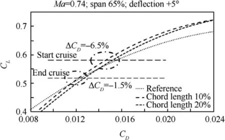
Fig. 2 Polar variation achieved by the activation of an ATED,PoliMI computations.40–42
The optimization problem allowed understanding what improvement could be actually achieved through the developed architecture, for the selected flight conditions. An example of those results is reported in Fig. 2, attained with CFD Euler-code computations,performed by the De Gaspari et al.50The example shows that the ATED was able to change the ratio CL/CDor,for a given CL,reduce the CDso as to increase efficiency or minimize drag.In detail,performances were evaluated by comparing the related polar curves for the analysed configurations.Displayed example reveals plainly how the larger adaptive flap causes a higher benefit over the reference polar, but it is the smaller one to give a better value in the observation region, correlated to a typical cruise mission. At different extent, this attitude was confirmed for all the analysed cases, under different patterns. The conclusion was that an outer wing morphing trailing edge extended for 10%MAC chord, and about 60% span, combined with an inner wing system extended for 20%MAC chord,could be preferred among the possible options, because it led to significant benefits while keeping its intrusiveness low. In other words, bigger apparatuses did not allow achieving gains so important to justify their massiveness.Such attainments would have been even smaller if the fuselage presence had been concerned about.
After these preliminary evaluations, aerodynamic achievements needed to be better assessed by taking into considerations other variables. In fact, since the addressed morphing framework acted to decrease the relative importance of resistance with respect to the bearing capacity, it was natural to pay more attention to dissipative terms and verify the results with viscous CFD codes outputs. Furthermore, because a deformable structure has more degrees of freedom than a traditional one, it does mean in itself that flexibility is increased;therefore,elastic deformation had to be necessarily considered.Such a complex problem was faced by ONERA that used a computational architecture based on their proprietary highfidelity CFD code elsA,40where the structure is modelled through FEM.
Conducted analyses allowed highlighting some peculiar aspects of the ATED behaviour mounted on the reference wing. Its deflection was shown to have a strong impact on off-design conditions, above all. This feature was particularly evident for large angles of attack (high-lift), when positive deflections of the device led to remarkable improvements of the efficiency(L/D).Surprisingly enough,chordwise dimension did affect the overall device performance only partially, even though the elastic response of the wing was drastically modified for the implementation of a more extended device.In some measure, the new outcomes did generally confirm the conclusions obtained with the previous Eulerian investigations.Once again, camber variations were verified to influence efficiency and hinge moments remarkably,in line with the comportment of a classic flap.
These indications strengthened and consolidated the architectural design.Being then available a complete configuration,and therefore the intimate characteristics of the overall structural system, it was possible to perform further analyses to understand how some schematic details could change the ultimate performance of the ATED. Target shapes, hinges position (relative and absolute), and absolute block length (even considering their spanwise distribution) were accounted for.It is worth remarking that such supplementary studies took place after the final morphing system configuration was defined;therefore,they could not feedback the design.At that stage, it seemed anyway necessary to understand at what extent several design choices could have changed concerned the final results, in order to have solid bases for successive developments. Those later studies were once more performed by ONERA through the already cited elsA CFD adjoint gradient solver, this time in combination with FFD72, a farfield post-processing tool. Generally, for high-lift, high speed conditions, efficiency increases between 1.5% and 3.5% could be expected, associated with 1–4 drag count reduction. Qualitatively, the situation is pictured in Fig. 3, where the potential benefit produced by an adaptive trailing edge in the region of maximum wing efficiency may be appreciated. Since that is precisely the wing design point, such numbers are very important, somehow stating how much the best performance was penalized in order to match other flight conditions need.Extensive details on these topics may be found in Refs.40,41,50,51
It can be of a certain interest in the end, to recall the basic optimization parameters and the general constraints of the proposed morphing device, and report what were the results of the preliminary aerodynamic investigation:
(1) Geometrical extension, 2D optimization – Chordwise extension was limited by the rear spar position (generally,at around 70%chord),while the spanwise direction was practically confined by the aileron region(generally at around 80%span);such a latter aerodynamic surface can be hard to be matched with adaptive requisites,even if some studies were performed about it.11,44
(2) Deflection, 1D optimization – For the envisaged application, the ideal physical range was ±90°, i.e. until tip backward movements were activated; because the system was constrained to remain within the wing section profile, that figure dropped drastically to about 10°–20°, depending on the architecture; that value affected the overall kinematic system design deeply.
(3) Hinge positions, 3D optimization – Spanwise direction was limited by the ribs layout (about half a meter step);thickness extension could not be completely explored because of the finite hinge size(a couple of centimetres),unless recurring to nacelles or other shielding solutions;chordwise positions should never lead to excessive differences among the articulated blocks size.
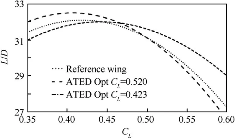
Fig. 3 Effect of ATED on efficiency and ONERA computations.40–42
(4) Shape,2D optimization–Namely,it appeared as a continuous optimization problem with infinite variables; in practice, however, it reduced because of: primary root constraints (necessity of ensuring continuity with the other part of the wing body at the rear spar); tip constraints (necessity to reach a 0-thickness or something close to that,at the airfoil extremity);geometrical limitations to parabolic curves,the reference layout consisting of N.3 movable blocks and N.3 hinges.
Assessed sizes:
(1) Geometrical extension: about 60% spanwise (corresponding to the flap region); uniform 10%MAC chordwise at the outer wing and 20%MAC at the inner wing,as shown in Fig. 1(a).
(2) Deflection: ±5° (consistent downward and upward movements).
(3) Hinge positions:almost uniform distribution chordwise,so that the three blocks resulted of equal length(considering that the ATED was about 36 cm long in the outboard wing region, each block resulted about 12 cm);regular distribution in the thickness direction, around the mean plane and therefore well inside the ATED body.
(4) Shape: parabolic.
4. Performance estimation
Former computations allowed carrying out a first estimation of the operational benefits expected by the ATED implementation in terms of increased range or reduced fuel consumption for the reference aircraft.40,41The base was given by the novel polar curves representing the behaviour of the namely infinite virtual profiles attained by a proper activation of the adaptive system at different angles, as shown in Fig. 2. Such an airfoil camber modification targeted to compensate weight reduction following fuel consumption. Having assumed that the only weight variation occurring on the airplane (dW) during cruise was due to the diminution of kerosene (dWf), being the fuel flow rate, F(t) is equal to

According to classical equations in levelled flight (constant velocity V, constant fuel flow rate, lift L equal to weight, and drag D equal to thrust T) for jet or propeller engines, respectively,and considering the travel range R equal to the integral of the elementary steps dS=V dt over the flight time, while dt=dW/F from Eq. (1), it followed:


where CTand Cpare the specific consumptions for trust and propeller motors in that order, ηjis the propeller efficiency,S is the wing surface, and ρ is the air density at the flight altitude. Then

Having made explicit the functional relationship between drag and lift coefficients, as appearing in the curves reported in Figs.2 and 3,in both cases,it could be finally written,standing the hypotheses above:

From Eq. (7), it was possible to evaluate range variations having fixed the available fuel (i.e. difference between initial and final weight) and take-off (or landing, alternatively) mass for the reference medium-range jet aircraft, or alternatively fuel savings having defined the target range. Finally, further assumptions were done, corresponding to an about 7 h mission:
(1) Max fuel: 15000 kg including reserve (constant,1200 kg).
(2) Max range: 3000 nm.
(3) Speed: 0.75 Ma @ 11000 m.
This formulation brought to interesting results,a short representation of which is reported in Table 1.40,41
As it can be seen, benefit was expected to increase as much as the configuration was far from the nominal design condition, in this case corresponding to a CLof around 0.4, as shown in Figs. 2 and 3.
Having in mind that the ATED was a 3-segment device, it looked of some interest to understand what would have been the effect of a plain non-slotted flap. Results are reported in Table 2,40,41together with the ratio between the two performances.
Predicted advantage was clear also in this case, but the mean profit fell to about a half with respect to the previous architecture, and was always lower than before but at a single point. Surprisingly enough, performance was in fact found to increase for very small loads (empty aircraft, minimum embarked fuel); that one remained an isolated point, worth to be further checked with advanced simulations. Potential range increase was also estimated;complete results are synthetically reported in Table 3.41
5. Structure
Preliminary structural design of aircraft components represents a complex process where several variables shall be taken in account to produce efficient layout, compliant with specific requirements as for conventional items:
(1) Capability of withstanding the most severe loads expected in service without failure or degradation of structural properties during the entire life-cycle (safety).
(2) Avoidance of unnecessary weight (fuel consumption).
(3) Simplicity of the overall layout for manufacturing and assembly purposes, as well as maintenance necessity(safety, operation).
When dealing with adaptive structures, complexity of preliminary design process naturally increases as a consequence of the augmented functionality of the system to be assessed.Among the other necessary targets, a morphing structure has to:
(1) Assure controlled and fully reversible transition from a baseline to a set of different geometries, withstanding characteristic external loads and stress distributions,complying with safety margins.
(2) Enable high-fidelity reproduction of target shapes under the action of aerodynamic and inertial loads.
(3) Avoid detrimental impacts on flight safety and overall aircraft maintenance plans.
In these paragraph, a thorough description of the approaches and methodologies implemented for the assessment of the morphing trailing edge structural layout is given,with particular emphasis to the rational justifications of the adopted solutions.52–55
Following the preliminary aerodynamic studies, ATED optimized shape was defined, along the regions of interest before and after the kink, for a total of 10 m span about.For the sake of simplicity, in this first phase, the chord length was assumed constant and equal to 10%MAC, resulting into 34 cm for the reference wing in the outboard region. Airfoilcamber morphing angle was defined so that the airfoil tip is thought to rotate around a virtual hinge located on airfoil camber line at the most forward chordwise position.The angle β(in this application,belonging to the interval±5°)is defined between the two straight lines joining the centre of rotation with the tip, in the non-morphed and morphed configuration,as shown in Fig. 4.29

Table 1 Fuel savings after the implementation of a 3-segment ATED.40,41

Table 2 Fuel savings after the implementation of an adaptive plain flap.40,41

Table 3 Summary of results for TE adaptation (3-segment versus plain).41
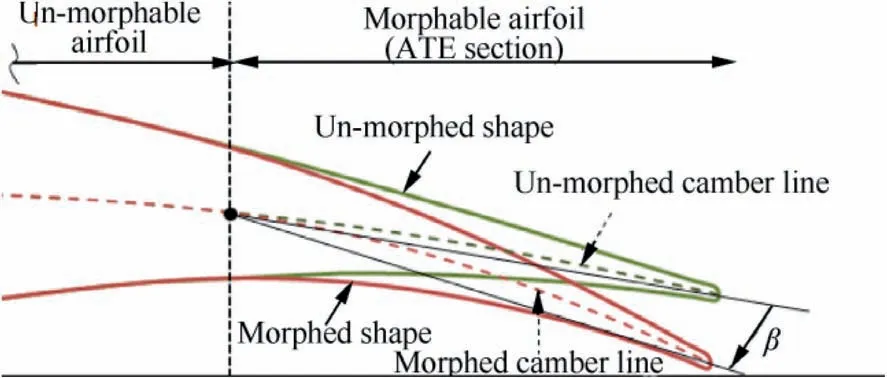
Fig. 4 Airfoil baseline and morphed shapes.29
In order to enable adaptive trailing edge morphing within the defined envelope, a special kinematic segmented concept was developed for its ribs, whose chordwise extension was maintained constant along the span.
The ribs were segmented into four consecutive blocks,named B0,B1,B2,and B3,hinged to each other at some specific points of the camber line A,B,and C,as shown in Fig.1(b).B0 was rigidly connected to the main wing structure and represented the section spanning from the rear spar to the movable parts. It was usually referred to as ‘‘dead block”.Non-adjacent blocks were finally connected two by two by means of stiff beams(L1 and L2)in turn hinged on the related segments. In this way, the four pieces made an articulated chain of consecutive segments forced to rotate according to specific gear ratios, generating a single degree-of-freedom system: if an actuator had moved any of the blocks (in that case,B2),all the others would have followed the movement accordingly, as shown in Fig. 5. It is worth remarking that this kind of architecture implied the reference to load-bearing actuation chains, meaning that driving devices absorb a significant part of the loads. The mechanism layout was designed to amplify rotations of its components so that little spin of the actuated block was sufficient to produce large rotations of the overall segmented system;large shape changes could then be obtained by reducing actuator strokes.Therefore,size and weight of the actuator system could be maintained conveniently low.
Such an architecture used then a 3-segment polygonal line to approximate the ideal shape of the ATED.Further aerodynamic computations and considerations would have then been necessary to evaluate the difference between the performance of the nominal and actually implemented airfoil shapes. That kinematic solution was preferred to a compliant architecture since the aerodynamic benefits associated to continuous and smoother curves would have outweighed by the drawbacks related to its practical implementation, basically related to the intrinsic nature of flexural pivots; for instance, they:
(1) Shall have a limited range of motion in turn defined by stress limitations; a larger number of elastic points would have been then necessary to accommodate the specifications, finally leading to a more complex and expansive arrangement.
(2) Have hardly-controllable behaviour when subjected to multi-axis loading; they can twist under torsion loads and exhibit shear deformations under homologues loads: in other terms, elasticity is a property that is difficult to make orthotropic; in contrast, revolute joints may be almost assumed rigid but around the desired axis.
(3) Introduce further mechanical resistance to the actuators action, because they involve structural deformations,further to the external loads.
Coherently with the hypothesis of having a constant ATED chord along the span of the referred wing region,the length of B1,B2,and B3 was considered the same for all the active ribs.B0 extension was instead determined by the complement to the rear spar case by case, according to the existing taper. Hinges connecting various blocks were placed along the camber line so as to follow the given shape envelope at the best.
Link fulcra were the unknown variables to be determined in the assumed reference system in the rib plane,generating therefore 8 variables. Referring to schematic and symbols reported in Fig.5,the mathematical formulation consisted in finding the 8-component vector v=[xLij,zLij],where‘‘i”is the index identifying the link (1 or 2)and ‘‘j” is the index pointing at its terminations (1 or 2), satisfying both the equations:
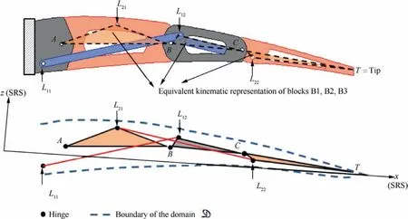
Fig. 5 Finger-like segmented rib, conceptual scheme9.

This process allowed evaluating the locus of the variables L11and L21, compatible with the assigned L12and L22. A graphical representation of what can be the aspect of the related hinges locus is reported in Fig.6.The optimal position of the hinges Lijwas in the end determined after practical considerations, taking into account the actual feasibility of the mechanism.
In detail, a maximizing merit figure was defined including two distance parameters: from the camber line (to avoid dangerous links alignment), and from the closest airfoil boundary(to avoid mechanical interferences with the skin panels).
The described procedure could be applied to each active rib in order to match at the best the target morphed camber lines, at the different spanwise sections. Ribs were then considered independent mechanisms designed with the sole purpose of respecting geometrical specifications. Such a choice however resulted in main drawbacks when individual kinematics were assembled into a unique adaptive box as:
(1) Spanwise hinge lines resulted non-continuous (segmented line), non-perpendicular to sections planes, and non-parallel to the trailing edge line, with dramatic impacts on the overall kinematics.
(2) Because different sections of the ATE resulted are characterized by different mechanisms, each of them should have driven differently and synchronously, with serious impact in terms of architecture complexity and reliability.
In order to overcome these absolute complications, hinges were repositioned according to the following guidelines:
(1) Locations of hinges placed at the ATED mid-span section were defined according to the illustrated methodology.
(2) Locations of other hinges placed at the generic section were obtained by projecting the above positions perpendicularly to the related mid-span plane.
This operation led to:
(1) The same mechanism for all the active ribs.

Fig. 6 Locus of hinge positions for adaptive rib mechanical system.
(2) Hinge lines normal to rib planes and parallel to trailing edge line.
(3) Morphing geometry compliant to target morphed shapes at the ATED mid-span.
It was then verified that deviation of the overall morphing camber lines was negligible with respect to the ones specified by aerodynamic studies.
The defined kinematics was implemented to the ATED structure through a multi-box arrangement. Each cell was defined as the volume delimited by homologue and consecutive rib segments spanwise,and by longitudinal spars chordwise.A visual schematic representation of that concept is reported in Fig. 7, for a generic bay, intended as the ATED portion between two adjacent ribs.
Structural sizing was carried out moving from these assumptions:
(1) Referred material was the AL2024-T5 alloy.
(2) Ultimate load corresponding to the most severe operative condition, identified as trimmed level-flight at limit load factor at sea level, max take-off weight and dive speed.
(3) At each bay, the ATED boxes did not interact each other or, in other words, each part was independent in absorbing the insisting forces.
(4) The aerodynamic flow was supposed congruent with the un-morphed ATED.
Aerodynamic pressure coefficients were interpolated along ATED rib stations,then conveniently replaced by linear piecewise distributions characterized by constant average values at the upper and lower wing surfaces.
Acting pressures were obtained by multiplying the attained values by the reference dynamic pressure and by the safety factor 1.5. They were finally integrated to get ultimate bending moment, shear and torque distribution at each section of the ATED boxes. Structural components were sized according to two dedicated procedures, specifically conceived respectively for the elements mainly withstanding bending and torsion/shear.
5.1. Spar caps section area
Ultimate bending moment BMU was assumed to be absorbed by front and rear spar caps according to the following formulation:

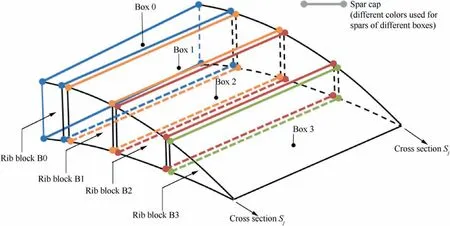
Fig. 7 Adaptive trailing edge bay, conceptual scheme.

where BMfis the amount of BMU supposed to be absorbed by the generic front spar cap;hfthe height of the front spar;BMrthe amount of BMU supposed to be absorbed by the generic rear spar cap; hrthe height of the rear spar.
Normal stress induced by bending moments at front and rear spar caps were imposed equal to σref=0.7σtu, i.e. to the 70% of the ultimate tensile stress of the specified material.
Such a further safety factor was considered to reduce undesired effects correlated to simplifications made for preliminary sizing purposes.
Required areas for front and rear spar were then obtained as

5.2. Spar webs, skin panels, rib plates thickness
The x-position of the ultimate shear force at the generic section was obtained as

where TMUis the ultimate torque moment at the referred section, and SUis the ultimate shear at that section.
Shear centre x-position was assumed equal to

where Xfand Xrare the positions of the front and rear spar webs,respectively.Standing the assumptions,the effective ultimate torque moment was approximated by a dummy value,which was given by

The shear flow qiwithin a cell enclosed by an area Ω was obtained by means of the Bredt formula:

Finally,the shear flows q within the generic section element were evaluated as
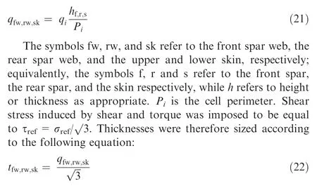
The thickness of the rib plate was assumed to be equal to the maximum value between the forward and rear web plates thickness.
6. Aeroelastic design
Such a classical sizing procedure should have been checked against aeroelastic issues. In fact, morphing structures introduce further degrees of freedom, so that a more intense coupling with the airflow is expected leading in turn to a more complex dynamic behaviour.56Adequacy of stiffness and inertial distributions were then verified versus potential flutter occurrence in the design envelope. Sensitivity studies involved simplified but reliable structural and aerodynamic models,particularly referring to the effects induced by variations of the actuator chain stiffness in combination with other intrinsic properties of the ATED structure. Analyses allowed identifying a bundle of instability-free system layouts,to tune the preliminary outline properly.57,58
The first step was devoted to realizing a stick-equivalent representation of the complete wing.In fact,aeroelastic studies shall be referred to the complete system and not to a part of it.Of course,this also means that whenever some additional morphing elements should be taken into account,iterative analyses would be performed in order to arrive to a complete assessment. Stiffness and inertial properties were extracted from two FE models with different levels of complexity, elaborated within SARISTU and referring respectively to:
(1) Right wing box structure.
(2) Right wing structure, including conventional leading and trailing edges architectures.
Wing and winglet elastic axis positions were determined through two separated and equal iterative processes, articulated into eight steps:
(1) Definition of a trial position for the elastic axis.
(2) Addition of nodes at the intersections between defined axis and rib planes.
(3) Generation of rigid elements to connect each rib boundary to the respective intersection nodes.
(4) Application of an arbitrary torque MTat the wing tip,in correspondence of the local intersection node.
(5) Evaluation of the consequent displacements through a classical static analysis,including:Tzi—vertical displacement of the intersection node at the ith rib (bending);Ryi—rotation of the intersection node at the ith rib around the elastic axis (torsion).
(6) Ratios λi=|Tzi/Ryi| evaluation, representative of the actual shear centre offset with respect to its trial position.
(7) Chordwise shift of the intersection nodes by λi.
(8) Repetition of Steps (4)–(7) till convergence: assessment of the stick model line.
Wing and winglet boxes spanwise stiffness distributions to be deployed along the equivalent beam were determined by the classical equations which were referred to a Cartesian reference system xyz,with the origin at the boxes root,y oriented along the elastic line, and the xy plane coincident with the boxes middle surface:
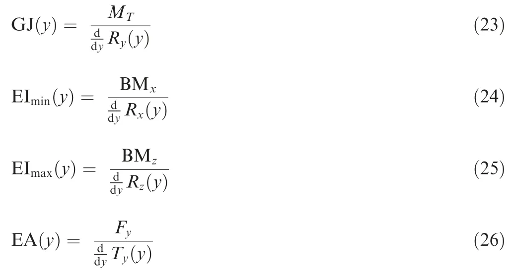
In the above equations, GJ(y), EImin(y), EImax(y), and EA(y) are the torsional, vertical bending (up and down), lateral bending (fore and aft), and the normal stiffness distributions.Analogously, BMx, BMyand Fyare vertical and lateral bending, and normal force, in the order, while Rx(y), Rz(y) and Ty(y) are the corresponding rotations, and translation functions along the elastic line y.
The stick model representing the morphing trailing edge was based on a unique hinge line located at the 85% and 88% of the wing chord for the inner and the outer wing regions, respectively. Related stiffness properties were obtained once more by the above equations.Rigidity contributions of all the other structural items (for instance, fixed leading edge, non-movable parts of the trailing edge, and so on)were deemed negligible.
Instead, mass of all the system parts was taken into account. For the generic item, inertial properties were extracted from finite element models, and simulated via lumped masses at the representative nodes. A proper offset considered the distance between the centres of mass and the elastic line.Left wing structural model was obtained by mirroring. The two segments were then connected through a mathematical synthesis of the wing-fuselage interface stiffness. The same approach was followed for linking wing and winglet elastic axes. Morphing trailing edge hinge lines were linked to the wing elastic axes via rigid elements, still preserving adaptive system rotation capability. Actuators stiffness was finally simulated through torsional spring elements,then eliminating free motions. A representation of the final condensed model is reported in Fig. 8.57
Doublet lattice method was used to compute unsteady aerodynamic influence coefficients matrices. The lattice was made of eight macro-panels deployed along the middle wing plane, further meshed into elementary boxes, whose density was conveniently set for the different parts of the structure;in particular, it was denser at the morphing components, as shown in Fig. 9.57Liner spline functions were used to derive modal displacements applied at the aerodynamic boxes centre and attached to structural model nodes.
Having completed the combined aero-structural model, as shown in Fig. 9, a parametric flutter analysis was carried out by using the PK-continuation method with generalized aerodynamic forces rationalization for evaluating coupled eigenvalue trends versus flight velocity up to about 300 m/s(1.5 times the dive speed value).
ATED inertial and stiffness distributions,and elastic deflection frequency at locked actuators (even called harmonic or morphing frequency)were the reference variables,up to a total of 45 configurations,as better described in Table 4.In order to get the desired frequency,f,the actuator torsional stiffness was imposed equal to I(f/2π)2, with I being the adaptive trailing edge inertia around the hinge line.
The study allowed determining flutter speeds and principal structural modes involved in each detected instability. Bellshaped and sharped flutter-types were detected, and both occurred in all cases but at different speeds.
The first type was mainly due to the coupling of the first symmetric wing bending and the outer trailing edge symmetric harmonic at 0 Hz.
The second type was instead correlated to the action of the first symmetric wing bending,the outer trailing edge symmetric harmonic and outer wing symmetric torsion.
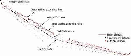
Fig. 8 Dynamic model of wing equipped with ATED.57
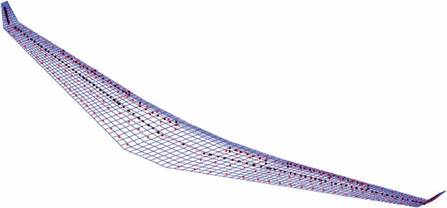
Fig. 9 Aeroelastic model of wing equipped with ATED.57

Table 4 ATED parameters for trade-off aeroelastic analysis.
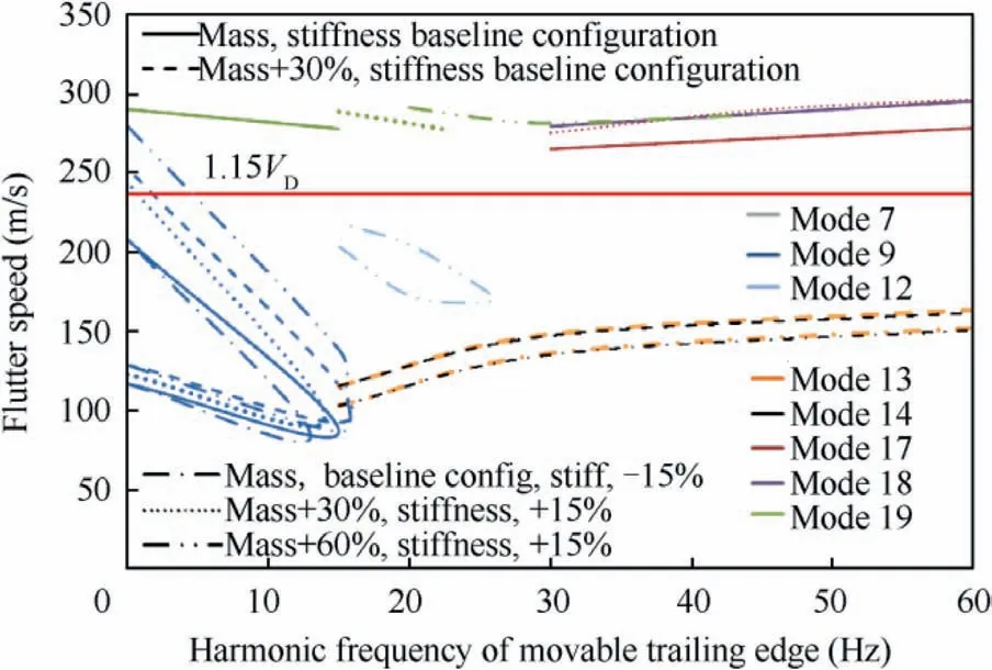
Fig. 10 Trade-off flutter analysis, carpet plot of critical cases.58
To efficiently highlight the critical combinations of tradeoff parameters,critical speeds related to the same flutter mechanism(/flutter mode)were plotted versus the ATED harmonic frequency into a unique carpet plot, as shown in Fig. 10. The red horizontal line in Fig. 10 at 1.15 dive speed divides the graph between the safe and unsafe domain for flutter speed according to CS-25, paragraph 629. As ATED stiffness is reduced by 15% while its inertia is kept equal to its nominal value, flutter occurs at speeds lower than 1.15 dive speed irrespective of the ATED harmonic frequency.A similar result follows if inertia is increased by 30% and stiffness is maintained at its reference. Those dangerous combinations were then avoided. For all the other configurations, harmonic frequencies over 30 Hz resulted sufficient to avoid any flutter instability in the target region,becoming a mandatory requirement for the actuation system designers. In case of actuators failure(harmonic frequency equal to zero),flutter was found to occur always at speeds within the certification envelope. In such a case, flutter could be avoided by the introduction of suitable balancing masses.
7. Executive structural layout
ATED functionality should have been proven by experimental tests carried out on a 5.5 m span full-scale technology demonstrator, representative of the reference wing tip and equipped with all morphing devices and related systems conceived and realized within SARISTU.59
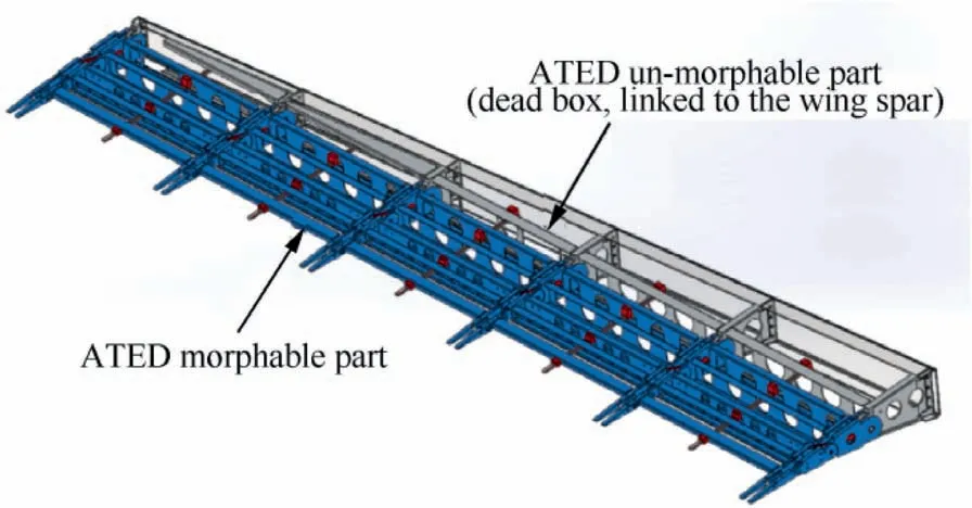
Fig. 11 ATED demonstrator layout (wing tip region).
Rooms available at the wing tip,definitely more demanding in terms of design and manufacturing, because of the taper,required a rational extrapolation of the assessed outline to that region. Executive drawings were derived from design and implemented industrial experience. They were mainly oriented to increase system robustness, reduce production costs and abridge assembly and maintenance processes. ATED overall appearance is reported in Fig. 11. The primary structure is made of four boxes composed of five bays: the inner box in chordwise direction (dead box) is fixed and rigidly connected to the wing box through an interface spar; the others are driven by active ribs, each commanded by a couple of actuators linked to the block B2. Kinematic chain is devoted to bear occurring loads as it is fixed in a certain configuration.
The active rib architecture was chosen to have duplicated blocks while links were located inside them, as shown in Fig. 12. Such a compact and robust solution prevented interferences between links and other structural parts. Kinematic hinges were implemented through frictionless bushings and bearings.Where necessary,spherical hinges were used to compensate bending displacements that could provoke mechanism jamming. Commercial off-the-shelf components compliant with aeronautical standards were always referred to. System interferences were verified up to twice max nominal excursions to enable motors to recover elastic deformations of the driving chain,thus permitting to restore target morphed shapes under load. Active rib was also shaped to host the morphing skin,and the sensing system.Block B1 outline did take into account the possibility of integrating proper mass-balances for flutter clearance even in the case of complete actuator system failure.Spar and stringers sketches were adapted to morphing kinematics and skin design, while ensuring established stiffness.A focus was placed on spar webs cut-out at actuation leverage,in order to avoid interferences during motion.
8. Skin
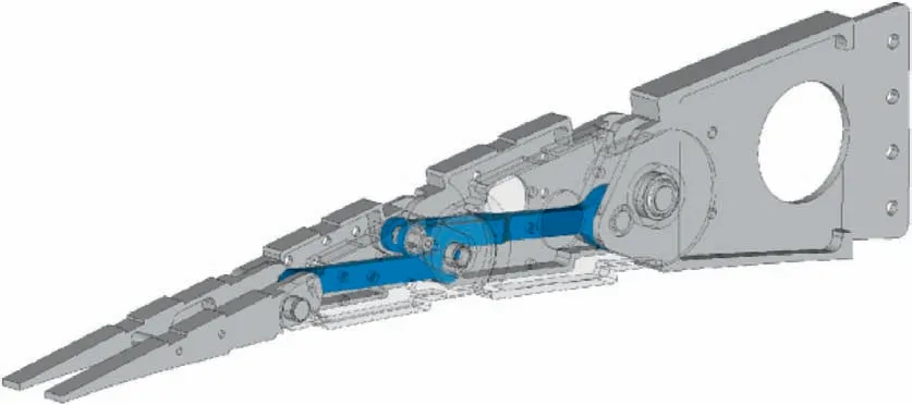
Fig. 12 ATED, morphing rib layout.
Morphing skins represent perhaps the more challenging aspect of the adaptive structures, and by now, no assessed solutions are reported.To preserve geometry continuity,pure kinematic solutions are not viable, bringing in themselves the need for gaps and broken lines. The reference problem is the same as for all other items:to attain a system that is able to both strain and bear forces whether internal or external.In this case however prospected solutions are complicated by the necessity to have a continuous system that shall deform longitudinally and be practically rigid transversally. Maybe it is interesting to note that in the reported case, axial action is performed by interior mechanical forces (in this case, resistance should be reduced to a minimum), while normal excitation is coming from the aerodynamics (in this case, stiffness should be brought to a maximum). Another relevant issue is related to the necessity of creating a continuous system along both the main curvilinear directions of the wing surface, i.e. chordwise and spanwise, because any interruption would be inconsistent with the initial assumption of aiming at a continuous surface.The first problem may condition the production process significantly.
In SARISTU, many investigations were performed by the Fraunhofer Institute IFAM(Institut Fu¨r Angewandte Materialforschung),all including both rigid and soft materials.60–62A representation of the proposed layout is reported in Fig.13.In synthesis, it consisted of soft foam lines, with variable thickness to take into account different spaces available and diverse loads acting chordwise, metal plates meant to house and support those elements and,above all,to ensure a proper connection to the structural skeleton,and a thin cover elastic layer to guarantee smooth continuity. In detail, the soft parts were deployed at the hinges positions,so as to absorb driven deformation, while aluminium panels were located in correspondence of the movable blocks and were devoted to a structural function. The external coating had only a geometrical purpose.
Such a kind of arrangement did assume that the deformable parts would have been able to resist high strain, much larger than the mean one, fixed at 2.5%. In fact, their localization implied in turn that the overall stretch should have been absorbed there.Easy computations predicted a 5%value,very demanding above all with respect to fatigue aspects. Metallic segments were not aimed at bearing strains, while external coating did undergo uniform deformation. Therefore, shear was expected to arise among the components,in turn affecting fatigue behaviour.Since fatigue is critical for elastomers,it did follow that one of the main issues of such classes of solution regarded the temporal behaviour (including aging). These properties were required along all the typical range of working of commercial aircraft, i.e. between -55 and 80°C, in combination with chemical resistance to standard substances, commonly employed (for instance, skydrol). The choice to confine the strain in a small region was mainly due to structural instability issues, namely buckling, because it was necessary to take into account tension and compression.
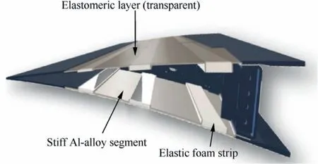
Fig. 13 ATED, morphing skin layout.
In order to be conservative with basic requirements, material was designed to resist to around 10% max strain for one thousand cycles, respectively twice and five times the nominal specs. It should be in fact reminded that the developed device should have been performed one half cycle per flight, for instance from max downward to max upward extension, with no return. Specific attention was paid to the bonding among the three components, indispensable for adequate load transmission.
Elastomers are commonly used on aircraft and adequately certified like EPDM rubber;the most of them are used like sealants, but are not suitable for structural-like applications. The main reason is that elastic modulus is not stable at low temperatures where glass transition takes place. In the variety of silicone materials there are some that exhibit stable properties in the targeted environmental range,even though characterised by the common drawback to be hardly glued. At the time of the SARISTU project,there were no commercial products able to match all the established specs.Therefore,IFAM selected a process involving reactive platinum-catalysed low-temperature formulations, specifically tailored for the envisaged application.
Specifically,the use of fumed silica allowed increasing stress and strain resistance. Its relative concentration however affected the preparation; it was found that values higher than 15% made almost impossible the process. Furthermore, to have a certain control on the reaction, inhibitors or catalysts were implemented.
IFAM was able to obtain almost constant mechanical properties in the considered range.This was essential for guaranteeing stable reference for the actuators and control system action that would have otherwise been compensated on-line,with serious impacts on their design and stability. In the defined architecture, skin played in fact an important role in the mechanical force needs and gave essential features for the proper sizing of the overall kinematic system.Such properties were verified experimentally,with many tests performed at different temperatures in the range of interest.
Data allowed to tune a hyper-elastic model,and then implemented into FE simulations. Fatigue tests were conducted on an assembled specimen, therefore involving the used materials and the bonding, an essential element for the proposed solution. Cyclic load was applied at different frequencies in order to get statistically valid results. Failure case was established as the first crack insurgence, verified by visual inspection.
A significant difference was detected for low and high strain values:in the first case,a first crack did appear and then propagated, while in the second one no crack evolution was evident, so that total collapse should have been considered.
It should be reported that in both cases breakdown was due to fracture of the foam. Similar results were achieved for different temperatures, including standard room (25°C) and low limit temperature (-55°C).
The outcome of that extensive test campaign permitted to state that the assembly was able to resist far more than 200 thousand cycles at 10% strain, well over the targeted objectives. As extreme specifications are considered, the situationis the one reported in Table 5(linear scale;for cycles,log scale should be referred to;in that case the safety coefficient may be quantified in 1.5). In the end, it could be concluded that released skin could be classified as fail-safe during standard operation life.

Table 5 ATED skin module, fatigue behaviour.
Concerning the manufacturing process,it is worth mentioning that adequate adhesives to ensure the cohesion of the threepart morphing skin were unavailable in commerce and therefore a specific assembly process had to be drawn.It was based on carrying out foaming,curing,and bonding altogether;such a challenge increased further, for the necessity of realising a more than 2 m long single body, suitable for being installed on the ATED demonstrator.
A special 150°C heating device was then realized, to be integrated in the reference mould. Manufacture did fully succeed.
9. Actuation system
One of the main challenges of morphing structures is to maintain the capability of withstanding aerodynamic loads while exhibiting suitable deformations.63There are different ways to face and overcome this problem:the authors choose to refer to architectures implementing load-bearing actuators, able to sustain the operational forces while providing requested displacements. More specifically, the actuation of the device was driven by lever mechanisms combining structural and actuation functions. The finger-like outline proposed in the concept design allows smooth morphing transition if associated with high-flexible skins. ATED kinematic architecture ensured an interesting load reduction property in transferring only a part of the incident load to the actuator,further reduced by an appropriate gearbox, finally guaranteeing a total transmission ratio over ten. A detailed analysis of the ATED kinematics,necessary for the actuation chain synthesis,highlighted the main characteristics of the blocks movement with respect to the wing (reference body).64–66It was found that:
(1) Block 1 underwent pure rotations around the 1st hinge.
(2) Block 2 rotated around a‘‘virtual hinge”,determined by the link lines and the physical hinges layout.
(3) Block 3 exhibited combined rotational and translational motion.
These results led to the following guidelines:
(1) Actuation on Block 1 required larger load values than on other blocks.
(2) Actuation on Block 3 would have arisen serious drawbacks for the active kinematic arrangement, standing the very limited available room and the distance from possible motor installation.
(3) Actuation on Block 2 did not show specific shortcomings.
This latter solution was then preferred and was considered in the next phases of the development. Coherently with the design hypotheses,the actuation system should be proved with respect to cruise load(operation)and dive speed(the most critical condition).In those configurations,the system should have then provided sufficient motion and blocking forces, respectively,to guarantee an arbitrary shape in the defined envelope,and sufficient safety levels at limit conditions. Standing the final target of the SARISTU project to test the ATED on a 5.5 m span full-size wing section, representative of the tip region,the system design focused on that geometry.The major restrictions derived from the limited room available for the hardware integration, typical of that zone due to wing tapering. Taking into account the fixed chord of the ATED(34 cm)and the distance of the rear spar from the trailing edge tip, it came out that a section of 215 (chordwise) by 108(thickness-wise) mm2was available at the root, reducing to 80 by 72 mm2at the other extremity, as shown in Fig. 14.
The actuation system should resist both external loads,deriving from aerodynamics, and intrinsic loads, mainly of mechanical nature deriving from the need of stretching the skin. Inertial loads could instead be neglected because of the quasi-static nature of the addressed device, aimed at compensating fuel burnt during cruise and ranging from -5° to +5°.in a complete flight with the established resolution of 0.5°.Actuator loads assessment was completed by other considerations involving the non-tapered ATED chordwise extension.As an immediate consequence, percentage of wing chord covered by that device increased towards the wing tip, in turn leading to higher pressure loads;in fact,the device root moved figuratively towards the leading edge in a non-dimensional coordinate representation. Therefore, the aerodynamic forces applied to the morphing system were expected to increase towards the wing tip, further exasperating an already unfavourable condition for the abovementioned room constraints.
Mechanical opponent force arose from compliant skin stiffness.Deformable part of this component was made of an elastomeric cover (magnitude of the Young modulus around unit MPa), several mm thick and some cm long. It is perhaps the case to highlight the difference between these two kinds of resistance that the ATED should undergo: aerodynamics is always active and its presence derives from the external environment;skin resistance only arises as the device tries to move.Therefore, blocking force should have been evaluated for ensuring a certain shape only with respect to the airflow actions. Instead, as the device tries to move and kinematics is released, the actuator should have been able to replace constraint forces, overcome aerodynamic pressure variations (if opposite) and win the skin resistance.
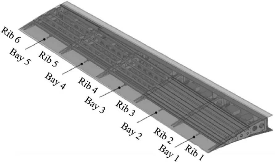
Fig. 14 ATED geometry: areas for actuators integration.
A simplified but reliable multi-body model was set up to compute realistic actuators loads within a commercial explicit solver.Actuators loads were calculated with respect to aerodynamic pressure loads and skin stiffness, simulated through concentrated spring elements.Having assumed a 2D behaviour of the system, therefore neglecting the effects of transversal forces and out-of-plane section rotations, a single bay of the SARISTU demonstrator was modelled,and classically defined as the wing section between two consequent ribs.Indeed,actuators action was aimed at providing movements in the rib plane, while crosswise kinematics should be investigated for chain jamming.
ATED blocks and links were modelled as rigid elements,while the morphing skin was represented by a number of rigid plates connected through concentrated elastic springs, representative of the polymeric segments.Action requested to actuators was computed as a concentrated moment acting on the connected block. It was found to be mainly dependent on the mechanism outline and the aerodynamic forces, while the compliant coating contributed only by a fraction. Torque was derived in this way:
(1) A tip displacement was imposed, matching a unique deflection angle (SDOF kinematics).
(2) Aerodynamic forces were imposed as derived by CFD elaborations for that configuration.
(3) Two hard springs were added to the model.
(4) Analysis was restarted; the springs elongated negligibly,then maintaining the achieved shape, but expressed the nominal force suitable to hold the ATED in the given configuration.
(5) Torque was evaluated through the product of those forces by respective arms with respect to the centre of rotation of the actuated rib.

In the assessment of the actuator kinematic, several architectures were considered with the aim of reducing the produced torque, directly affecting system weight and size. Having in mind that the load transmission point was defined at the central block, a trivial consideration descended: a normal or a parallel force to the camber line would have transmitted a moment proportional to the chord distance or the thickness value from motor location, respectively, different for magnitudes.However,because it was decided to release a completely embedded mechanism(smart system),it was necessary to select the second, trying to deviate as possible towards the first layout.
The first and second architectures were characterized by an arm rigidly connected to the actuating block(lever),moved by another arm rigidly connected to the actuator shaft (crank).The connection point between those elements sled with respect to each other, to enforce movement. The difference between the two layouts was that the position of the motor point of rotation was inside or outside the lever length region.The third architecture was a bit more complicated and used a linear rather than a rotational actuator. Its translation was transformed into a rotation by a further lever,connected to a pivot that rotated and transferred the motion to the block,from this point ahead, in the same way as the other configurations. A sketch of the different layouts is reported in Fig. 15. Labels are reported exclusively with reference to the first architecture.
With reference to the above notations, some expressions could be defined to describe the kinematic characteristics of the system proposed along the first outline.Mechanical advantage was defined as the ratio between kinematic and driving moment: the higher that value, the better the expected performance.
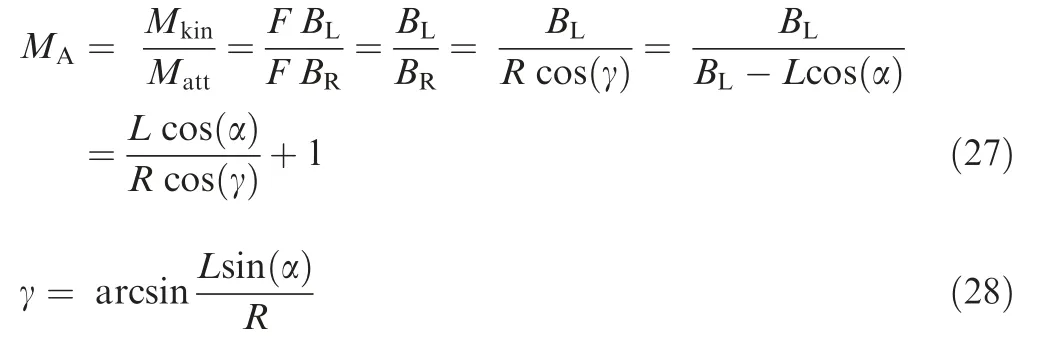
For small angles α, the above formulas could be simplified as the following expression (similar formulas may be obtained for the other sketches, herein not reported for the sake of brevity):

Related results are shown in Fig. 16,where MAis reported for a reference configuration with L=7 and R=1. Both exact and approximated functions are shown.
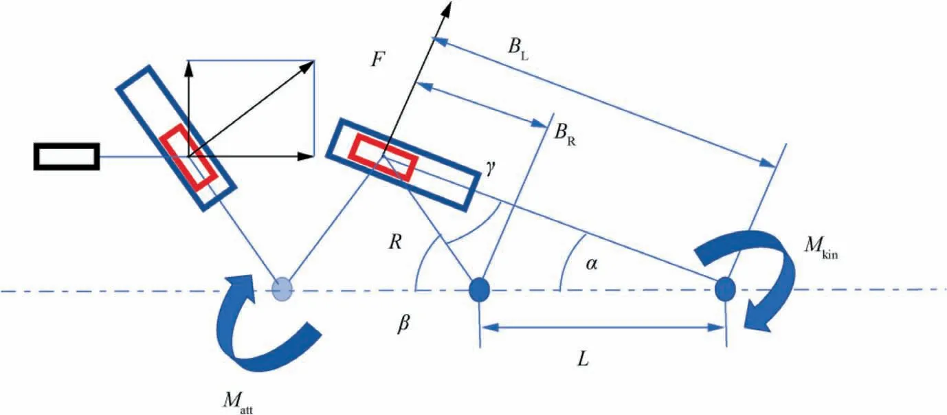
Fig. 15 ATED actuation layouts (labels are reported exclusively for the first architecture).
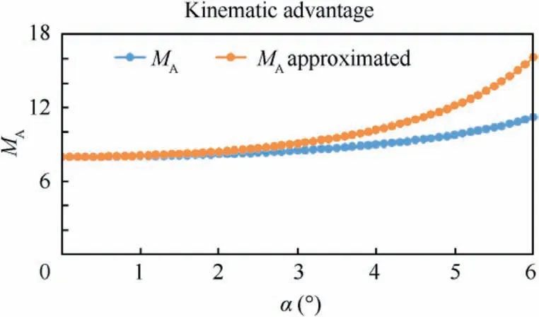
Fig. 16 ATED: kinematic advantage of actuation system.
Such a configuration was selected for the higher MA values,the most compact layout, and the minimal complexity with respect to the others. At this point, it was possible to proceed with the selection of the most suitable actuator, available on the market. In fact, one of the main targets of the project was to arrive to systems that could be actually feasible and suitable for industrial production. Therefore, large attention was posed on the accessibility of the different components,trying to focus the innovation on the final product. Along the same motivations as the structural design process, the attention was focused on the constraints arisen from the demonstrator configuration, being tighter and more demanding than for the target section of the complete wing. Nevertheless, it was ensured that the attainments could have been exported towards the real setup; this step was not a standard ‘‘scalability” issue, because of the full-scale characteristics and real aspect of the envisaged prototype; however, different dimensions should have been properly taken into account. Standing the above considerations, main actuator requirements concerned with:
(1) Available torque defined around 6 N·m for operation load issues and 15 N·m for locking needs.
(2) Max volume, confined under 100×50×200 mm3,having considered the available room.
(3) Weight, arbitrarily defined under 1 kg, consistent with the overall mass estimation.
(4) Power consumption, defined under 100 W for minimum impact on the aircraft needs.
While this last parameter could drastically change with the advent of all-electric concepts, the others can be considered good reference for further evolutions of the proposed outline.Other parameters, like nominal operation voltage, actuator speed and similar, should have been compatible with aircraft standards: in that case, there were no margins of negotiation.A couple of dozen of actuators were screened among the aeronautic-certified products. Among all, four motors produced by four specialized industries (Bental, Moog, MTC,and Pegasus) outstood for produced moment over size and weight, while keeping related parameters within the specs. A simple selection was performed by referring to a merit figure as the product of volume and mass power density. Bental RSA-06 model was finally identified for its extreme compactness (less than 0.2 litres) and lightness (less than 0.5 kg).
The selected architecture imposed that the kinematic chain should have been able to bear external loads; therefore, its structural parts and the actuator itself should have been sized with this aim. The selected configuration, as shown in Fig.17,was made of a couple of motors, cranks and levers connected to block(B2)of each morphing rib,except for the demonstrator root and tip sections.The system outline started by considering the actuator placed at the largest distance from the morphing structure, i.e. attached to the rear spar, in order to dispose of the widest room and lengths to design the mechanism. The stress that the latter part underwent can be computed as the ratio between the applied moment and the flexural stiffness, Mkin/Ilever. In a reverse design, imposed the used material, that simple relation is useful to determine the beam section under the most critical load condition (Vdive).Both steel and aluminium were found to lead to acceptable results. The size of the crank was fixed in order to attain the max MA,the need to fit the assigned room within the rib,taking into account the opportunity to exploit all the rotation range of the selected actuator (±45°). From the structural point of view,the process was the same as before.Interconnection elements(pins)were verified at shear loads,confirming the possibility to implement both aluminium and steel,also in that case.
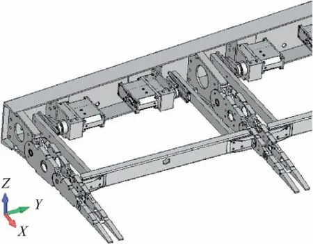
Fig. 17 Actuation system elements of ATED.
An important element of the system was the linear guide,the element that connected crank and lever, as shown in Fig. 18. DryLin linear bearings were chosen, commercial carriage lubrication-free devices, non-depending on run length and therefore non-constrained by specific stroke needs. Their main attractive features may be summarized as follows:
(1) Limited height (around 10 mm).
(2) Lightweight (around 100 g/m).
(3) Several installation options, including pre-stressed ones.
(4) Auto-lubricating.
(5) Corrosion-resistant and adequate for aeronautical applications.
(6) Good aging behaviour.
Main disadvantages of this kind of configuration are associated to the possibility of jamming by non-perfect carriage sliding (rotation); such a risk was specifically investigated in devoted experiments.
Actuator system concept was tested in lab to verify its capabilities and electronic interfaces for driving purposes. Test rig consisted of a 1 m long straight beam with a rectangular section, pivoted at a fixed hinge at its middle, and equipped with a linear guide driven by the selected motor. The following experiments were performed:
(1) Power and no power actuator passive stiffness measurement, by loading beam with a certain weight until a remarkable displacement was obtained. In detail, the system was forced until it started to move. Motor was steady until a certain moment (about 1 N·m), after which rotations arose with a defined ratio torque over angle (rotary rigidity). That behaviour held until a critical value of the external force was reached, causing almost free rotations. Power-on configuration was not characterized by a linear but a simple monotone function, with reducing slope till an almost constant value.In this latter case, a measure of the absorbed power was also carried out (between 1 and 10 W for the operational range). Measured power and no-power stiffness differed for about one magnitude (several tenth to several units of N·m/(°).
(2) Main system characteristics measurement,by applying a step signal and recording related response to derive damping, rising time and bandwidth, resulting in less than 0.1 s, around 1% and tens of rad/s, respectively.
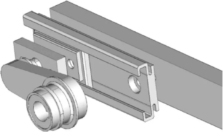
Fig. 18 Linear guide of ATED actuation system.
(3) Preliminary stress analysis was performed on a detailed finite element model.53Actuator lever was connected to the structural system at the B2 spar; a further node was added to take into account the virtual point of rotation,in turn connected to the aforementioned pieces by rigid bars. That choice di lead to unrealistic values of the stress field in the region of the spar attachment that were then not taken into account.The remaining parts of the adaptive wing were not modelled. The main box was substituted by a perfect clamp, increasing therefore the load over the areas of interest (conservative procedure),while segments toward the free tip did not contribute to the overall stress levels in the investigated domain. A consolidated approach did suggest to simulate the overall system by means of solid elements,whose typical size was units of mm.The full model consisted of more than 130,000 elements (solid, shell, and few beam) and around 180,000 nodes. At loads corresponding to Vdiveconditions, overall displacement field was limited to around 5 mm. Stresses and strains resulted well below the yield limits of the used materials(whether aluminium or steel,depending on the part).Attachment region estimations were not considered reliable because of the necessary discontinuities and mesh irregularities; there,classical engineering procedures were instead implemented (bolts, rivets, and so on). Higher stress values were detected towards the wing tip, due to the higher dynamic loads with respect to the available material quantity.
An adaptive control system was specifically designed to guide the individual rotary actuators with the aim of forcing the structure to achieve the desired shapes capable to enhance aircraft performance. The Bental RSA-06 electromechanical actuators were driven by PWM signals whereas the actual trailing edge shape was monitored through a both chordwise and spanwise FBG-based sensor system. At each iteration,the control logic analysed the ATED shape data by comparing the actual shape with a given set of desired wing shapes,stored in a database, ensuring improved values of aerodynamic efficiency in cruise.The process concluded when such a difference was lower than a threshold value,broadly representative of the shape measurement accuracy.
10. Sensor system
Adaptive structures are always associated to large strains and motions,whether they are kinematic,compliant,deployable or inflatable. Because of those characteristics, resulting architectures are very complex and made of many components assembled together; monitoring of interfaces (including mechanical and bonding connections) has therefore a certain importance.It can be stated that availability of extended sensor networks is a key technology enabler of morphing structures; however,standard sensors may face several showstoppers in their actual implementation like limited strains, integrability, cabling, and so on. Many alternatives are emerging at the level of both architecture (for instance, multiplexed, distributed or quasidistributed,wireless,very-thin),and device types(for instance,sprayable, optic). In the herein reported case,67–70multiplexed optic systems were referred to, and specifically Fibre Bragg Gratings (FBG), a local discontinuity of the fibre refractive index that can be created through different techniques,including lithography. Technobis, Inasco, and Cira carried out this activity, mainly.
Depending on the application and the available electronics(superstructure,chirped,tilted,and so on),such elements may be selected with different characteristics; for the investigated morphing system, uniform FBG were used, as shown in Fig. 19, consisting of periodical irregularities.71Those engravings may easily work as sensors:as light goes through the optical fibre and meets the grating,it is partially reflected in a band centred at a certain specific (Bragg) wavelength, λB, in turn corresponding to a determined frequency. Wavelength used in typical telecommunication silica fibres ranges between 1310 nm and 1550 nm. Examples of involved variables magnitude are given in Table 6.
Since realized anomalies are influenced by physical layout,refraction is subject to thermal, mechanical, and thermomechanical strains. If a stress field loads the fibre, its elongation(or contraction) induces a variation of the periodicity of the incision, in turn providing a frequency shift of the absorption peak that gives an indirect measure of the occurred transformation. The physical relation governing this displacement is linear and systems devoted to its detection are commonly known as interrogators.If the input spectrum is large enough,many sensible elements may be deployed on a single line(multiplexing); in that case, the challenge is to individuate peaks motion separately, whether in statics or in dynamics. Current technology gives access to a number of such instruments,based on very different principles (basically spectrometry and interferometry), and that can be classified per cost, reliability,weight, etc. For very demanding aerospace requirements, special approaches are used;72inside SARISTU, Demynsis was selected, a four-channel interrogator able to read 32 different sensors at 20 kHz, working on integrated photonics technology, and particularly suitable for damage and impact detection, load monitoring, and shape sensing, while including redundancy aspects and time division features.
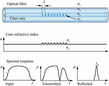
Fig. 19 Working principle of FBG.71
Aerospace environment needs high-performance connectors in terms of reliability, operation, and maintenance, in order to ensure satisfactory optic,environment, and mechanic behaviour. Usually, Physical Contact (PC) and Expanded Beam (EB) connectors are used. The first ones give very good optical features, with easy and robust alignment characteristics. The second type guarantees reduced signal loss through dedicated interfaces contamination and, because of an intermediate gap between the connecting parts,mechanical interference wear is virtually eliminated. In SARISTU, PC-type connectors were selected, preferring robustness as driving capability.
Specifically, an FBG-based sensor network was designed for reconstructing ATED shape, and enabling feedback control. It consisted of two different basic components: being the expected strains very different along the two directions, it was useful to split the problem concerning spanwise and chordwise systems.In the first case,typical structural deformation values were expected, in the range of several thousand microstrains; therefore, in this case, the device was made of a simple ribbon tape protecting an optical fibre with a single grating per bay. The things were different chordwise, where expected strains should attain values around 2.5%. Because there are no commercial or cheap fibre sensor systems capable of bearing those figures, a special mechanical modulator was ideated and built. It consisted of a simple cantilever beam, as shown in Fig.20,close to neutral axis so as to reduce deformations at a minimum,and hold by special supports to guarantee constant distance from the skin and allow only sliding movements. In such a contactless sensing system, fibre was hosted within a channel for enhanced protection.In the end,a sensor network made of closed rectangles was realized, integrating chordwise and spanwise lines and suitable for shape reconstruction.
As stated in the previous paragraphs,since smooth and regular deformations may be predictable along the span, it was clear that the shape reconstruction problem should have focused on chordwise analysis, using other available data forcoherence estimations. Because sensor points were not located over the skin, a vector relation between detection and motion was firstly defined. Full details about the treatment herein reported, are presented in Ref. 70 Assuming that a generic point surface position was given by a couple xsi,ysiat a vector distance d=nid,where niis the skin normal at the point xsi,ysiand d the distance from the point xbi,ybi,on the beam,the following relation held with respect to a generic origin O(0,0):

Table 6 Typical wavelength of telecommunication silica fibres.
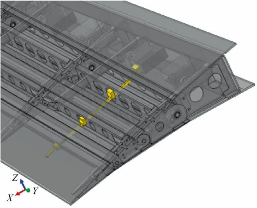
Fig. 20 FBG-based sensor system for reconstructing chordwise ATED shape.

The forces that deflected the beam in the way it was forced to move (clamped on one side and sliding at certain points)were determined by an iteration procedure,consisting in a trial and error process.Possible values were assumed for the forces and then their reliability was checked. Having sized a slender beam, i.e. thin thickness, significant length, and small width,classical reference equations for pure bending could be considered:
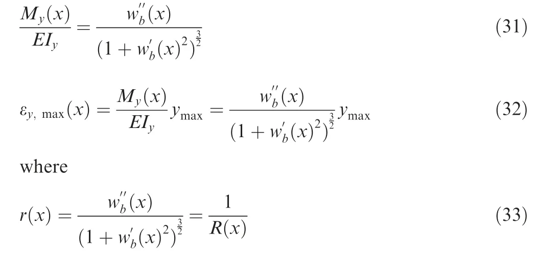
is the local curvature or the inverse of the curvature radius.For distributed terms:

In the above expressions,classical symbology was used.So,E is the Young modulus, Iythe inertia moment of the beam coherent with the investigated bending(around the beam rectangular section basis), w the displacement associated to that bending and the simple apex the relative derivative order with respect to the beam axis x.My(x)is the bending moment at the generic station x, given by the sum of the concentrated forces before or after that station(elementary forces if forces per elementary area or length had been considered).Strain in x direction,ε,was assumed linear along the thickness,so that its max absolute value was achieved at the top or bottom surfaces.If Fiwere set,general solutions would result by iterating the expressions above. Among the infinite groups satisfying those equations, the ones were chosen better approaching the condition to pass through the sliding guides or,equivalently,better keeping a fixed distance from the skin.

Moment and strain were assumed constant along the ith segment between two consecutive points.For simple cantilever beams,the free end is always characterized by zero-strain.This value held within the region between the last force application point and the tip, so that 2 more information could be assumed. By knowing curvature (or strain), it was possible to approximate the deformed beam shape by using the Frenet-Serret formulas, simplified because torsion was set to zero for loads acting in the beam symmetry plane. In such a case,those cited expressions could be written as

where r(s) is the curvature along the curvilinear abscissa s,while T, N and B are respectively the tangent, normal and binormal (cross-product between T and N) vectors at s.Because

geometry of the curve could be then approximated by iteration. Having fixed the vector position of a beam reference point with respect to a coordinate system p(0), the deformed line was finally given by

For the ATED, three FBG sensors FBG were deployed.The shape reconstruction process took advantage of the above formulas and the hypothesis that the deformed line was parabolic. Lab tests confirmed that the illustrated method permitted to determine the actual geometry with an estimated error of less than 0.5%, defined as the max relative deviation between actual(a)and estimated(x)vertical displacements,w:


Fig. 21 ATED shape detection by FBG sensors.70
An example of the attained results is reported in Fig.21,70where camber time evolution is shown, after repeated activation of the adaptive structure.
11. Conclusions
As any other device, when addressing a morphing structure,the main question that shall be answered is what is the aim and what extent that enclosed system may contribute to. The answer is never trivial, above all when few investigations are available in literature, or there are none at all. In the case of the ATED, the genesis of the related concept came from the aerodynamic consideration that camber variations during cruise could compensate lift excursions due to weight decrease for fuel burning, and the architectural understanding that an easy way to realize it was to enable adaptations of the trailing edge,one of the least loaded parts of the aircraft wing.The second step was to choose a suitable aircraft where that concept could be applied: a medium-size commercial aircraft, 7-hour mean-route, was then selected.
On those bases,a pre-design activity was carried out to individuate the optimal geometrical size of the system that would have in turn determined its gross impact on the added complexity and costs. Preliminary aerodynamic investigations allowed to size the adaptive trailing edge extension to 10% of the MAC and about 60% of the wing span, i.e. coincident with the flap region(outer wing).Target deflection range was instead fixed at ±5°. In order to give a base of reasonableness to the study, a very first estimation of the expected performance was drafted, using as a reference not only a non-deformable wing but also a simpler device made of a plain flap.This last test gave an outstanding sensibility about the benefits achievable by morphing versus classical consolidated systems (much simpler,cheaper and safer). The synthetic numbers that resumed the key answers to the aforementioned questions can be herein reported as 5%fuel savings over a classical mission,and twice(2×)the benefit produced by a single tab architecture.
Once the reference environment was established,the concept was formulated and presented,consisting of a complex architecture made of four components,usual of any controlled morphing system:a structural skeleton,an actuation network,a sensor grid,and an enveloping skin to guarantee geometrical continuity. Regarding the control system, its description is moved to next works describing ATED evolution and arrangement,being the whole topic too large to be fitted within a single work.
The structural skeleton posed different challenges that should have been faced. The major ones were the capability to withstand external loads while deforming, and the possibility to implement Single-Degree-of-Freedom (SDOF) mechanisms to synthesize camber variation as a unique control variable. ‘‘Active ribs” were introduced to substitute the original ones, made of three movable segments plus a fixed one ensuring the connection to the rest of the aircraft.The four different blocks were hinged in alternate pairs by stiff mechanical links. Longitudinal spars did ensure proper torsional resistance. The resulting architecture was a true SDOF system,whose residual mobility was driven by the actuator network.Because the motor targeted the suppression of the free kinematics, it had to have ‘‘load-bearing” characteristics, in the same way of what happens for standard wing movables (flap,ailerons, and so on). In this manner, it was really difficult to separate actuator and structural systems, or even think of the structural design without considering the presence of the stiffness and robustness of the mechanical actuating equipment.This simple concept paved the way to a design evolution where those two elements are considered together, since the very early stages.
On such points, some considerations arise. Nominally, the entire architecture had just one degree of freedom,i.e.the ribs moved synchronously.This was also ensured by the longitudinal spars that absorbed rotation loads, or equivalently,avoided twist. However, the structure was elastic; so, if it is true that spanwise angular movements were somehow confined,it is also true that they could still take place to a certain extent. In the referred configuration, it was found that each bay could rotate up to 0.5°. with respect to the adjacent ones.Indeed,that was a small value,but sufficient to generate up to 3°. twist along the whole span of the 5-bay demonstrator(asynchronous way of working). Along with this consideration, it should be added that, if desired or specified, the introduction of additional degrees of freedom like twist, should be considered at the beginning and not expected to reveal at the end of the design process.
Segmented kinematic systems display concentrated discontinuities that can somehow hamper the attained or envisaged benefits.In order to avoid that,a suitable multi-material morphing skin was imagined and realized, compliant to the issued specs. In the developed configuration, its main features were:sustaining strains up to 5%(concentrated at the blocks hinge),exhibiting stable characteristics in the range between -50 and+80°C,withstanding over 20,000 cycles(corresponding to the classical number of flights after which a general inspection of the aircraft takes place). Because geometrical continuity should have been preserved spanwise, further than chordwise direction, the manufacture was established as a single-shot process for releasing a regular, uninterrupted sample.
Finally, sensor system had the ultimate duty to detect the actual shape of the morphing device under concurrent internal and external loads,which produced deformations that could in turn generate forms even far from the prescribed ones. That capability was essential in a feedback control architecture.Because distortions from the target configuration should have been retrieved, strain sensors did have the most obvious choice. In order to recover shape information, a suitable network was built, made of chordwise and spanwise elements.While latter deformation values were expected to fall within usual domains for standard sensors (thousand microstrains magnitude, or 0.1%), the former ones were awaited to attain percentage units, up to 5%. Then, an original sensor system was developed, tested and implemented, capable to modulate strain to usual values and to allow implementing commercial gauges (smart beams). Collected data finally permitted to reconstruct the morphing shape under operational loads.
Some final words shall be devoted to the overall system,with specific mentions to the structural part.In the paper,special sections were dedicated to aeroelasticity and manufacturing issues, although brief. The first one was associated to the declared increase of structure mobility, necessary to achieve specified morphing figures. This necessity did in turn complicate the dynamic response of the analysed system, and therefore its aeroelastic behaviour, which should have been checked to avoid the insurgence of undesired instabilities(flutter, above all). That investigation segment opened the way to many other researches, still ongoing at this time, anticipating the need of modifying the current paradigm of the aeroelastic approach. Instead of verifying the effects ‘‘after” the first design loop, the authors and many colleagues of theirs, are currently investigating methods to include coupled aerodynamic and structural issues at the beginning of the project.
Concerning handcraft construction, one of the paramount difficulties was the multiplication of the number of parts,and at such levels they did directly affect costs,safety and reliability.In morphing systems,such an aspect is almost implicit.A way to solve that concern is to drastically change the approach towards compliant ones; another possibility relies on the use of Additive Layer Manufacturing(ALM)technologies. In that latter case, it could be viable to think to complex structural systems that,moving from CAD to FEA for validation, enter directly SW tools for driving ALM realizations,which in turn could directly deliver final products in future evolutions. This may be not a special demand for standard structures but could be an enabling capability for morphing structural systems.
Declaration of Competing Interest
The authors declare that they have no known competing financial interests or personal relationships that could have appeared to influence the work reported in this paper.
Acknowledgment
The research herein reported did gratefully receive funding from Seventh Framework Programme of the European Union(FP7/2007-2013) under Grant Agreement N.284562, SARISTU. The project was prodigiously and effectively coordinated by Piet Christof Woelcken (Airbus) with the support of Michael Papadopoulos (EASN – European Aeronautic Science Network).
The authors want to thank warmly and individually the colleagues who remarkably performed the different investigations above reported,and those widely referenced in bibliography,as follows:Katrin Genzel,Ben Newman,Piet Christof Woelcken(Airbus); Salvatore Ameduri, Monica Ciminello, Gianluca Diodati (Cira); Andre` Gratias, Mathias Lipowski, Martin Schueller (FhG-Enas); Andreas Luehring, Christof Nagel,Bernd Schneider, Oliver Schorsch, Michael Wolf (FhG-Ifam);Shlomo Rosental, Moshe Steinbuck, Avner Volovick, Lior Zivan (Iai); Christos Koimtzoglou (Inasco); Giovanni Marco Carossa,Giuliano Cattaneo,Domenico Cavezza,Carlo Ricciardelli,Salvatore Russo,Lorenzo Rossi(Leonardo);Marco Bellucci, Alfonso Celano (Mare); Antoine Dumont, Jean-Luc Godard, Fabien Huvelin, Cedric Liauzun (Onera); Sergio Ricci, Alessandro De Gaspari (Polimi); Rolf Evenblij, Merlijn Kuin, Iskander Deerenberg (Technobis); Francesco Amoroso,Leonardo Lecce,Marco Magnifico (UniNA).
In memory
The authors dedicate with gratitude this work to their friend and colleague Alfonso Apicella (Leonardo), one of the very first originators of SARISTU concepts and themes.
 CHINESE JOURNAL OF AERONAUTICS2021年7期
- CHINESE JOURNAL OF AERONAUTICS的其它文章
- Integrated batteries layout and structural topology optimization for a solar-powered drone
- Polynomial networks based adaptive attitude tracking control for NSVs with input constraints and stochastic noises
- Morphing wing flaps for large civil aircraft:Evolution of a smart technology across the Clean Sky program
- Review on bio-inspired flight systems and bionic aerodynamics
- Continuous morphing trailing-edge wing concept based on multi-stable nanomaterial
- A hybrid multidimensional Riemann solver to couple self-similar method with MULTV method for complex flows
