Continuous morphing trailing-edge wing concept based on multi-stable nanomaterial
Fengqin HAO, To TANG, Yun GAO, Yimeng LI, Shenghui YI,Jin LU,,*
a Department of Mechanical Engineering, City University of Hong Kong, Hong Kong 999077, China
b Centre for Advanced Structural Materials, City University of Hong Kong Shenzhen Research Institute, Greater Bay Joint Division, Shenyang National Laboratory for Materials Science, Shenzhen 518057, China
c Beijing Thm Technology Co., Ltd., Beijing 100084, China
KEYWORDS Aerodynamic performance;Computational fluid dynamics;Continuous morphing trailing-edge wing;Multi-stable nanomaterial;Surface mechanical attrition treatment
Abstract Morphing technology is one of the most effective methods to improve the flight efficiency of aircraft.Traditional control surfaces based morphing method is mature and widely used on current civil and military aircraft, but insufficiently effective for the entire flight envelope. Recent research on morphing wing still faces the challenge that the skin material for morphing should be both deformable and stiff. In this study, a continuous morphing trailing-edge wing with a new multi-stable nano skin material fabricated using surface mechanical attrition treatment technology was proposed and designed. Computational fluid dynamics simulation was used to study the aerodynamic performance of the continuous morphing trailing-edge wing. Results show that the lift coefficient increases with the increase of deflection angle and so does the lift-drag ratio at a small angle of attack.More importantly,compared with the wing using flaps,the continuous morphing trailing-edge wing can reduce drag during the morphing process and its overall aerodynamic performance is improved at a large angle of attack range. Flow field analysis reveals that the continuous morphing method can delay flow separation in some situations.
1. Introduction
It is not a secret that human beings imagined flying like birds for thousands of years. Inspired by the natural world, early pioneers invented many flying machines, from kite to the first powered, manned aircraft (the Wright Flyer), which rapidly stimulated the development of modern aircraft.1Nowadays,designers, as always, are attracted by the excellent aerodynamic performance of bird wings. Observation shows that birds will continually change the shape and size of their wings during different flight missions,presumably to exploit the profound effect of wing morphology on aerodynamic performance.2However, with the increasing demand for higher cruise speeds and payloads,modern aircraft are designed more and more rigid. The rigid design leaves less and less space for the morphing design from which aircraft can benefit a lot during complicated and varied flight conditions. As a result, current aircraft are always designed with only one typical mission profile.3It means that aircraft have to compromise their performance with sub-optimal modes in off-designed flight conditions.Therefore,breaking this traditional design conflict is one of the hotspots in the aviation field all the time.4
In fact, researchers have tried different routes for generating morphing structures to improve the flight efficiency.Plenty of moving parts for wing morphing have been designed and used since World War II,such as flaps,slats,ailerons,spoilers,et al.1It is well known that,during the flight,flight conditions will be easily influenced by many factors, such as atmospheric environment, air traffic control, fuel consumption caused weight decrease, et al. However, existing designed civil and military aircraft are always optimal (maximum lift-drag ratio)at one or several typical design points of the flight envelope even equipping with those moving parts mentioned above.Therefore, once in complex flight conditions, the flight will deviate from its original optimal design point to a suboptimal state.5,6Moreover, when those moving parts are set to work,discontinuities and gaps will be formed on the wing configuration, which will inevitably generate extra drag and noise.7To say the least, even if only for landing and takeoff, these cumbersome traditional hinged mechanisms are still not efficient enough.8For that matter, realizing seamless and continuous morphing is necessary and promising to improve flight efficiency, save energy and reduce noise pollution in the vicinity of airports.
Attracted by such a big profit, the US and the EUR have conducted many morphing aircraft projects. A large proportion is variable camber related research among these projects.From the early conducted Mission Adaptive Wing (MAW)9and Smart Wing (SW)10programs to the recently disclosed Mission Adaptive Compliant Wing (MACW)11and Variable Camber Compliant Wing (VCCW)12,13projects, NASA and other research institutes and companies developed many ways to realize trailing edge continuous morphing.However,for the MAW and the SW programs, the poor load-bearing ability of the wing coverings limited the application. Although the MACW was successfully tested on the Gulfstream III aircraft and proved it could save 2% to 11% fuel, this morphing method still brought forward a higher request for the skin material which should be elastic enough for morphing and stiff enough for load-bearing.The VCCW project adopted a singlepiece and non-stretchable composite wing skin attracted people’s attention as soon as it was announced. According to the public document, it only can realize two different morphing states at present and still needs more in-depth study.Besides, the EUR also made a series of achievements in this field. The ADIF14project conducted by Deutsches Zentrum fu¨r Luft- und Raumfahrt (DLR) adopted finger and belt rib concepts to realize wing camber change. However, these two concepts were largely dependent on heavy and complex mechanical structures that are inefficient and uneconomic.Moreover, the EU also invested and led some related wing morphing projects, such as CHANG’E, NOVEMOR and Smart Morphing & Sensing (SMS). The CHANG’E15project integrated up to four different morphing mechanisms into a single wing, however, it still could not bear very high atmospheric pressure. As for the NOVEMOR16project, it mainly focused on the optimization of existing compliant internal structure and external shape. Recently, the newly conducted project SMS17,18has caught people’s attention.It utilized electricity activated SMA to control wing deflection. Perhaps the low response rate of the SMA would be a key problem influenced its practical application.
Observation from the previous morphing studies, smart materials or structures play a pivotal role in the morphing mechanism. The principle challenge of flexible skin material design is to find a balance between the conflict requirementssoft and stiff.3In addition to the stretchable materials, such as elastomers, used as wing coverings in the above research projects,some other most commonly mentioned smart materials or structures for wing morphing are auxetic honeycomb structures, variable-stiffness tube structures, corrugated structures, and multi-stable materials.1,19The morphing theory of auxetic honeycomb structures builds on the negative Poisson’s ratio character of the material itself.20It has a potential application in both variable-span morphing21–23and variablecamber morphing24–26if the connection problem between flexible skin and deformation structures is solved. The variablestiffness tube structures, such as pneumatic tube27,28, shapememory materials29,30and Fluidic Flexible Matrix Composite(F2MC) tube31,32, are mainly used as wing morphing actuators. Therefore, this type of wing still needs flexible covering to keep a smooth configuration. Corrugated structures33–35can undergo high aerodynamic load and realize large morphing, but also face the same problem as auxetic honeycomb structures do.
Multi-stable materials have long been expected to be applied in the morphing filed due to large deformation ability and rapid transition rate.19To date,the most common studied multi-stable material is the unsymmetric composite laminate36which has been investigated as morphing skins by many researchers.Diaconu et al.37proposed a bi-stable trailing edge using prestress stretching-caused morphing material. It can realize a flap angle of 10°. Gatto et al.38studied the lift enhancement performance of a bi-stable winglet using experimental method. Mattioni et al.39also proposed some morphing concepts related to variable sweep and camber wing based on bi-stable or multi-stable composites. Schultz40presented a bi-stable airfoil-like structure which can be potentially used for wing twist. Although many studies show that the multi-stable materials have a positive effect on wing morphing performance,the existing multi-stable materials are difficult to withstand high aerodynamic load in real flight.19
In this paper, a Continuous Morphing trailing-edge Wing(CMW)concept was proposed.A new multi-stable nanomaterial prepared with Surface Mechanical Attrition Treatment(SMAT) technology was used for the wing skin. To analyze the aerodynamic performance of this morphing wing,Computational Fluid Dynamics(CFD)simulation was utilized to provide some persuasive results.
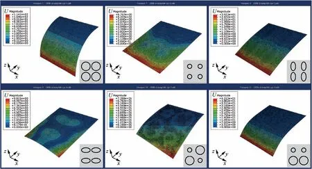
Fig. 1 Morphing states with different bi-stable regions (Aluminum, plastic strain εp=3000×10-6).
2. Materials
As multi-stable nanomaterials can realize large continuous deformation,it has great potential to be applied to the morphing wing. In this section, the design scheme and preparation process of an aluminum-based multi-stable nanomaterial were disclosed. A continuous morphing wing concept based on this multi-stable material was proposed.
2.1. Preparation of bi-stable nanomaterial
In this research,the SMAT technology was used for the preparation of bi-stable nanomaterials.SMAT is an authorized technical patent which can dramatically improve the mechanical properties of metal materials using chaotic ball impact,invented by Lu K and Lu J.41Recently, Yi et al.42–44found metal sheets, such as steel, aluminum, magnesium, etc., can obtain local bi-stable property after alternatively processing on both sides using SMAT. The formation mechanism of the bi-stability is due to SMAT induced local residual stress. The more the residual stress is induced, the larger the force is needed to trigger the transformation between two stable states.In other words, the larger the trigger force is, the stronger the load capacity is.Besides,coupled with the increase of deformation ability is the improvement of mechanical property in bistable regions, such as the enhancement in strength and resistance to corrosion. Viewed under an electron microscope, Ya et al. found that the surface layer of the bi-stable region exhibits gradient nanostructure which is the decisive factor to improve mechanical properties.45In addition to the advantage of mechanical property, compared with the current bi-stable materials, the bi-stable nanomaterial can be easily used for the multi-stable morphing by designing multiple bi-stable regions on a metal sheet.
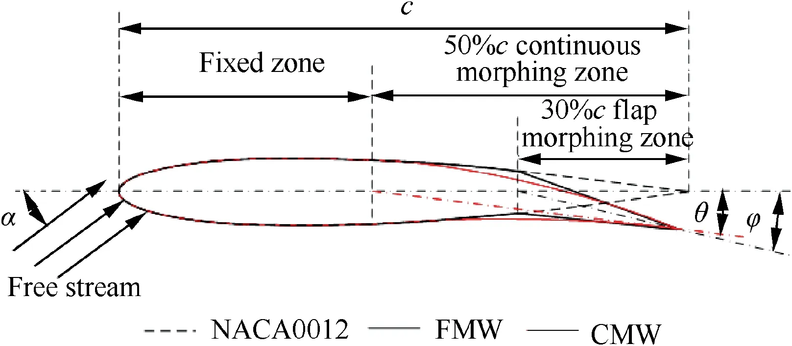
Fig. 2 Conceptual design of the CMW.
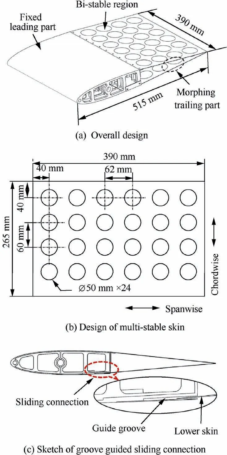
Fig. 3 Design of the CMW.
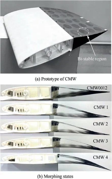
Fig. 4 Prototype and morphing states of the CMW.
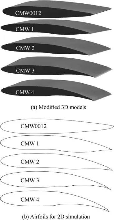
Fig. 5 3D and 2D models of each stable state.
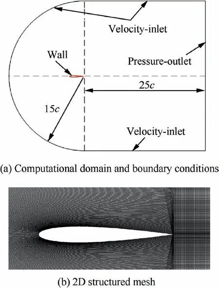
Fig. 6 Computational domain, boundary conditions, and 2D structured mesh.
2.2. Design of multi-stable nanomaterial
As mentioned in Section 2.1,the design concept of multi-stable nanomaterials is based on the number and the arrangement of bi-stable regions.46As a bi-stable region has two stable states,a sheet with n bi-stable regions should possess 2nmorphing states in theory. Besides, the shape and size of each bi-stable region and the array format will similarly affect the morphing results. As shown in Fig. 1, the simulation results show that different shapes (circle and ellipse), sizes, array formats and combinations of the bi-stable regions will lead to different morphing results, where U represents the absolute node displacement of each case.Therefore,these multi-stable nanomaterials can provide researchers more options for morphing applications in aviation and other engineering fields.
In this study, to simplify problems, the material design follows a principle that the number, shape and distribution pattern of bi-stable regions are fixed with a single form.Moreover, to make the design close to reality, an aircraftgrade aluminum alloy of 6061 sheet,which is the main material for wing skin, was chosen as the raw material. 3 mm diameter 304 stainless steel balls were used to irregularly impact the aluminum alloy sheet surface.In any morphing state,the material does not need any external force to maintain stability. But when the external force exceeds a certain limit, the current stable state will transform into another stable state with a snap-through phenomenon. The force to trigger the snap-through phenomenon can be designed by controlling the residual stress. The designed multi-stable nanomaterial can realize upward/downward chordwise deflection and spanwise twist to simulate the corresponding functions of flaps and ailerons.
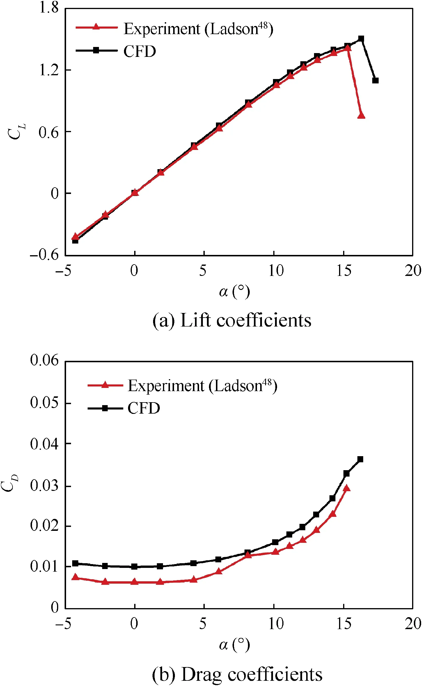
Fig.7 Comparison between CFD results and experimental data.
3. Model and methods
A CMW model based on the multi-stable nano aluminum alloy sheet was designed and fabricated. CFD simulation method was adopted to study the aerodynamic performance of this morphing wing.
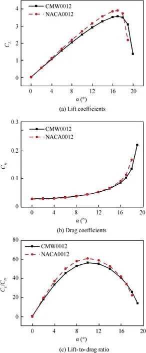
Fig. 8 Comparison between CMW0012 and NACA0012.
3.1. Conceptual design
The wing with a continuous and seamless morphing trailing part was designed based on the NACA0012 airfoil.The design concept of the CMW is shown in Fig. 2. To increase the morphing ability, the morphing part was designed as nearly 50%chord length (c) of the NACA0012 base airfoil. Traditional rear-mounted flaps and ailerons were replaced with the morphing trailing part which was assembled with two monolithic multi-stable nano aluminum alloy skins. In Fig. 2, φ is the deflection angle of the traditional 30% chord-length Flap Morphing Wing (FMW). The deflection angle θ of CMW is defined as the angle between the chord lines of the base airfoil(NACA0012) and the morphing trailing part. The angle between the chord line of the base airfoil and the flow direction of the free stream is the angle of attack α.
3.2. Prototype fabrication
Considering the follow-up wind tunnel test,the overall dimensions of the morphing wing were designed as 390 mm in wingspan and 515 mm in chord length as shown in Fig. 3(a). The chordwise length of the morphing section is 265 mm took up nearly 50% of the chord. 24 circular bi-stable regions are uniformly distributed on both upper and lower skins in a 4×6 matrix as shown in Fig. 3(b). To simplify the morphing problem and only consider large deflection states, bi-stable regions in the same spanwise line were simultaneously controlled for every actuation. As the number of bi-stable regions along the same chordwise line is 4, a total of 4 downward deflection states were mainly studied. The upper and lower multi-stable skins were fixed together at the trailing edge. For the connection methods between the morphing trailing part and the fixed leading part, mechanical fixed connection and groove guided keep a complete aerodynamic configuration at this stage, a light-weight 3D printing leading part with a smooth contour was selected.These two parts could be assembled or disassembled easily. Fig. 4(a) shows the prototype of the CMW. To facilitate the expression of each state of the CMW, the initial state together with 4 downward morphing states, with the increase of θ, are named CMW0012, CMW 1, CMW 2,CMW 3 and CMW 4 shown in Fig. 4(b).
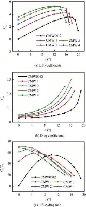
Fig. 9 Aerodynamic performance of CMW.
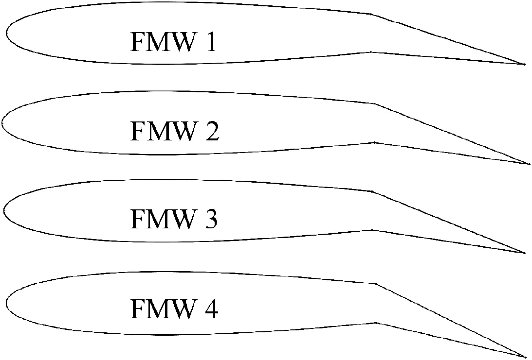
Fig. 10 Morphing states of FMW.
3.3. Numerical analysis and validation
3D scanning was used to capture the details of the multi-stable configuration which makes the numerical model close to reality. The Industrial 3D scanner Artec Space Spider with a precision of up to 0.05 mm used here can accurately record the configuration parameters of each stable state. The scanned models were reasonably optimized with the removal of those unimportant features introduced during scanning work in the premise of guarantee calculation precision. The reasonably modified models can be directly used for 3D simulation or intercepted to get airfoils for 2D simulation as shown in Fig.5.
In this numerical analysis, flow around morphing airfoils was simulated by solving the steady turbulent incompressible 2D Navier-Stokes equations. Spalart-Allmaras turbulence model which is mainly designed for aerospace applications was used to solve this problem. The second-order upwind scheme, second-order central difference scheme, and coupled algorithm47were selected for each parameter setting, respectively. The computational domain was built large enough to reduce the boundary effect as shown in Fig. 6(a). In Fig. 6(b), 2D structured mesh with a refined grid in the boundary layer was adopted to improve computing accuracy. The settings of the boundary conditions are depicted in Fig. 6(a).
To verify the feasibility and accuracy of the calculation,simulation results (lift coefficient CLand drag coefficient CD)of the airfoil NACA0012 were compared with the experimental data published by NASA.48All the parameters in the simulation are consistent with the wind tunnel test. The chord and the span of this validation model respectively are 60.10 cm and 91.44 cm. The range of the α is set up from -4.25° to 18.25°. The Reynolds number and the Mach number are selected as 2×10⁶and 0.15, respectively. Finally, the feasibility and veracity of the numerical method adopted in this research were verified by the comparison results.
As shown in Fig. 7, the lift coefficients calculated from the numerical simulation are consistent with the experimental results except for the stalling angle. As the drag coefficients are difficult to be precisely predicated using the Spalart-Allmaras model, the simulation results are a little bit larger than that of experiments. However, the general trend of CDfrom the simulation is consistent with that from the experiment. As the CFD method is mainly used for the comparison of two simulation models,in this study it is sufficiently precise for predicting the aerodynamic performance of the CMW.
4. Results and discussion
sliding connection were adopted for the upper and lower junctions respectively. The sketch of this sliding connection is shown in Fig. 3(c). This sliding design plays a crucial role in the overall design because it can provide a deformation allowance for the wing morphing. As the leading part only helps to
This section provides the numerical simulation results for the aerodynamic performance of the CMW. The superiority of the CMW is discussed through the comparison with the traditional FMW.
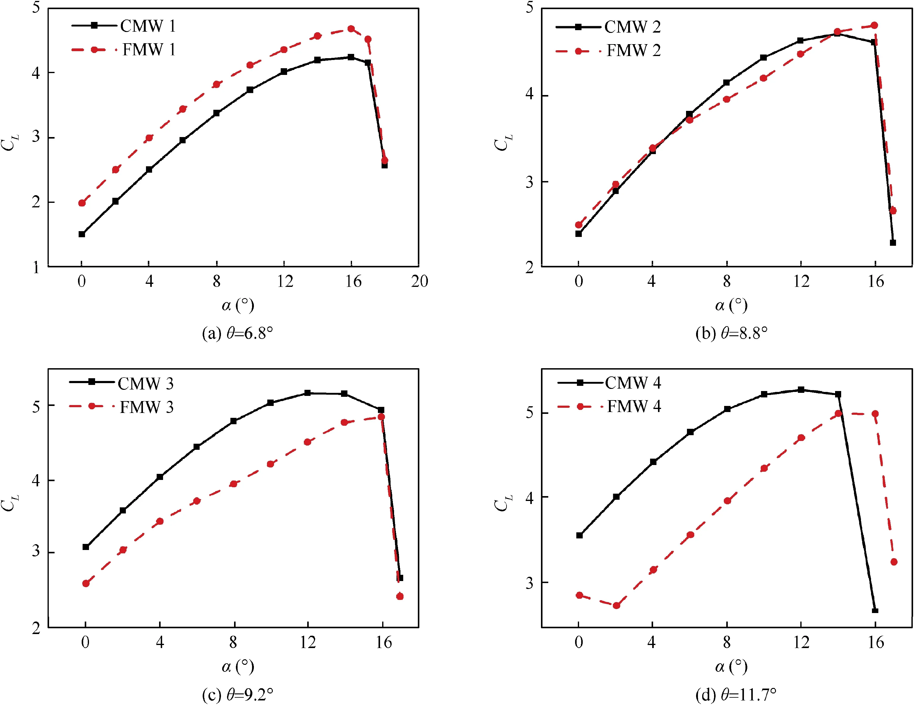
Fig. 11 Comparison of lift coefficients.
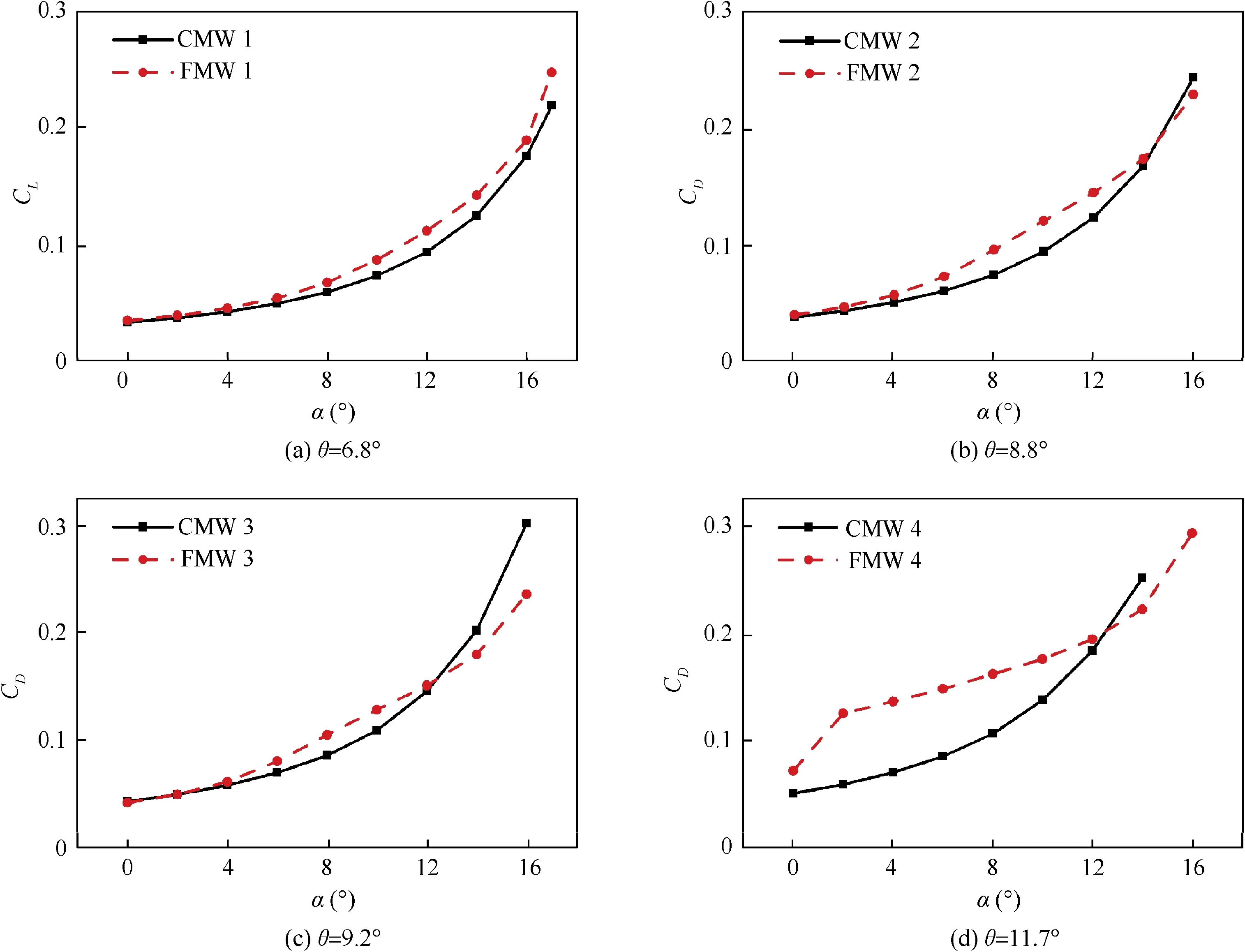
Fig. 12 Comparison of drag coefficients.
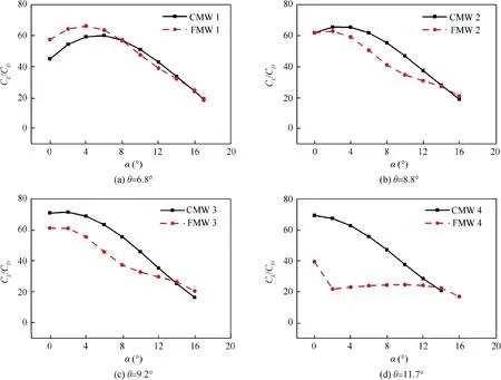
Fig. 13 Comparison of lift-to-drag ratio.
4.1. Aerodynamic performance analysis of CMW
To study the influence of α and θ on the aerodynamic characteristics of the CMW,the 5 airfoils listed in Fig.5(b)were simulated. The deflection angles of the 5 airfoils are measured as 0°, 6.8°, 8.8°, 9.2°, and 11.7°, respectively. The range of the α is set from 0°to 20° with an interval of 2°. The Mach number and the Reynolds number are 0.17 and 2×10⁶, respectively.
4.1.1. Aerodynamic performance verification before morphing
The initial state of the CMW before morphing was predesigned as NACA0012 airfoil.To verify the fabrication accuracy of the initial model, CFD simulation results of both CMW0012 and NACA0012 were compared shown in Fig. 8.And obviously, the results of CL, CDand lift-to-drag ratio(CL/CD) for both models are very close that the relative deviation of each parameter is less than 10%. It proves that the configuration of CMW0012 is almost the same with its base airfoil NACA0012. As for some specific differences, it’s likely caused by machining error which can be reduced by correction.
4.1.2. Aerodynamic performance analysis during morphing
Fig.9 shows the simulation results of the 5 stable states of the CMW.As you can see in Fig.9(a)and(b),both the CLand the CDare increased with the deflection of the wing as expected.To study the aerodynamic efficiency of these 5 states, the CL/CDwas calculated as shown in Fig. 9(c). It is interesting to observe that, the CL/CDincreases with the increase of the θ at a small range of α (0–8°), while it reserves when the α is over 8°.Besides, the CL/CDof the CMW4 is smaller than that of the other 3 morphing states when the α is 8°. This phenomenon indicates that even if the α is small,the CL/CDwould not increase infinitely along with the increase of the θ.
4.2. Advantage analysis of CMW compared with FMW
To validate the CMW is better than the traditional FMW in aerodynamic performance, 4 corresponding morphing contours of the FMW were modeled according to the relationship between θ and φ depicted in Fig. 2. Fig. 10 shows the 4 morphing airfoils of the FMW.After repeating a series of uniform simulation procedures as Section 4.1, the comparison results are detailed described as follows.
As shown in Fig.11,the CLrelationship between two models in any morphing state varies greatly.In Fig.11(a),the CLof the FMW is larger than that of the CMW at a small deflection angle of 6.8°.While,when θ increases to 8.8°,the CLvalues of both models are almost the same as shown in Fig. 11(b). In Fig. 11(c) and (d), as the deflection continues, the unexpected results in Fig. 11(a) has been reversed where the CLof the CMW becomes larger. The CLof the CMW4 increases by up to 46.7% than the FMW4 at a small α of 2°. It can be concluded that the lift-enhancement effect caused by continuous morphing is more apparent at larger deflection angle conditions. As for what causes the results in small morphing states(CMW 1 and CMW 2), the explanation will be explored in the analysis of the flow field.
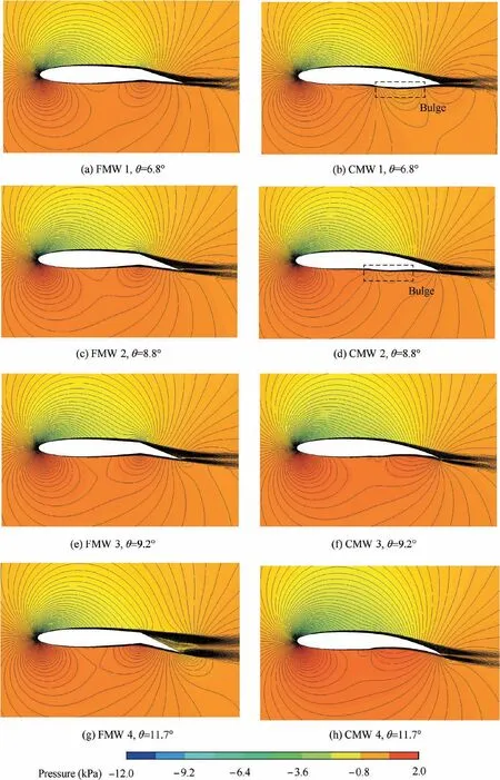
Fig. 14 Comparison of pressure and velocity fields (α=4°).
To compare the aerodynamic efficiency of the two morphing ways,the CDis another important parameter to be studied.It is observed from Fig. 12 that, compared with continuous morphing, overall, the flap morphing wing creates more drag.The drag reduction effect of the CMW is more remarkable especially at small θ (Fig. 12(a) and (b)). The CMW 1 and CMW 2 can realize up to about 20% drag reduction in some conditions. Even at large θ in Fig. 12(c) and 12(d), it works for most of the α. For example, the drag reduction effect of the CMW 4 is more obvious at a small angle of attack. The reduction effect of the CMW 4 is amazing which can be up to 50%.A possible reason for the performance of drag reduction here is speculated that the CMW can influence the flow separation.This speculation will be further verified in the flow field analysis in the following Section 4.3.
The CL/CDresults of the two morphing ways depicted in Fig. 13 are used for evaluating the aerodynamic efficiency.What is clear from Fig. 13(a) is that the advantage of the CMW is not obvious at small θ, and even worse when α is small. However, with the increase of θ, the superiority of the continuous morphing has emerged as shown in Fig. 13(b)–(d). Compared with the FMW 4, the CL/CDof the CMW 4 is significantly improved, and the maximum increase can be 200%.Therefore,it’s not hard to see that the aircraft can benefit directly from the high lift-drag ratio profit brought by this continuous morphing method.
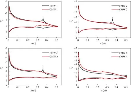
Fig. 15 Comparison of pressure coefficients (α=4°).
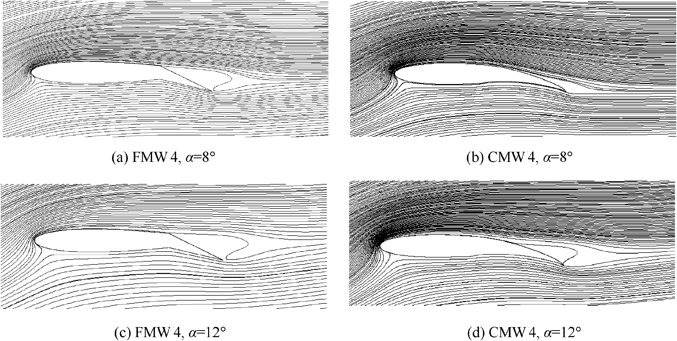
Fig. 16 Comparison of streamlines.
4.3. Flow field analysis
The detailed results in various forms above could be explained by the clues hidden in flow fields.As shown in Fig.14,pressure(color map) and velocity (black lines) fields of the FMW and the CMW are compared in visualization. The CLrelationship of each morphing state in previous sections can be verified by the intensity of the color. When the α is small (4° in Fig. 14),the CLof both wings increases with the θ increase as the color of the pressure field beneath the wing gets darker.Besides,the color difference of both wings in the same morphing state also proves the previous CLresults in Fig. 11. The observation shows that the local bulge under the CMW caused by the deformation theory of the multi-stable skin is probably the reason for pressure reduction. It makes sense that the CLof the CMW gradually exceeds its counterpart when the bulge becomes small or disappears with the increase of θ.To further demonstrate the CLresults, the pressure coefficient (Cp) relationships are depicted in Fig. 15. x is the displacement along the chordwise direction from the leading edge.The Cpdistributions on both upper and lower wing surfaces directly confirm the aerodynamic characteristics that the pressure fields reflected in Fig. 14. It’s not hard to see the initial position of the flap morphing can cause pressure concentration which is easy to induce flow separation.
Also, the velocity fields in Fig. 14 show that the CMW has more advantages on drag reduction than the FMW,especially in large θ conditions, which is also consistent with the results shown in Fig.12.Flow separation is suppressed,and the location of separation initiation is also delayed due to continuous and moderate morphing. This phenomenon can be further clearly observed from the streamlines of the FMW 4 and the CMW 4 at middle-higher angles of attack (8° and 12°) shown in Fig. 16. Quite obviously, the drag reduction happens in the suppression process of separation vortices.
Another interesting result in Fig. 12 that the CDof the CMW is larger than that of the FMW at a high angle of attack around stalling angle and large deflection angle. The spatial streamlines in Fig.17 will help to understand how this happens at the same α of 16°. As you can see in Fig. 17(a) and Fig. 17(b),the extent of flow separation is almost the same at a small deflection angle (θ=6.8°). However, from Fig. 17(c) to Fig. 17(f), when θ increases, the flow separation of the CMW is enhanced greatly, and even causes stall. The most likely cause is that this 50% chord-length morphing design of CMW will exacerbate the flow separation problem at a high angle of attack due to a wide-range smooth deformation without any resistance just like the sharp edge flap formed during work.
In a word,from the above analyzing,there is no doubt that the CMW can provide better aerodynamic performance for the aircraft. The CMW has evident superiority over the FMW in most cases. Those special failed cases are also useful for determining the range of operation and deserved further study.
5. Conclusions
A continuous morphing trailing-edge wing based on a multistable nanomaterial was fabricated and numerically analyzed in this study. The steady aerodynamic characteristics of different morphing state with different α and θ were studied.Contrastive analysis of aerodynamic efficiency between the CMW and the FMW was conducted. Flow field analysis provided more intuitive evidence to explain the mechanism behind the results. Some discoveries in this study are as follows:
(1) With an increase of θ, the CLand CDincrease accordingly. But the CL/CDincreases only at the small α flight condition. Therefore, the CMW can provide more choices to adapt to different flight conditions or missions.
(2) The CMW can generate larger CLthan the FMW when the θ amounts to a certain degree. In most cases, the CMW generates less drag than that FMW does. Therefore, at the same flight condition, the overall aerodynamic efficiency of the CMW is superior to the FMW.
(3) At the small-middle angle of attack, the CMW can suppress the flow separation and reduce separation vortices.This benefit will be more obvious especially in large deflection states.
Acknowledgments
The authors acknowledge the supports of the National Key R&D Program of China (No. 2017YFA0204403). This work is supported by the Major Program of National Natural Science Foundation of China (No.: NSFC51590892) and the Shenzhen Municipal Science and Technology Innovation Commission of China (No.: JCYJ20160229165310679).
 CHINESE JOURNAL OF AERONAUTICS2021年7期
- CHINESE JOURNAL OF AERONAUTICS的其它文章
- Integrated batteries layout and structural topology optimization for a solar-powered drone
- Polynomial networks based adaptive attitude tracking control for NSVs with input constraints and stochastic noises
- Morphing wing flaps for large civil aircraft:Evolution of a smart technology across the Clean Sky program
- Review on bio-inspired flight systems and bionic aerodynamics
- SARISTU:Adaptive Trailing Edge Device(ATED)design process review
- A hybrid multidimensional Riemann solver to couple self-similar method with MULTV method for complex flows
