Integrated batteries layout and structural topology optimization for a solar-powered drone
Zijin ZHANG, Ruitong ZHANG, Jihong ZHU,c,*, Tong GAO,c,Fei CHEN, Weihong ZHANG
a Institute of Engineering Thermophysics, Chinese Academy of Sciences, Beijing 100190, China
b State IJR Center of Aerospace Design and Additive Manufacturing, School of Mechanical Engineering, Northwestern Polytechnical University, Xi’an 710072, China
c Institute of Intelligence Material and Structure, Unmanned System Technologies, Northwestern Polytechnical University,Xi’an 710072, China
KEYWORDS Geometrical nonlinearity;Integrated optimization;Lithium batteries layout;Periodic structural configuration;Solar-powered drone;Wing beam structure
Abstract The purpose of this paper is to demonstrate an integrated optimization scheme for a solar-powered drone structure. Consider a primary beam in the wing of large aspect ratio, where 100 lithium batteries are assembled.In the proposed integrated optimization,the batteries are considered here as parts of the load-carrying structure. The corresponding mechanical behaviors are simulated in the structural design and described with super-elements. The batteries layout and the structural topology are then introduced as mixed design variables and optimized simultaneously to achieve an accordant load-carrying path.Geometrical nonlinearity is considered due to the large deformation. Different periodic structural configurations are tested in the optimization in order to meet the structural manufacturing and assembly convenience.The optimized designs are rebuilt and tested in different load cases.Maintaining the same structural weight,the global mechanical performances are improved greatly compared with the initial design.
1. Introduction
A solar-powered drone of large aspect ratio can fly and service in near space.Solar cells assembled on the skin can provide its power during the day time.Meanwhile,lithium batteries in the wing box will be charged at the same time to provide energy for night flight. In this case, in order to ensure the aircraft can fly long time across the day and night,the global structural system of a solar-powered drone must be designed ultralightweight and compliant, which becomes a great challenge to the aircraft structure design.1
To save the weight for the structural systems, topology optimization has been widely used in aircraft design.2–7The conception was also implemented in structure design of solar-powered drones,8,9 where certain weight reduction effects were obtained. However, the batteries layout of a solar-powered drone was mostly considered in the energy management design.10–12While during the structural design, the batteries were only modeled as some concentrated masses or even ignored,whose mechanical behaviors were hardly considered.13–15These works actually did not give full play to the potential of the system layout in terms of structural loadcarrying.
In fact, lithium batteries and their packages have considerable mechanical properties,which can be considered as a structural component and designed together with the structural configurations. An integrated optimization scheme was proposed16–19to synchronize the components layout and structural topology design. This idea has been widely accepted in aircraft and aerospace structure systems design. Later, the components shape and topological changes were further described by mean of level set model with more accurate and smooth geometrical description.20,21Further extensions of the integrated optimization were found in some recent work,such as feature driven design22,23and smart structure system design.24,25
In this paper, the idea of integrated optimization will be further developed to obtain effective designs for wing beam structure system of an under development solar powered drone, making full use of the mechanical potential of the lithium battery packages and considering geometrical nonlinearity and different periodic structural configurations.
2. Optimization model and basic formulations
2.1. Optimization model of the wing beam
The concerned solar powered drone is an unmanned aircraft of large aspect ratio. The global structure can be seen in Fig. 1,which is a typical blended wing body containing 6 electric engines. The aircraft has a large wing area, a small fuselage weight and a quasi-uniformly distributed lift on the wing.The solar cells are distributed on the upper skin of the wing.There are two primary beams in the wing and 100 lithium battery packages are evenly assembled on the 25 sections of the front beam between the root of the blended wing body and the outer wing sections, as magnified in Fig. 1.
In order to achieve an extremely lightweight structure design, it is necessary to make full use of the load carrying potential of each battery package on the one hand,and ensure that the lift and gravity of the wing are mostly balanced in each section on the other hand. As a result, we can find the wing adopts a nearly periodic structural configuration for the sections,and the distribution of the battery extends from the root to close to the wingtip. The optimization will be carried out mainly focused on these structures.
The design domain contains the front beam structure and the assembled battery packages. As shown in Fig. 2, these 25 wing sections are taken out from the global structure as the design model. The beam web of each section is designed periodically in the wingspan direction to favor the manufacturing and assembling. For aircraft of large aspect ratio, extreme requirement on structural lightweight design results in considerable structural flexibility. In order to ensure the structural integrity and maintain the global aerodynamic shape,it is necessary to restrain the structural deformation under the primary load conditions on the one hand.The corresponding loads and boundary conditions are equivalently obtained from the global structure using the sub-structuring method26,27considering the cruising flight, level maneuver, descent and climbing. 3 static Loading Conditions (LC), i.e. bending, twisting and 3 times acceleration of gravity are therefore applied on the structure with these sections fixed to the aircraft body.A normal gravity is also applied in the first two static conditions.
On the other hand, the aircraft structure of large flexibility has very low natural frequencies. It is very likely to produce unfavorable coupling with wing structures’ rigid body motion and induce structure flutter. As a result, the first 3 orders of natural frequencies are considered. Assigning aluminum alloy 7075 as the material,the model is meshed with refined shell elements and analyzed. Note that in existing aircraft structure design using equivalent lumped mass elements instead of real batteries, the structural mechanical performances are underestimated as the batteries’stiffness is ignored. Here the batteries are considered here as structural components, whose stiffness and mass properties are taken into account simultaneously and precisely in the static and dynamic performance analysis.The results for each load conditions are presented also in Fig.2.As the maximum deformation in the 3 static load cases reaches 5 m,which is more than 20%of the beam length,geometrical nonlinearity is considered here and the load increment is 1/30 of the total external loads.
2.2. Basic formulations of the integrated optimization
In the integrated optimization, two different kinds of design variables, i.e. The pseudo-density variables describing structural topologies and the geometry variables indicating the locations and orientations of the batteries are involved, which can be expressed as:

Fig. 1 Solar-powered drone and its wing beams with lithium battery packages.

Fig. 2 Design model, load conditions and analyzed results of the initial design.

where η is the set of pseudo-density variables.ηeis the pseudodensity variable of the eth element, Nddenotes the number of the pseudo-densities. s is the set of geometry design variables.sjx,sjyand sjθare the geometry design variables of the location and orientation related to the jth battery.NBdenotes the number of batteries.Note that the periodic configurations are used for the design domain, one designable, geometry or pseudodensity, relates to corresponding batteries or elements in 25 wing sections.
In this study,to save the computational cost involved in the finite element analysis, batteries may be considered as substructures as their interior mechanical responses are relatively less concerned in this work. As a result, they can be modeled as super-elements as illustrated in Fig. 3, only the d.o.fs associated with boundary nodes are retained while the interior d.o.fs are condensed.The reduced stiffness matrix can be expressed as

KSis the reduced stiffness matrix of the super-element.KBis the original stiffness matrix of the battery,which is partitioned into blocks according to the interior d.o.fs and the boundary d.o.fs.Kiiis the stiffness matrix of interior nodes,Kbbis the stiffness matrix of boundary nodes, Kiband Kbiare coupling stiffness matrix. Moreover, when a battery has a translation motion during optimization, its super-element stiffness matrix remains unchanged. But when it rotates an angle θ to other orientations, the stiffness matrix KS(θ) can be analytically calculated as a function of its orientation by means of the coordinates transformation matrix T(θ). Note that KS(0) is the original stiffness matrix without rotation.

In this way, the stiffness matrices of the super-elements for all the batteries can be calculated only once.
Then we consider the connections between the battery packages and the wing beam.In the original design,the battery packages have been located horizontally in earlier system layout design and energy management design for their convenient. A customized bonding structure is used to assemble the packages, which is not an effective load-carrying solution.

Fig. 3 Definition of super-elements and their condensing d.o.fs.
To fully use the mechanical properties of the battery packages, we redesigned the case of the package, prescribing four connection positions on each package for installation as shown in Fig. 4. We build MPCs as the connections. The wing beam and the battery packages are discretized respectively into finite elements.Assume P1is one of the connecting nodes on the battery package, which is projected to the point P1* inside the wing beam element e1. Then we enable the following Multi-Point Coupling (MPC) equation.

As MPC equations are linear combinations of the finite element nodal displacements, multiple MPC connections,together with the boundary conditions, can be organized as a formulation of linear equations.

H is a coefficient matrix, which can be determined by the shape functions of the corresponding elements of MPC connections and the boundary conditions. u is the finite element nodal displacement vector. The above equation can be recognized as displacement constraints in finite elements.By revising the form of the overall potential energy, the static finite element equilibrium can be express as

where λ is the Lagrange multiplier vector. Fextis the external nodal load vector and Fintis the internal nodal load vector. r is the residual in obtaining the nonlinear structural equilibrium.
Similarly, a dynamic problem with MPC can be expressed as:

where K and F are structural global stiffness matrix and nodal load vector, respectively. M and C are the mass matrix and damping matrix respectively. We only consider natural frequency problem in this work,so the damping matrix and force excitation do not take effect.
According to the load conditions considered in the last section, we assign the sum of the complementary elastic work of external forces in the 3 static load conditions as the objective function to be minimized. The optimization design turns out to be mostly a nonlinear stiffness maximization, where lc marks different load conditions.
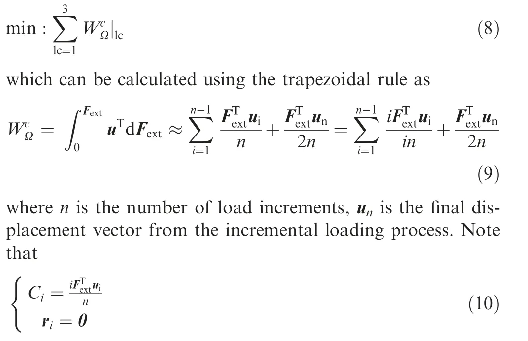
are the end-compliance and residual of the ith load step. We also have the end-compliance of the nth load step equal to the overall end-compliance, which is

Meanwhile, the first 3 orders of natural frequencies shall not be less than those of the original design.

A volume fraction constraint and geometrical constraints avoiding batteries’ overlapping is also assigned to the design domain.

V and VUare the solid volume fraction and its upper bound, respectively. The Finite-Circle Method (FCM)17is adopted here to define the geometrical constraints. FCM uses a series of circles to approximate both battery packages’ profiles and design domain boundaries. Non-overlapping constraints can be described as distance constraints between different circles. xim, yimand rimare coordinates and radius of the center of mth circle on ith component respectively. xin,yinand rinshare similar definitions. gkdenotes the kth nonoverlapping constraint.
The structure in this work subjects to inertial and dynamic loads, the popularly used Solid Isotropic Material with Penalization (SIMP) model will probably lead to localized modes when pseudo-density variable takes a small value in the lowdensity area. Alternative interpolation schemes such as Rational Approximation of Material Properties (RAMP)28and Polynomial Interpolation Scheme (PIS)17can effectively eliminate the localized modes. PIS is adopted here.

Fig. 4 Redesigned package case with four connection positions and their MPC connections.

where, Meand Kedenote the mass matrix and the stiffness matrix of eth element respectively. Me0and Ke0are the mass and stiffness matrices of a corresponding element with fully solid material.
The sensitivity analysis of the objective function will lead to the derivative of the stiffness matrices, the mass matrices, the Polynomial Interpolation Scheme and the MPC coefficient matrix with respect to the pseudo-densities and batteries’geometry variables. The similar derivation can also be found in previous works.18
Then we consider the derivative of the complementary elastic work, which can be calculated from the end-compliance of each load step according to Eqs. (9) and (10). We have the Lagrangian function and its derivative of the end-compliance:

Suppose x is one of the design variables, the derivative of the load vector can be easily obtained when we consider gravities linking to the element mass. We also have the tangent stiffness matrix KTexpressed as

Then the derivative of the end-compliance can be further expressed as
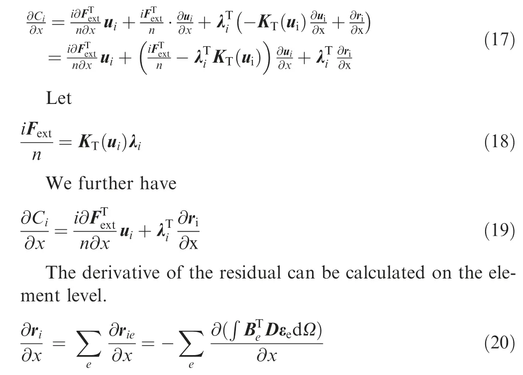
where Be,D,εeare the geometry matrix,material elastic matrix and strain vector of the eth element. When the design variable x is a pseudo-density variable, the above derivatives of the external loads and the residual can be derived according to the differentiation of interpolation scheme in Eq. (14). But when x is a geometry design variable,we have to use finite difference to calculate the derivatives of the external loads and the residual.
Moreover, to achieve the tangent stiffness matrix, we propose to use a semi-analytical scheme. Suppose there are two load steps i-1 and i, when the load increment is small enough, we can assume the tangent stiffness matrices are approximately equal

So we have

In this way, we can assume an adjoint structure with its stiffness matrix be the tangent stiffness matrix,its deformation response under the external load can be obtained by calculating uiand ui-1.
The we consider the sensitivity of the natural frequencies.The dynamic problem in Eq. (7) becomes an eigenvalue problem. The sensitivities can be derived as

where uiis the ith eigenvector, and

Note that the second term of Eq. (23) is zero. The sensitivities can be further derived as

When the design variable x is a pseudo-density variable,the above derivatives of the stiffness matrices and the mass matrices can be derived according to the differentiation of interpolation scheme in Eq. (14). But when x is a geometry design variable, we also need to use finite difference to obtain the derivatives approximately.
3. Integrated optimizations
3.1. Pure periodic design
Firstly, we consider the same situation of pure periodic design as the initial design, where all the beam structures topology and batteries distribution using the same configuration in 25 wing sections. The four battery packages are initially located horizontally in each section of design domain. 40% of the material volume is used. The optimization procedure and iteration history are shown in Fig. 5.
The optimization is carried out using the optimization algorithm GCMMA (Globally Convergent Method of Moving Asymptotes)29implemented in the general-purpose design platform Boss-Quattro.30During the optimization, the structural topology on the beam web evolves to a complicated cantilever beam. The battery packages relocate their positions simultaneously and join the beam structure as a loadcarrying integrity. All the design constraints are satisfied. As the topology results are not clear enough,the optimized objective function value and constraint values make no sense compared with the initial design.
Therefore,according to the final design reached at the 47th iteration,this configuration is redesigned in CAD and put into the wing beam sections periodically. Using refined shell elements, the optimized design’s deformations in 3 static load cases and natural frequencies are shown in Fig. 6.

Fig. 5 Iteration (Iter.) history of the integrated optimization.
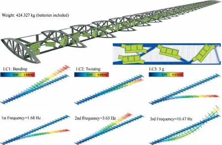
Fig. 6 Pure periodic optimization design and its analyzed results.
Compared with the initial design, the total weight of the optimized design barely changes. The maximum deformations in 3 static load cases decrease from 2.32 m, 1.04 m, 5.30 m to 1.84 m,0.86 m,4.17 m.The first 3 natural frequencies increase from 1.48 Hz, 3.24 Hz, 9.21 Hz to 1.68 Hz, 3.63 Hz, 10.47 Hz.It is clearly shown that the global structural stiffness has been greatly improved by relocating the battery packages matching the structural topology.Moreover,the material mass distribution has been optimized to a more coordinated configuration,which lead to the increasing of the natural frequencies.
3.2. Free optimization without periodicity
Structural periodicity in different sections favors manufacturing and assembling. However, this is a great limitation to the structure design which prevents the optimization reaching better results.Here we test a free integrated optimization without periodicity, where the material and battery packages can be located freely in the wingspan direction. The design domain becomes a long beam with large slenderness, which is also cut by the wing rids into 25 sections.The optimization reaches its convergence at 126th iteration. The optimized design is shown in Fig. 7. Consider the length of the beam, it is separated into several rows for a clear presentation.
In the above optimization results,more batteries and material are trying to locate near the root of the wing where it is fixed to the aircraft body. This is reasonable due to the cantilever beam design nature. The requirements on the natural frequencies and deformation under gravities will also drive heavy objects to the fixations.
The optimized designs are rebuilt into CAD model and analyzed again with refined shell elements. Deformations in 3 static load cases and natural frequencies are shown in Fig. 8.Compared with the pure periodic optimization design, the total structural weight is almost unchanged. The deformation pattern and vibration mode have no significant change in these and above optimization designs. The maximum deformations in 3 static load cases decrease from 1.84 m, 0.86 m, 4.17 m to 1.68 m,0.72 m,3.22 m.The first 3 natural frequencies increase from 1.68 Hz,3.63 Hz,10.47 Hz to 1.83 Hz,3.96 Hz,11.01 Hz.It is obvious that the structural performance has been improved by removing the periodic condition.
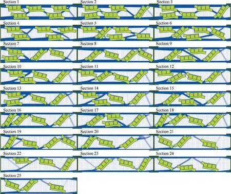
Fig. 7 Integrated optimization without periodicity requirement.
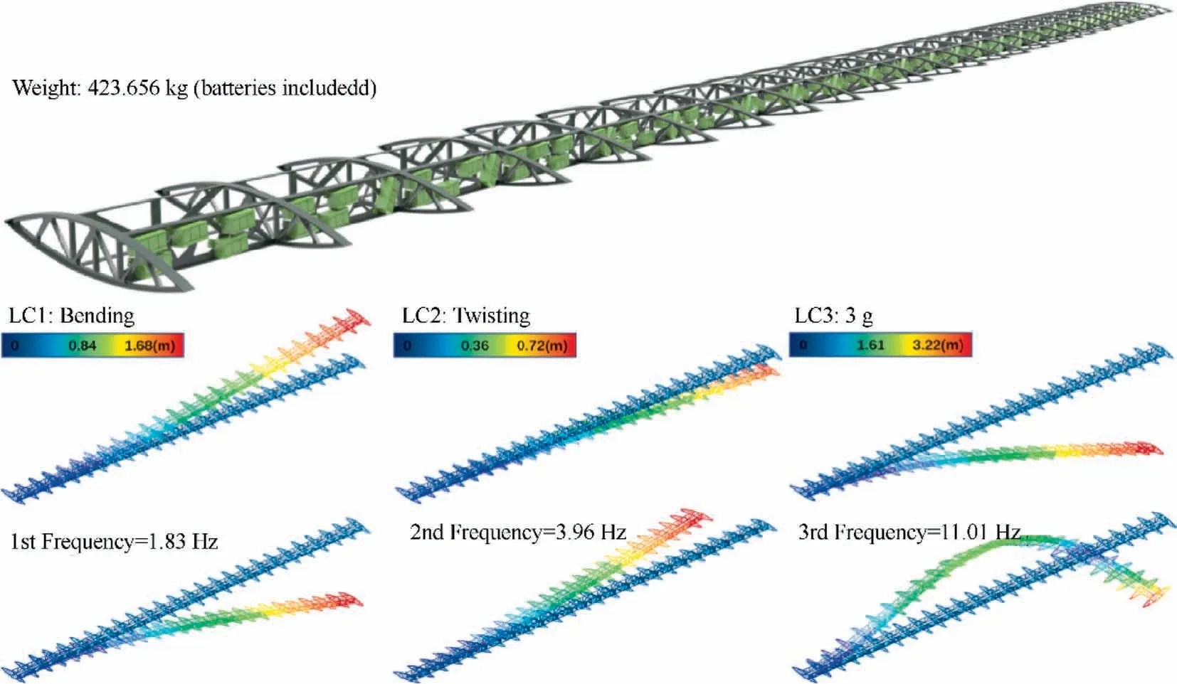
Fig. 8 Optimized design without periodicity requirement.
3.3. Segmentally periodic optimization design
Although the free optimization brings more flexibility and improves the global mechanical performance significantly,the manufacturing and assembling cost will increase exponentially.We can make a compromise and consider a segmentally periodic optimization design. Review the optimized designs obtained by the free integrated optimization, we found there are 5 battery packages located in the first 6 sections and only 3 located in the last 6 sections.Meanwhile,the material volume in each section gradually decreases from more than 50% to about 25% percent.
Consequently, we decide to separate the wing beam into 3 segments with 3 different periodic configurations. Count from the root of the wing, the first 6 sections will have 5 battery packages and 50%volume fraction. The following 13 sections will have 4 battery packages and 40% volume fraction. The last 6 sections will have 3 battery packages and 30% volume fraction.
Using the above definition of segmentally periodic optimization, the optimized designs are shown in Fig. 9 and are rebuilt into CAD model and analyzed again. Deformations in 3 static load cases and natural frequencies are shown in Fig. 9.
Results from the 4 different designs are listed in Table 1 for comparison. The numbers of iterations and computing time are also compared in Table 2. The 3 different optimized designs have improved the mechanical performances of the wing to different degrees. It is clearly shown that the results and the computing cost of the segmentally periodic optimization are just between the periodic design and free optimization,which balances the mechanical performance and manufacturing convenience.
Moreover, it should be mentioned that the structural weight is kept almost constant during the above optimization designs. It is commonly accepted that lightweight design is essentially important for aircraft structure. In the process of structure design, lightweight is usually achieved through two different design modes:weight priority and performance priority. Under the weight priority mode, the designer achieves the initial design satisfying the weight index of each part pre-scribed by the system design. A subsequent optimization will improve the mechanical performance of the structure to a satisfactory level,maintaining a constant structural weight.In the performance priority mode, the designer achieves an initial structure that satisfies the mechanical performance. Optimization will realize the weight saving.The two modes usually end up with similar results and can be used in combination during design modifications and iterations.

Table 2 Comparison of the numbers of iterations and computing time.
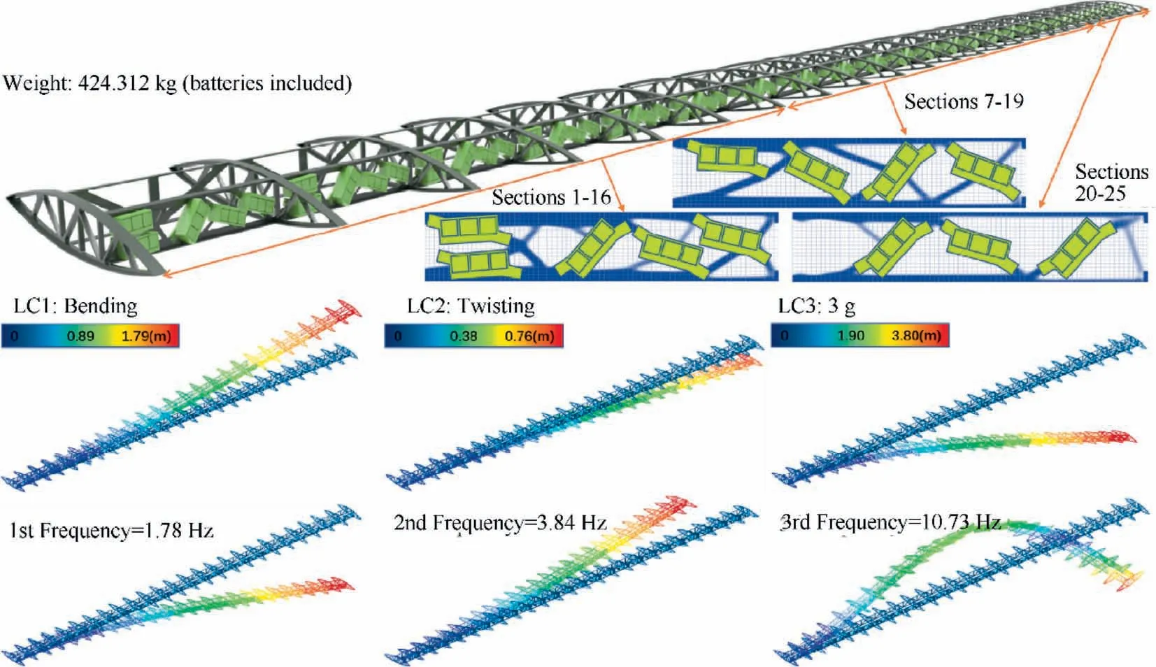
Fig. 9 Optimized designs of segmentally periodic design.

Table 1 Comparison of the optimized results.
This work shows a typical weight priority mode i.e.the initial design has reached the weight index according to the system requirements. If the designers believe that there is still space for weight saving, further detailed optimization with lightweight as the design objective and mechanical performance constraints can be implemented.
4. Conclusions
A solar-powered drone’s wing structure is designed and optimized in this paper. Layout of the batteries assembled in the wing is optimized together with the structural topology in an integrated optimization procedure. In the optimized design,the batteries become parts of the load-carrying structures.The mechanical performances are improved significantly in different optimized designs.
Considering the manufacturing and assembling requirements, the initial design of the wing beam used a periodic structure configuration in different wing sections, which prevents the performance optimization to a certain extent. In the integrated optimization,we consider a pure periodic design like the original design,a free optimization without periodicity and a segmentally periodic design as a compromise.
Compared with the initial design, the free optimization result has the best performance and the worst manufacturability.The pure periodic design has the least improvement in performance but the best convenience in manufacturing. Inspired form the batteries layout and material distribution in the free optimization, the segmentally periodic optimization balances the structural performance and manufacturing convenience.The final result suppresses the structural deformation by more than 22.8%,raises the first 3 natural frequencies by more than 16.6%.
Declaration of Competing Interest
The authors declare that they have no known competing financial interests or personal relationships that could have appeared to influence the work reported in this paper.
Acknowledgements
This work is supported by Key Project of Natural Science Foundation of China (Nos. 51790171, 51761145111,51735005).Natural Science Foundation of China for Excellent Young Scholars (No. 11722219).
 CHINESE JOURNAL OF AERONAUTICS2021年7期
- CHINESE JOURNAL OF AERONAUTICS的其它文章
- Polynomial networks based adaptive attitude tracking control for NSVs with input constraints and stochastic noises
- Morphing wing flaps for large civil aircraft:Evolution of a smart technology across the Clean Sky program
- Review on bio-inspired flight systems and bionic aerodynamics
- SARISTU:Adaptive Trailing Edge Device(ATED)design process review
- Continuous morphing trailing-edge wing concept based on multi-stable nanomaterial
- A hybrid multidimensional Riemann solver to couple self-similar method with MULTV method for complex flows
