Morphing wing flaps for large civil aircraft:Evolution of a smart technology across the Clean Sky program
Rosario PECORA
Department of Industrial Engineering, Aerospace Division, University of Naples ‘‘Federico II”, 80125 Napoli, Italy
KEYWORDS Electro-mechanical actuators(EMA);Green regional aircraft;Mechanical systems;Morphing flap;Morphing wing;Smart aircraft;Smart structures;Variable camber airfoil
Abstract Morphing wing structures are widely considered among the most promising technologies for the improvement of aerodynamic performances in large civil aircraft.The controlled adaptation of the wing shape to external operative conditions naturally enables the maximization of aircraft aerodynamic efficiency,with positive fallouts on the amount of fuel burned and pollutant emissions.The benefits brought by morphing wings at aircraft level are accompanied by the criticalities of the enabling technologies,mainly involving weight penalties,overconsumption of electrical power,and safety issues.The attempt to solve such criticalities passes through the development of novel design approaches, ensuring the consolidation of reliable structural solutions that are adequately mature for certification and in-flight operations. In this work, the development phases of a multimodal camber morphing wing flap, tailored for large civil aircraft applications, are outlined with specific reference to the activities addressed by the author in the framework of the Clean Sky program.The flap is morphed according to target shapes depending on aircraft flight conditions and defined to enhance high-lift performances during takeoff and landing, as well as wing aerodynamic efficiency during cruise. An innovative system based on finger-like robotic ribs driven by electromechanical actuators is proposed as morphing-enabling technology; the maturation process of the device is then traced from the proof of concept to the consolidation of a true-scale demonstrator for pre-flight ground validation tests. A step-by-step approach involving the design and testing of intermediate demonstrators is then carried out to show the compliance of the adaptive system with industrial standards and safety requirements. The technical issues encountered during the development of each intermediate demonstrator are critically analyzed, and justifications are provided for all the adopted engineering solutions. Finally, the layout of the true-scale demonstrator is presented, with emphasis on the architectural strengths, enabling the forthcoming validation in real operative conditions.
1. Introduction
The rapid growth of the air transport volume is currently posing relevant concerns in terms of associated environmental impacts and eco-sustainability;as the overall number of flights per year is expected to double in the upcoming decade, great research efforts are demanded for the development of new technologies addressing the greening of next-generation aviation.
Active from 2006, the Clean Sky Green Regional Aircraft(GRA) research program1,2aims to mature, validate, and demonstrate the green aeronautical technologies that best fit the European regional aircraft expected to fly from 2025 onwards; among these technologies, extensive scope is given to morphing and multifunctional wing architectures for highly efficient aerodynamics, as well as for load control and alleviation functionalities. With nearly 600 committed institutions across 24 countries, Clean Sky surely represents the largest European effort toward the consolidation of cutting-edge and highly competitive products specifically tailored to large civil aircraft applications.
In this challenging framework, a novel adaptive structure was conceived to enable the in-flight camber morphing of the wing flaps of a reference 100-seat aircraft.The driving motivation of the research was found in the convenience of replacing a conventional double-slotted flap with a single-slotted camber morphing flap, ensuring enhanced high-lift performances—in terms of maximum attainable lift coefficient and stall angle—at reduced flap deployment angles;at the same time,load control functionalities needed to be enabled in cruise by properly cambering the flap portion that was still exposed to the aerodynamic flow when the flap was retracted into the wing.
Thanks to flap adaptivity,the aerodynamic efficiency of the reference aircraft resulted in a 5%increase compared with the case of a conventional wing, with an equivalent reduction of fuel burned per flight and pollutant emissions.3Apart from the lower environmental impact, lower consumption of fuel would have meant lower operative costs, and therefore,remarkable profits for an average size fleet of commercial aircraft.4,5This is fully in line with the indubitable point that the true potential of morphing lifting surfaces is essentially associated with their practical application to large civil airplanes,since it is for this category of vehicles that the largest benefits are expected to be introduced.6–9However, as the size of the aircraft increases, it becomes increasingly difficult to design adaptive structures that are flexible enough to enable wing shape morphing, and simultaneously, stiff enough to safely withstand the significant flight loads arising in service.
The current literature is rich with examples of wing morphing concepts tailored for small (generally) unmanned aircraft,10each one dealing with the adaptation of a specific geometrical characteristic—from the airfoil camber11,12to the span or chord length13and from the surface area14to the twist or dihedral angle.15Nevertheless, few credible concepts tailored to commercial aircraft applications have been explored up to the point of experimental validation. Among the solutions that do exist, the morphing leading and trailing edges developed in the framework of the SARISTU project16–21and the adaptive compliant trailing edge designed by Flexsys®22are the sole devices that deserve to be mentioned in force of the technological maturity they proved to possess.
The architecture of the morphing flap developed within the Clean Sky program can be considered an evolution of SARISTU trailing edge architecture,23,24and it is characterized by augmented functionalities, improved system performances,and superior readiness for flight and certification. Respecting the Flexsys® solution, the adaptive flap shows two main elements of novelty. First, the flap functionality is preserved and enhanced through camber morphing capabilities, while the flap is totally removed from the wing and the lift control is obtained by largely cambering the wing trailing edge according to Flexsys®.
The Clean Sky approach clearly brings higher reliability to the developed device; as in the case of morphing functionality loss, the flap continues to work as a conventional system with no relevant effects on aircraft operations and flight safety.Furthermore, contrary to what was proposed by Flexsys®, the flap camber variation was obtained by smart mechanisms embedded into the primary structure and no structural elements need to be bent to enable the shape morphing; this clearly represents a great advantage in terms of overall system robustness and fatigue life.
At present, the Clean Sky adaptive flap can be considered the most innovative and advanced morphing system of industrial relevance, characterized by well-proven and recognized levels of reliability, robustness, and technological readiness for massive implementation on future aircraft. In this work,the 10-year-long research path leading to the maturation of such a challenging technology is presented.
Although carried out in the framework of the Clean Sky program, the entire research duly considered experiences resulting from parallel projects, where similar technologies were addressed under the technical direction of the author and his research group. Some of these experiences, and the related lessons learned,have been properly highlighted to provide a more comprehensive justification of the design strategies, architectural solutions, and validation methodologies adopted for the consolidation of a truly revolutionary smart architecture.
2. Preliminary architectural layout and proof of concept
At the beginning of the Clean Sky program, the improvement of high-lift performances was considered a paramount task for the development of an innovative regional aircraft characterized by unequaled efficiency and reduced environmental impact, both in terms of fuel burned and noise emissions. A common reference platform represented by an innovative 100-seat turboprop aircraft configuration was chosen for the investigation of the enabling technologies, including smart morphing architectures. The wing flap was among the first domains of investigation, and great efforts were made to improve flap efficiency by working on the definition of suitable aerodynamic shapes, as well as on advanced deployment systems for optimized flap settings during takeoff and landing.
In the framework of these investigations, great attention was paid to the adoption of morphing structures for the active control of flap camber during flight. It was indeed proved, by means of computational fluid dynamic analyses,3,25–28that by actively controlling the camber of the flap, significant aerodynamic advantages could have been achieved in terms of wing CLmaxand stall angle increase, even with small deployment angles of the flap. As a consequence of this, a conventional double-slotted flap could have been replaced by an equally(or more) efficient single-slotted flap with camber morphing capabilities; in addition, the complex deployment systems typically required by a double-slotted flap could have been conveniently replaced by a simpler flap track, assuring a limited number of settings, as the hyper-lift functionality was mainly obtained by actively controlling the flap camber.
A preliminary investigation was then carried out to demonstrate the practical feasibility of a structural system enabling flap camber morphing according to reference optimized flap shapes, and in compliance with industrial quality standards and challenging requirements in terms of limit design loads.To limit the project risks(and the budget)associated with this task,the feasibility demonstration was referred to a portion of the flap delimited by two cutting planes normal to the flap leading edge and 0.8 m distant from each other along the flap span.The flap segment selected as investigation domain for the design and validation of the morphing architecture3was characterized by the real flap chord (0.62 m) and maximum thickness (0.18 m), as well as a span of 0.8 m;thanks to the limited spanwise size, the flap tapering was neglected, reducing the complexity of a three-dimensional aero-structural design to a bidimensional problem.
To enable the controlled morphing of the flap camber, a finger-like mechanism was conceived for the flap ribs. Each rib (Fig. 13,27) was designed as a system of four plates (B0,B1, B2, B3) consecutively interconnected by hinges placed along the airfoil mean line(A,B,C).Two additional links were included to further connect not adjacent rib plates, namely,plate B0 to plate B2 (link L1) and plate B1 to plate B3 (link L2). Thanks to these links, each rib resulted in a 1-degree-offreedom mechanism;for instance,by rotating the second plate in relation to the first one, all the remaining plates rotate in relation to each other according to specific gear ratios, which are functions of the links positions. The position of the additional link represented a design variable and was properly set to ensure the compliance of the plates’ motion with the target morphed shapes to be implemented for the flap rib.
The active degree of freedom of each rib mechanism was controlled by a rotary electromechanical actuator which had the two following functions: to activate the rib mechanism for shape morphing and to lock the mechanism to safely withstand the external loads.The adoption of a mechanical amplification system for the actuation torque was considered mandatory to accomplish the above-mentioned functions while minimizing the size of the actuators and the electrical power demand. Referring to the picture shown in the top-left corner of Fig. 1, for each rib, the actuation torque was transferred to a gear box installed on the rib plate B0 which converted the rotation induced by the actuator shaft into the sliding of a cursor along the chord of the flap; thanks to a leverage system composed by two interconnected forkshaped beams, the sliding of the cursor was used to deflect the rib plate B2, and consequently, to control the motion of all the remaining plates. A careful design of the gearbox and leverage system3allowed for the adoption of small stepper motors,requiring nearly 24 W for the actuation of the flap segment under limit design loads (70 kg).
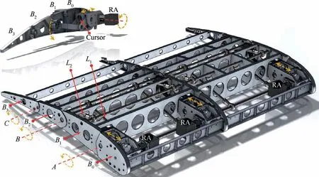
Fig. 1 Morphing flap: layout of demonstrator for proof of concept.3,27
The actuated rib arrangement described so far was replicated three times along the span of the flap segment,and stiffening elements (spars and stringers) were used to connect the homologue plates of the adjacent ribs(Fig.1).Light aluminum alloys were selected for all the structural components, and a physical prototype was manufactured to prove the feasibility and reliability of the conceived architectural concept. Two types of tests were addressed as follows:
- Functionality tests to show that the device was able to morph into the target aerodynamic shapes,in a controllable and replicable manner; and
- Static tests to demonstrate the elastic behavior of the device under the action of the limit design loads.
To prove the functionality of the device,flap morphing was activated, and the entire shape transition was recorded with a high-resolution camera(Fig.2).Pictures of the morphing process were taken,and a perfect match was obtained between the realized section shapes (Fig. 2(b), (c)) and the target reference ones.3Limit design pressures were simulated by means of a sandbag placed on the lower side of the flap prototype surface(Fig. 3(b)). No permanent deformations were detected by strain gauges located in the most stressed region of the device;after the removal of the sandbags, the elastic deflection of the flap (nearly equal to 7 cm) was fully recovered3(Fig. 3(c)).
The recovery of the initial undeformed shape(Fig.3(a))was also made possible during the loading phase by activating the morphing function to properly adjust the shape of the camber line.Although the test campaign produced good results for the success of the proof of concept, the stiffness of the prototype was judged too low for safe in-flight operations,and was therefore reported as a key issue to be addressed during the advanced design phase of the device.
3. New functionalities and advanced architectural layout
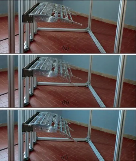
Fig. 2 Morphing flap proof of concept: Functionality test.
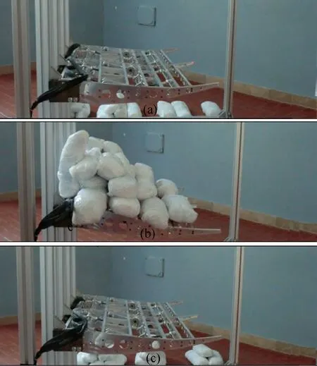
Fig. 3 Morphing flap proof of concept: Static test.
As it had been proven that flap camber morphing could be enabled by a smart architecture characterized by a good similarity with standard aeronautical devices, and therefore, with good potential for certification, a more challenging phase started for the overall technology demonstration. In this phase,23the investigation domain to be considered for the advanced design of the technological demonstrator was enlarged to half of the outer flap segment of the reference aircraft(Fig.423).The size of the flap portion to be morphed had a span(b)of 3.60 m,root chord(cr)of 1.20 m,tip chord(ct)of 0.9 m, and maximum thickness equal to 0.24 m. The bidimensional simplification adopted for the proof of concept was no longer applicable due to the tapering of the flap, and a more complex and significant set of loads had to be considered to properly size the components of the smart architecture.
In addition, a new functionality requirement was placed,where the flap should have implemented two different morphing modes depending on the specific flight condition. These modes were as follows:
- Morphing mode 1: Overall camber morphing (as in the proof of concept)to enhance aircraft high-lift performances during takeoff and landing (flap deployed); and
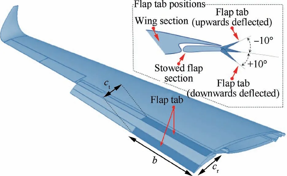
Fig. 4 Advanced design of the morphing flap demonstrator:investigation domain and tab deflections.23
- Morphing mode 2: Tab-like morphing comprising upwards/downwards rotation of the flap tab in the range[-10°,+10]. The tab is the segment of the flap that is still exposed to the aerodynamic flow when the flap is stowed(dark colored flap portion in Fig. 4). Thanks to this additional morphing mode, wing load control functionality is enabled to maximize the wing aerodynamic efficiency during cruising.
The bimodal morphing requirement demanded a radical change in the finger-like rib architecture defined for the proof of concept as a single-degree mechanical system could not allow for two independent motions of the rib.
The actuation strategy developed for the proof of concept was preserved to enable the overall camber morphing during the takeoff and landing phases. The rib was always characterized by four consecutive segments(B0,B1,B2,B3)hinged along the camber line at the positions marked by points A,B,and C in Fig. 5.23As in the proof of concept, blocks B0and B2were further connected through a link,denoted by L in Fig.5,which made B0,B1,and B2move as a single degree-of-freedom mechanism.The last block,B3,was connected to block B2only,and no further link was introduced to slave its rotation to the motion of the other blocks.
Two rotary electromechanical actuators (A1, A2; Fig. 5)were adopted to morph the rib; the first actuator (A1) controlled the motion of the first three blocks, while the second(A2) controlled the rotation of the last block around hinge C. The torque of each actuator was duly amplified by optimized mechanisms (M1, M2; Fig. 5) playing the same role as the gearboxes used in the proof of concept. According to the geometrical characteristics of the constitutive components,the amplification factor(mechanical advantage)of each mechanism reached the maximum value of 3 along the entire shapemorphing process. In morphing mode 2, the amplification mechanism M1was locked and actuator A1powered off;actuator A2was activated,and the torque amplification mechanism M2induced the upwards/downwards deflection of the flap tab(i.e.,block B3).During morphing mode 1,both actuators were simultaneously activated; the torque of actuator A1was used to move amplification mechanism M1, which in turn, made block B2rotate in relation to hinge B; as B0, B1, and B2comprise a single degree-of-freedom mechanism(due to link L),the rotation of B2around B implied the rotation of B1around A according to specific gear ratios depending on the position of the link L, and ultimately, on the target morphed shapes to be realized. To realize those shapes, actuator A2was synchronized to actuator A1, controlling the deflection of the flap tip according to the positions assumed by blocks B0, B1, and B3.
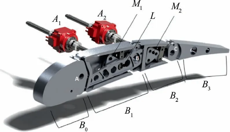
Fig. 5 Bimodal morphing rib mechanisms.23
Apart from the macroscopic difference represented by the double actuation line, the bimodal morphing rib was characterized by a more compact and robust layout than that conceived for the proof of concept. The rib blocks were thickened along the flap span direction to properly host all the amplification mechanisms and leverages required to morph the architecture. This design choice led to significant improvements in the assembly phase of the flap device, as no interference occurred between the longitudinal stiffening elements and the components of the actuation transmission. In contrast,elastic deflections of the rib under external loads were dramatically reduced thanks to a more rational design of link L,which was placed closer to the rib central plane to avoid undesired bending effects at its supports and shaped to increase the overall stiffness of the rib architecture.
As in the proof of concept, segmented spars and stringers were adopted to realize a multi-box arrangement, elastically stable under bending and torsion; the multi-box architecture was characterized by seven bays, each delimited by a smart rib(Fig. 623). The chordwise length of the first and last blocks of each rib was reduced along the span to properly fit the tapered planform of the flap; the chord of the central blocks hosting all the mechanisms for rib morphing (blocks B1and B2;Fig.5)was instead kept constant,allowing for a more efficient installation of the actuators’ transmission line.
Four actuation groups were placed in the first, third, fifth,and seventh bays of the flap; each group was composed of two actuators driving the shape morphing of the ribs delimiting the bay.The actuator type(see Table 1)was selected based on tradeoff studies aiming at finding the best solution in terms of provided torque versus power demand,overall volume,and weight.
Eight controllers (LTi® Servo One Junior29) were installed in the first four bays of the leading edge to drive the actuators.Encoders for relative rotation measurement were placed around hinges A,B,and C(Fig.5)of the first,fourth,and last ribs along the span;their output was used in feedback to drive the actuators during morphing,as well as to preserve the commanded flap shape in case of undesired changes induced by external perturbations (including excessive elastic deformations due to the aerodynamic pressure).
All the structural components of the advanced demonstrator were realized in light aluminum alloy, mainly referring to high precision numerical control machining processes. Both ribs and longitudinal stiffening components were properly shaped to enable the installation of a segmented skin solution characterized(on both the upper and lower sides)by four large panels sliding on each other like armadillo shells (Fig. 7(a)23).Silicon rubber seals23were introduced to prevent airflow leakages in flight and reduce the friction between adjacent skin panels.Advanced multi-body simulations of the flap morphing kinematic were launched to properly define the shape of the seals, as well as to check for the absence of clashes between adjacent subcomponents in relative motion.
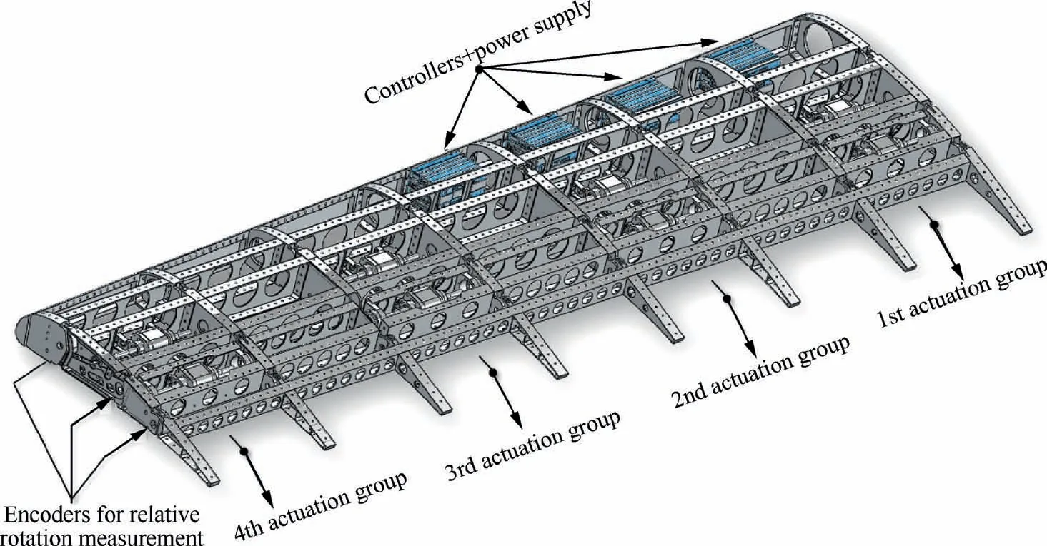
Fig. 6 Morphing flap, layout of advanced technological demonstrator.23

Table 1 Main characteristics of selected actuator.
The adoption of a segmented skin solution was influenced by the experiences gained in two relevant research projects running in parallel with Clean Sky—the CRIAQ-MDO50530–33and SARISTU.19,23In these projects, the same design team involved in the advanced demonstration of the morphing flap was responsible for the structural design and validation of two innovative morphing devices tailored for large civil aircraft application—a morphing camber aileron34–38(CRIAQMDO505) and an adaptive wing trailing edge39–43(SARISTU). While, for the morphing aileron, a segmented skin solution was considered, the morphing trailing edge was equipped with a compliant skin architecture made of stretchable panels. In more detail, the change of shape induced by morphing was accommodated by the sliding of adjacent skin panels for the aileron and by the elastic deformation (extension/compression) of the upper and lower skin panels for the wing trailing edge. The deformation of the skin panels was enabled by a smart multi-material system made of stiff metallic shells joined to soft foam strips in an accordion-like arrangement;the metallic shells were incorporated to assure adequate bending and shear stiffness to withstand aerodynamic pressure, while the foam strips accommodated the relevant deformations induced by the cambering of the trailing edge.44,45A layer made of hyper-elastic silicon-based polymer was glued onto the metallic shells and foam strips to ensure adequate protection from environmental factors.
Each skin arrangement had advantages and disadvantages.The compliant skin solution ensured clean and smooth aerodynamic surfaces, while the adoption of skin segments led to small steps and discontinuities with degradation of aerodynamic performances due to premature flow separation.In contrast, from the manufacturing, assembly, and maintenance standpoints,the segmented skin solution resulted in more convenience due to its greater simplicity, strength against debris impacts,and ease of repair in case of damage.Therefore,looking at the implications for aircraft operations, the segmented skin solution was preferable,while the compliant skin solution represented the optimal candidate to enhance the aerodynamic performance of the overall architecture. Thanks to the extensive wind tunnel campaigns carried out during both projects,it was possible to collect a wide set of results and make some extrapolations to the morphing flap to properly select which skin arrangement would be more suitable.
Due to the high incidence angles at which the flap had to work, it was observed that the presence of small gaps along the upper/lower skin would not significantly alter the aerodynamic performances of the device; in more detail, the maximum high-lift coefficient of the wing with continuous flap skin was estimated to be only 0.2% higher than that obtained in the case of segmented skin. This figure was judged as an acceptable performance loss, fully compensated for by the large operative advantages associated with the segmented skin solution. In addition, power consumption issues were duly taken into account, and they played a decisive role in the choice of the segmented skin as the optimal cover solution for the flap architecture:Nearly 35%of the available actuation power was required to deform the compliant skin according to the target morphed shapes of the flap; conversely, the motion of the segmented skin occurred without any demand for additional power respectto that needed to morph the underlying structure. Following the same approach as for the proof of concept, the advanced demonstrator was also subjected to functionality and static tests, although more accurate and sophisticated experimental protocols were implemented,building on the experiences gained during CRIAQ-MDO505 and SARISTU projects.
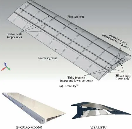
Fig. 7 Skin arrangements for adaptive camber surfaces.
4.Functionality test of the advanced technological demonstrator
Functionality tests were carried out to demonstrate that the flap could reproduce target morphed shapes in a controlled and repeatable manner. The target morphed shapes were considered successfully fitted if the angles between adjacent rib blocks—obtained upon actuator activation—matched the design values pertinent to each morphing mode(Table 2)with a precision of 0.5°. The first and the last ribs of the flap were equipped with additional high precision encoders measuring the relative rotations between blocks B0and B1and blocks B2and B3; it was considered irrelevant to place an additional encoder between B1and B2, since B0, B1, and B2had a single degree-of-freedom as a result of the cross-link L (Fig. 5).The encoders were equipped with digital displays for realtime reading of the measured rotations. The flap was then installed on an exhibition support and secured to an external safety rig (Fig. 8 (a)); the test protocols outlined in Table 3 were followed.46
Test protocols 1 and 2 were repeated 20 times, and at each cycle (Fig. 8 (b)), the measured angles were fully compliant with the design targets at both the inner and outer flap sections(Fig. 9). Moreover, the recordings related to the encoders at the flap root and tip sections (Fig. 9) matched perfectly, proving the successful implementation of morphing mechanics along the flap span (absence of undesired morphing-induced twist or shape alteration along the span).

Table 2 Design values for relative rotations between adjacent rib blocks.
5. Static test of the advanced technological demonstrator
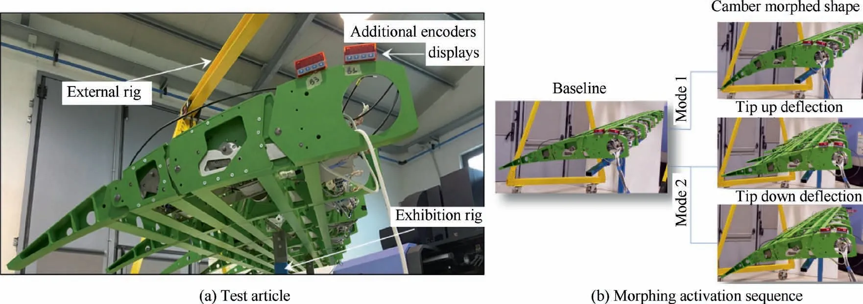
Fig. 8 Functionality test of morphing f lap: test article and morphing activation sequence.
The static test was carried out to demonstrate the flap’s capability of withstanding limit loads expected in service without permanent deformations, failures or buckling. Due to the relevance of the total load to be app lied(1.5 tons26,46),numerical analyses were prelim inarily carried out to virtually simulate the test;analysis outcomes were used to accomp lish the following:

Table 3 Functionality test protocols.
- Safely address the experimental cam paign, being prepared to detect (potentially dangerous) deviations between the actual and the expected structural behavior of the device;
- Properly individuate the most stressed regions of the prototype for a rational installation of the deformation sensors;and
- Verify the adequacy of the test rig and whiff le tree used to app ly the loads.
Relying on the result of the pre-test analyses, the sensor expected to record the maximum strain (maximum strain sensor, M SS) was located on the mechanical link (marked w ith L in Fig. 5) between blocks B0and B2of the second rib. To demonstrate the recovery of the full elastic def lection, Linear Variable Differential Transducers (LVDT) were installed to measure the disp lacement at the f lap tip. The sensor expected to record the maximum def lection(maximum def lection sensor,M DS) was that located at the tip of the second rib. In Fig. 10(a), the test setup is outlined w ith indications on the M SS and MDS positions, the main elements of the load transm ission system, and the clamping plates adopted to constrain the f lap in correspondence of the joints to the dep loyment tracks.
As a f inal stage, the test protocol of Table 4 was implemented. Load steps of 100 kg, w ith a loading speed of 10 kg/s, were considered adequate to avoid any dynam ic amp lif ication. A pause of 10 s at the achievement of each load step was set to check the acquired data; load levels were measured through a load cell installed between the hydraulic jack and the whiff le tree (Fig. 10(a)).
No failures occurred during the tests. The app lied load value and MDS/M SS recorded data are plotted against time in Fig. 10(b). The maximum recorded deformation and disp lacement were in good agreement w ith numerical expectations, and the full recovery of elastic deformations/def lections occurred once the test article was unloaded.
By using the potentiometers embedded in each of the controllers installed in the lead edge, it was possible to measure the power absorption of each actuator during the loading phase.A t the lim it load condition,the overall power adsorbed by the actuation system was equal to 350 W, w ith the greatest amount consumed by the f irst actuator located in the third bay(16%, Fig. 11). This occurrence was perfectly in line w ith the point that, under lim it load conditions, the torque induced by the whiff le three reached a peak corresponding to at the third rib, demanding more effort from the actuators located in the third bay. The overall power consum ption of 350 W was well below the saturation value of the entire actuation system (650 W=8×81.25, see Table 1); this practically demonstrated the goodness and robustness of the im p lemented design as a relevant amount of actuation torque could still be delivered to control the f lap shape under lim it design load conditions.
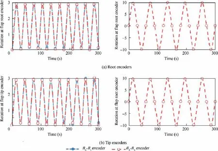
Fig. 9 Functionality test of the morphing flap: measured rotations at flap root/tip encoders (first 10 cycles, morphing modes 1 and 2).
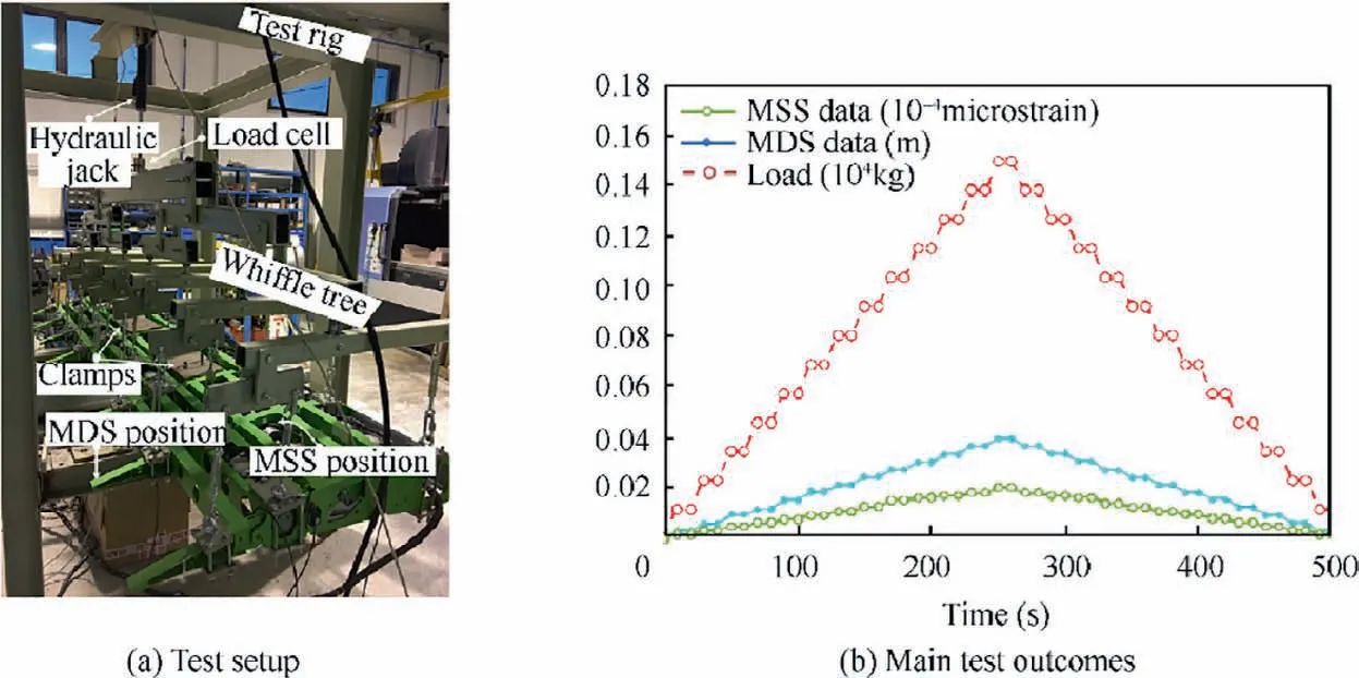
Fig. 10 Static test of morphing flap.
6.Toward the full technological demonstration of a multi-modal camber morphing flap
The advanced demonstration represented a relevant milestone in the maturation process of the addressed technology; the promising results of the experimental campaigns, in combination with the increasing appeal of the proposed architecture for an effective installation on large aircraft,paved the way to further research activities oriented to a more comprehensive assessment of the morphing flap from the perspective of inflight tests and operations.The assessment was thought necessary to overcome the limitations of the advanced demonstration while further improving the architecture of the device in the direction of a ready-to-fly industrial product.
First, the entire outer flap segment of the reference wing should have been addressed to properly face design, production,and testing issues at the integral component level.Second,important changes to the already consolidated architecture should have been made to increase the industrial interest on the smart system; ways for improvements were essentially found in the exploration of the following topics:
- Reduction of installed power thanks to the adoption of a lower number of actuators;
- Minimization of spare parts and simplification of the assembly process;
- Overall weight reduction; and
- Minimization of the operational risks in case of actuation system failures.
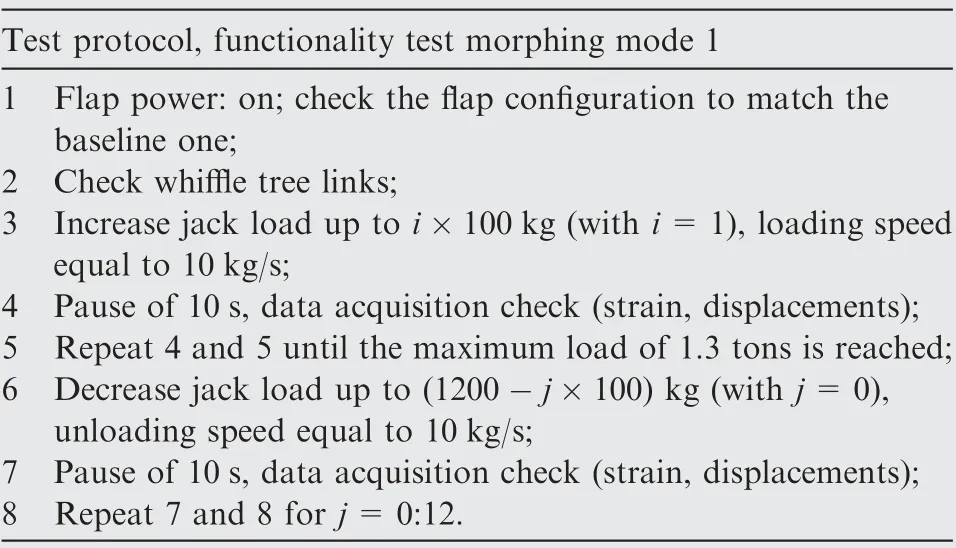
Table 4 Static test protocol.
The Airgreen2 project, which is still running in the framework of the second phase of the Clean Sky program(CleanSky2-REG IADP2,47), represented the first opportunity to optimize the morphing flap system by addressing all the above-mentioned issues.
Here,an overview of the flap layout resulting from the Airgreen2 project is presented; the device is currently at the executive design stage and is expected to be produced and tested in the next couple of years. Starting from the general layout of the advanced technological demonstrator,design changes were first introduced to enhance the robustness and efficiency of ribs’mechanisms and reduce the number of required actuators.The smart function of the ribs,namely their capability to drive morphing as an inner movable articulation of the flap structure, was preserved; the ribs’ architecture and the associated mechanics were modified to improve the reliability and efficiency of morphing through a more compact and robust design. The generic rib was composed of four consecutive and entirely redesigned blocks (B1, B2, B3, B4; Fig. 12) connected by three frictionless hinges (A, B, C) located along the airfoil camber line.
Blocks are allowed to rotate in relation to each other,making the airfoil camber line morph. Blocks B1and B3are interconnected by means of a suitably shaped beam (L) with two hinges at the edges; an internal leverage (M1) is hosted by block B2and interconnects blocks B2and B4. This leverage is activated by an external rotary actuator acting along the shaft (A1) and amplifies the actuator’s torque.
The rotation induced around A1makes the leverage M1move, and therefore, changes the relative position of block B2in relation to block B4; at the same time, blocks B1and B3are forced to follow the movement because they are mutually interconnected with the remaining blocks.The position of the link L and the pivots of leverage M1were selected in such a way that, upon the rotation of shaft A1, all the rib blocks rotate around hinges A,B,C according to specific angles compliant with the external morphed shapes to be achieved.A secondary leverage (M2) links B4(flap tip) to B3and is driven by the rotation of the actuator acting around the shaft A2. The secondary leverage, hosted by block B3, amplifies the torque around A2and makes B4rotate around hinge C,implementing the tab-like morphing. During morphing mode 1,48,49the secondary leverage is fixed since only shaft A1is activated.In contrast, shaft A1is locked during morphing mode 2.48,49
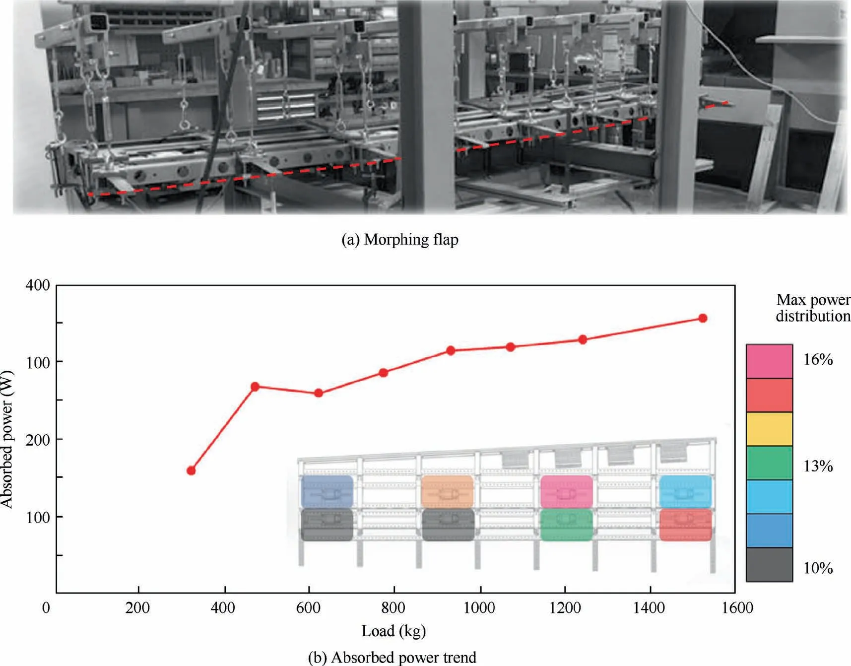
Fig. 11 Static (limit) deflection of the morphing flap and absorbed power trend.
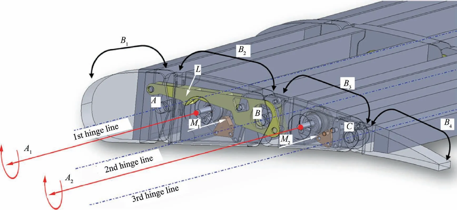
Fig. 12 Smart rib mechanisms (Airgreen2 improved layout48).
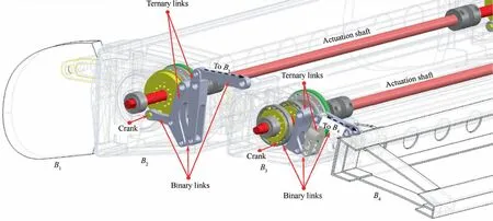
Fig. 13 Detail of actuation torque amplification mechanisms (Airgreen2 improved layout48).
Leverages M1and M2were optimized to increase the mechanical advantage provided by the inner mechanisms of the advanced demonstrator rib.The optimization process consisted of parametric kinematic analyses defining the leverage components’ number, shape, and position as functions of the mechanical advantage to be implemented by the overall mechanism.48At the end of the process,the most convenient layout for each leverage was characterized by six components, comprising a crank, two ternary links, and three binary links,arranged as reported in Fig. 13. All the items were connected by cylindrical hinges; the crank and ternary links were doubly supported on rib-block plates to avoid out-of-plane rotations during the kinematic evolution of the inner mechanisms. The input actuation torque at the crank was used to start the motion of the chain of links;the last link of the chain was connected to the rib block to be rotated(B3for mechanism M1,B4for mechanism M2)and generated the output torque,enabling the rotation of the rib block about its hinge axis.The mechanical advantage (output torque/input torque) ultimately depended on links relative rotation centers,48and their positions were properly tailored to ensure high actuation authority.In Fig.14,the rotation of the actuated rib blocks(θB3,θB4)and the mechanical advantage of mechanisms M1/M2are plotted as functions of the crank rotations. For mechanism M1, the minimum mechanical advantage was equal to 6;as θB3became greater than 13°, the mechanical advantages rapidly increased in line with the demand for higher torque to properly counteract the external aerodynamic loads generated by the augmented camber of the flap. Similarly, for mechanism M2, the mechanical advantage was equal to its minimum value(nearly 5) when the flap tab (rib block B4) was in neutral position; as the tab was deflected upwards(-10°≤θB4<0°)or downwards(0°<θB4≤10°), the mechanical advantage rapidly increased,providing adequate actuation authority against the aerodynamic loads induced by tab rotation.
A multi-box arrangement was considered to transfer the morphing capabilities of the ribs to the overall flap structure.Each box was characterized by a single-cell configuration delimited by homologous blocks of consecutive ribs along the span and by spars along the chord. Thanks to the greater morphing authority of the ribs, their pitch was set equal to 580 mm (Fig. 15), leading to two ribs less than those that would have been required if the pitch of the advanced demonstrator had been used.In addition,the spars were set to be continuous along the span of the flap and no longer segmented by the ribs, as happened for the advanced demonstrator; this led to a more robust structural arrangement in bending as well as to a reduced number of spare parts.
A through-shaft solution was selected to enable the actuation of three rib blocks with a single motor (R1, R2; Fig. 16).The segmentation of the shaft along the span was obtained through elastic joints,ensuring the correct torque transmission in the presence of high bending-induced deformations. Harmonic Drive® (HD) gear reducers (in green in Fig. 16) were installed to amplify the torque supplied by the motors. The HD model CPL-17-2A48was selected based on its overall volume and performance.
When the brushless motor is on, the main shaft transfers the rotational speed to the HD gearbox installed on each rib-block plate.Following the action of the HD,the rotational speed of the shaft is reduced, and the torque is amplified to nearly 200 times the nominal value.
The crank of each leverage (M1and M2in Fig. 12) is directly connected to the low-speed (high-torque) shaft that comes out of the HD device. The kinematic chains of each rib are then activated, and the full morphing system changes its shape.
Thanks to the rational sizing of the transmission lines,only six motors were required to morph the full-scale prototype(Fig. 15); even if larger than the advanced demonstrator, the prototype required fewer actuators,which were in turn characterized by reduced dimensions and weight (Table 5).
The segmentation of the rear transmission line in three different portions,covering bays 1 and 2,bays 4 and 5,and bays 7 and 8,allowed for an equivalent segmentation of the flap trailing edge into three different tabs with independent actuation In case of synchronous actuation of the tabs, morphing mode 2 would have been implemented; by properly distributing the actuator rotation along the three transmission lines,it was possible to achieve a third morphing mode characterized by differential deflections of the tabs, in this way, implementing new shapes for the flap trailing edge for enhanced load control functionalities in cruise. This additional functionality marked the transition from a bimodal camber morphing flap to a more sophisticated architecture with multimodal morphing capabilities.To minimize the operational risk of the conceived layout,careful attention was paid to the behavior of the actuation system in the case of in-flight power shutdown. As for the advanced demonstrator, for the improved flap architecture,the torque provided by the actuators was also necessary to keep the flap structure in equilibrium under the action of external loads. In the case of power shutdown, no relevant torque would have been delivered by the actuators, and the entire structure would have collapsed well below the design limit load.
To solve this important safety issue, permanent magnetic brakes of the PMB® series 10050were mounted on the shaft of each actuator. The working principle of the brakes is drafted in Fig. 17.
With current off to the electric coil, the permanent magnet provided ongoing magnetic flux to engage the armature plate with the brake’s inner and outer friction faces. The load attached to the hub armature plate was held without power consumption. When the current was applied to the coil, the permanent magnet flux path was counteracted, reducing the magnetic force at the friction face contact points to zero. This allowed the diaphragm spring to pull the armature plate away from the magnet case, such that the load could rotate freely only while the power was applied to the coil.50
The adoption of such devices implied a significant change in the operations of the flap; the need for electrical current was indeed limited only to the flight phases in which morphing modes had to be activated. Whereas no morphing had to be implemented,the brakes in power off mode were used to maintain the flap shape, counteracting the external loads without the support of extra torque coming from the actuation system.
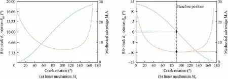
Fig. 14 M1 and M2: Mechanical advantages versus crank rotation (Airgreen2 improved layout48).
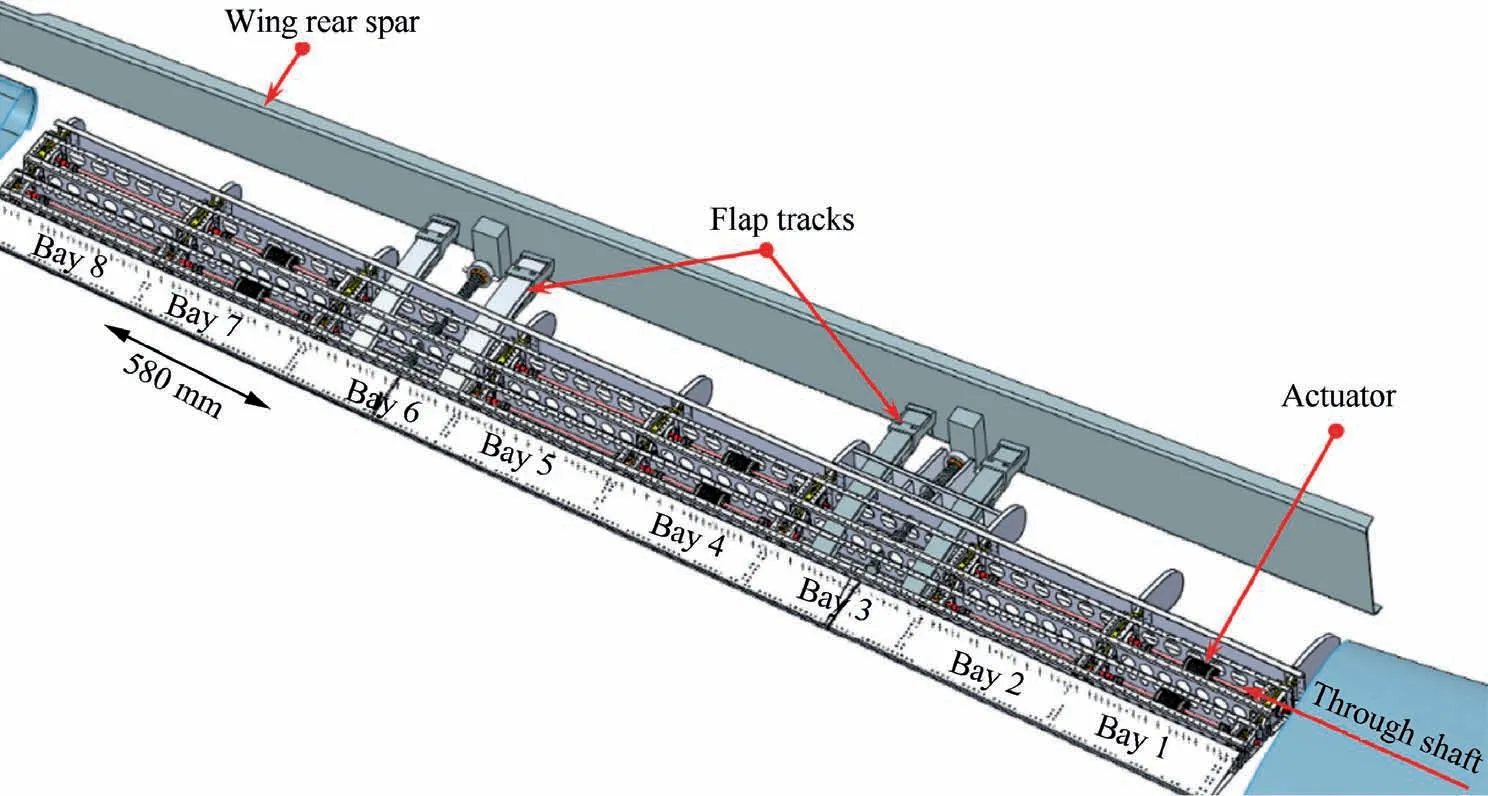
Fig. 15 Morphing flap arrangement (Airgreen2 improved layout).

Fig. 16 Through shaft transmission lines (Airgreen2 improved layout48,49).
Apart from the crucial contribution to the safety of flight in the case of electrical system failures,the adoption of brakes led to relevant power savings for normal operations, which summed up to those obtained through the enhancement of the actuation system authority and ribs mechanics efficiency.The obtained power savings combined with the significant reduction of system weight and complexity (/number of parts)resulting from the rational rearrangement of the load-carrying structure were considered more than adequate to successfullyconclude the design activities of the prototype for the full demonstration of multimodal morphing flap technology.
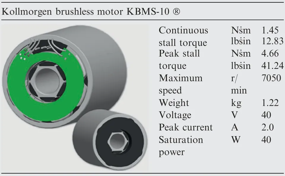
Table 5 Main characteristics of actuator selected for full-scale demonstrator.50
7. Conclusions
Active from 2006, the Clean Sky GRA program aims to mature,validate,and demonstrate the green aeronautical technologies best fitting the European regional aircraft that will fly from 2025 onwards; among these technologies, large room is given to morphing and multifunctional wing architectures for highly efficient aerodynamics, as well as load control and alleviation functionalities. In this challenging framework, a novel adaptive structure was conceived to enable the in-flight camber morphing of the wing flaps of a reference 100-seat aircraft;the driving motivation of the research was found in the convenience of replacing a conventional double-slotted flap with a single-slotted camber flap, ensuring enhanced high-lift and cruise performances through multimodal camber morphing capabilities.

Fig. 17 Permanent magnetic brake functions.
To comply with tight industrial requirements, the adaptive structure of the flap was rationally designed as a smart arrangement of conventional mechanical systems characterized by metallic components in relative motion. This design choice was made in full contrast to the widespread scientific opinion that morphing had to be conveniently implemented by means of imposed elastic deformations of flexible structural components,integrating smart materials like shape memory alloys or polymers.The adoption of controlled deformation(compliant)structures was deemed inadequate for the specific end application. To modify the flap shape, cyclic deformations of the structure would have been necessary under the action of the significant aerodynamic loads typical of a CS-25 category aircraft; a short fatigue life of the morphing flap was then expected,with prohibitive impacts on reference aircraft operations and maintenance plans. Smart materials with superelastic properties, although considered very efficient for overcoming fatigue issues, would have dwarfed the maturity of the overall system and its readiness for certification due to the lack of industrial production standards and consequent uncertainties on design allowables.Conversely,the mechanical solution based on metallic robotic ribs driving the shape adaptation of the flap proved highly promising in light of the small impacts on consolidated industrial manufacturing processes,aircraft operations, and compliance with airworthiness requirements. Similar considerations applied to the flap skin arrangement, where light metallic alloys and a modular segmented layout, replicating the multi-block segmentation of the finger-like ribs, were preferred to a compliant solution accommodating morphing-induced displacements through the deformation of super-elastic elements. Practically, the finger-like rib concept led to the definition of a multi-box structural arrangement where each box was covered by a skin segment. Flap shape adaptivity was basically implemented by replacing the conventional mono-cell structure with a complex mechanism characterized by active degrees of freedom; under these circumstances, the actuation system becomes a crucial component of the adaptive structure, working to suppress and control the active degrees of freedom. Therefore, an integrated design process was followed to define actuators, actuation transmission lines, and components of the adaptive structure,thus properly accounting for their mutual influence.Starting from the conceptual definition of the overall morphing system, the design process was rationally supported by experimental validation; at each design stage, technology demonstrators were manufactured and tested to down select the most promising arrangements to be further refined in the next design phase. In this way, the morphing flap technology experienced a gradual and well-sustained maturation process up to the consolidation of a full-scale prototype for final functionality tests in real operative conditions.
Starting from highly mature technological solutions, effective from the functionality and robustness standpoints, new research lines are envisaged to further enhance the morphing flap with reference to the broader spectrum of requirements posed by a cost-effective and sustainable integration at the aircraft level. Therefore, a rational re-engineering of the flap’s constitutive elements is expected to be addressed to bridge the gap between a reliable integrated smart system and an affordable, cost-competitive aeronautical component. Along this process, advanced research lines will be activated and mainly oriented to the following:
• Reducing the weight of the system by switching to hybrid solutions prevalently based on advanced/recyclable composite materials;
• Reducing the mechanical complexity of the system by decreasing the number of constitutive parts; along this direction, the convenience of additive manufacturing to replace entire sub-assemblies with integral components that are geometrically challenging for conventional manufacturing processes like forging and milling will be explored;
• Simplifying the device manufacturing and assembly through the adoption of rational design solutions for fast series production (increase of components commonality,simplifications of joining mechanisms and sequence);
• Reducing the effects of the device on aircraft maintenance and repair procedures by facilitating the visual inspection of the inner components and embedded electromechanical systems; and
• Reducing the effects of the device on aircraft maintenance and repair procedures via the integration of a smart health monitoring system checking for the integrity of the structural components and operativity of all installed equipment related to actuation, shape sensing, and shape control.
Declaration of Competing Interest
The authors declare that they have no known competing financial interests or personal relationships that could have appeared to influence the work reported in this paper.
Acknowledgements The researches described in this paper have been carried out in the framework of the Clean Sky Green Regional Aircraft ITD(Low Noise Configuration Domain) and Airgreen2 projects.The activities have gratefully received funding respectively from the Cleans Sky and the Clean Sly 2 Joint Undertaking,under the European Union FP7 and H2020 research and innovation programs, Grant Agreements No. CSJU-GAM-GRA-2008-001 and No. 807089 — REG GAM 2018 — H2020-IBA-CS2-GAMS-2017.
The author wishes to thank the colleague Francesco Amoroso and all the outstanding Ph.D. students who significantly contributed to the development of the morphing flap technology (Marco Magnifico, Maria Chiara Noviello, Maurizio Arena, Francesco Rea).
A special thanks goes to the Aircraft Division of Leonardo Company, that provided the valuable technical guidelines for the consolidation of an industrially relevant product.
 CHINESE JOURNAL OF AERONAUTICS2021年7期
- CHINESE JOURNAL OF AERONAUTICS的其它文章
- Integrated batteries layout and structural topology optimization for a solar-powered drone
- Polynomial networks based adaptive attitude tracking control for NSVs with input constraints and stochastic noises
- Review on bio-inspired flight systems and bionic aerodynamics
- SARISTU:Adaptive Trailing Edge Device(ATED)design process review
- Continuous morphing trailing-edge wing concept based on multi-stable nanomaterial
- A hybrid multidimensional Riemann solver to couple self-similar method with MULTV method for complex flows
