Highly reliable relative navigation for multi-UAV formation flight in urban environments
Shizhuang WANG, Xingqun ZHAN, Yawei ZHAI, Cheng CHI, Jiawen SHEN
School of Aeronautics and Astronautics, Shanghai Jiao Tong University, Shanghai 200240, China
KEYWORDS Collision avoidance;Formation flight;Global Navigation Satellite System (GNSS);Integrity;Relative navigation;Unmanned Aerial Vehicle(UAV)
Abstract Formation flight of multiple Unmanned Aerial Vehicles(UAVs)is expected to bring significant benefits to a wide range of applications.Accurate and reliable relative position information is a prerequisite to safely maintain a fairly close distance between UAVs and to achieve inner-system collision avoidance. However, Global Navigation Satellite System (GNSS) measurements are vulnerable to erroneous signals in urban canyons, which could potentially lead to catastrophic consequences. Accordingly, on the basis of performing relative positioning with double differenced pseudoranges,this paper develops an integrity monitoring framework to improve navigation integrity (a measure of reliability) in urban environments. On the one hand, this framework includes a fault detection and exclusion scheme to protect against measurement faults. To accommodate urban scenarios, spatial dependence in the faults are taken into consideration by this scheme. On the other hand, relative protection level is rigorously derived to describe the probabilistic error bound of the navigation output. This indicator can be used to evaluate collision risk and to warn collision danger in real time.The proposed algorithms are validated by both simulations and flight experiments. Simulation results quantitatively reveal the sensitivity of navigation performance to receiver configurations and environmental conditions. And experimental results suggest high efficiency and effectiveness of the new integrity monitoring framework.
1. Introduction
Multiple Unmanned Aerial Vehicle (UAV) systems have recently attracted tremendous interest due to their potential benefits to a wide range of applications, e.g., surveillance,search and rescue,transportation,cooperative target tracking,remote sensing and commercial shows.1–3Most of these applications require accurate and reliable relative inter-node navigation information to achieve formation flight and innersystem collision avoidance.4This is because, firstly, close formation flight imposes stringent requirements on relative navigation performance.5Secondly, collision avoidance becomes a crucial ability for high-density air traffic involving multiple UAVs.1,6,7
Regarding multi-UAV formation flight and collision avoidance,prior studies have mostly focused on cooperative control,path planning, guidance, etc.,6,7while assuming that the relative navigation information is reliable and its uncertainty is properly characterized. As navigation information plays an essential and fundamental role in the studies above,this paper investigates the relative navigation system itself, with the objective of improving its reliability and rigorously quantifying its error bound in complex environmental conditions.
As the first choice to solve many navigation problems today, Global Navigation Satellite System (GNSS) is usually employed for relative positioning to support multi-UAV formation flight.Taking Global Positioning System(GPS)or Beidou as an example, a GNSS constellation is typically comprised of sparsely-distributed navigation satellites orbiting the Earth,which transmit ranging signals to users on the Earth or in the space. With the upgrade of constellations and the development of receiver technologies, future Dual-Frequency Multi-Constellation (DFMC) GNSS will provide accurate and continuous absolute and relative navigation services for users with low-cost and lightweight equipment.
Employing multi-UAV systems in urban canyons brings considerable benefits to the society, but it also raises great challenges for the navigation system.This is due to the increasing imbalance between the achievable navigation performance and the associated requirements. For one thing, the relative navigation system will encounter serious performance degradation in urban environments due to signal blockage, heavy multipath interference, Non-Line-of-Sight (NLOS) reception,etc.8,9For another, high relative navigation reliability is desired to avoid the potentially catastrophic consequences of inner-system collision,especially when the vehicles will fly over the crowd.As a result,to ensure safe operations of multi-UAV systems,special emphasis should be put on navigation integrity which measures the trust that can be placed on the navigation output.10,11In addition, taking the highly dynamic motions into consideration, the navigation output must be stable and continuous in multi-UAV applications.
There have been various relative navigation algorithms proposed, and they are typically realized by differencing position estimates, pseudoranges or carriers. Even though differencing two absolute position estimates is the most direct and simplest approach,its corresponding navigation accuracy may be insufficient, especially in GNSS-challenging environments. Real-Time Kinematic (RTK) can provide high-accuracy(centimeter-level) relative navigation solutions through exploiting double differenced carrier-phase observations,12but its navigation integrity and continuity are two major issues that hamper it from being used in multi-UAV systems. First,determining the integer carrier-cycle ambiguities on-the-fly heavily increases the algorithm complexity and makes it very difficult to rigorously quantify integrity.Second,implementing RTK with mass-market receivers usually generates unreliable navigation output in urban canyons because carrier-phase observations tend to be inaccurate, discontinuous, and even unavailable in such conditions.13In contrast, stable and continuous pseudoranges are easily available to the users with low-cost receivers in challenging environments. Therefore,from the perspective of integrity and continuity, pseudorange based approach is preferred to other methods in urban multi-UAV applications.
In this paper, relative navigation for multi-UAV systems is implemented using double differenced pseudoranges. In nominal conditions, this approach can provide high-accuracy(submeter-level) relative navigation solutions through eliminating most of the errors in the measurements. However, the navigation system may occasionally generate Hazardous Misleading Information (HMI) due to large measurement errors caused by heavy multipath interference and NLOS reception. Employing an integrity monitoring framework is an effective approach to maintain reliable and continuous navigation ability in fault scenarios.
Integrity monitoring of GNSS-based absolute navigation systems in aviation applications has been exclusively studied in the literature.For example,Receiver Autonomous Integrity Monitoring (RAIM)14and Advanced RAIM (ARAIM)15,16are two representative schemes based on the consistency check of redundant range measurements which were initially developed in this field.However,these approaches cannot be introduced directly to the urban vehicular relative navigation applications. First, due to the significant difference in navigation algorithms and operational environments, the error models and the threat modes established in aviation domain are no longer valid for relative navigation systems in urban environments.In addition,the definition of a hazardous state in absolute navigation context needs to be modified in order to accommodate relative navigation scenarios where the collision between vehicles is the major source of danger.
To the best knowledge of the authors, only few studies have focused on integrity monitoring of relative navigation systems in urban environments. Residual-based approaches have been proposed to exclude the multipath/NLOS contaminated measurements,17,18and the quality control method is employed to mitigate the corrupting influence of faulted measurements on the relative positioning performance.19However, these approaches pay little attention to the evaluation of Protection Level (PL) which is an essential parameter involved in the concept of integrity. In a safety–critical application, the availability of the navigation service is typically evaluated by comparing the PL with the requirements.11The Relative RAIM (RRAIM) schemes developed by Lee et al.20and Gratton et al.21focused on integrity monitoring of absolute positioning systems in aviation applications, and thus were totally different from the concept of relative navigation integrity monitoring here. Integrity monitoring of carrierbased relative navigation systems was investigated in Ref.22and Ref.23, but the challenges in urban canyons were neglected.
In this paper, a highly reliable relative navigation system employing double differenced pseudoranges is developed to support multi-UAV formation flight in urban canyons. An integrity monitoring framework is included in this system to assure operation safety. In particular, a Fault Detection and Exclusion (FDE) scheme is designed to cope with abnormal observations, and the relative protection level is derived to indicate the minimum safety distance between the vehicles and to warn collision dangers in real time.
The rest of this paper is organized as follows. Section 2 describes the relative navigation algorithm, accompanied by the associated error models and failure modes. Section 3 proposes an integrity monitoring framework for the navigation system. Then Section 4 focuses on evaluating and validating the proposed algorithms with simulations and flight experiments. Finally, Section 5 draws the conclusions.
2. Relative navigation algorithm description
2.1. Relative positioning based on double differenced pseudoranges
Because carrier-phase measurements may encounter frequent cycle slips in urban dynamic applications,the carrier-based relative positioning system is not an acceptable approach to realize multi-UAV relative navigation. In response, double differenced pseudoranges are employed to provide the accurate, continuous and reliable relative navigation information for multi-UAV systems.
Raw pseudorange measurements are always corrupted by a variety of errors. The most significant error sources include:satellite ephemeris and clock errors, ionosphere and troposphere errors, and receiver-dependent errors (i.e., clock offset,signal multipath and receiver noise).Fortunately,two receivers separated by a distance,called a baseline,generate similar sets of measurements which have most of the error components in common. As shown in Fig. 1, receiver-independent errors are eliminated by linearly combining the matched measurements from two receivers.This combination is referred to as a Single Difference (SD). To eliminate the receiver clock error component in SD, a Double Difference (DD) observation is formed by differencing two SD observations, which realizes the ultimate cancellation of most error sources except multipath and receiver noise.24,25
Then we provide a brief description of the relative positioning algorithm which estimates the baseline with the DD observations. First, the DD observation is formed using two individual receivers (e.g., r and b) and two satellites (e.g., j and k):
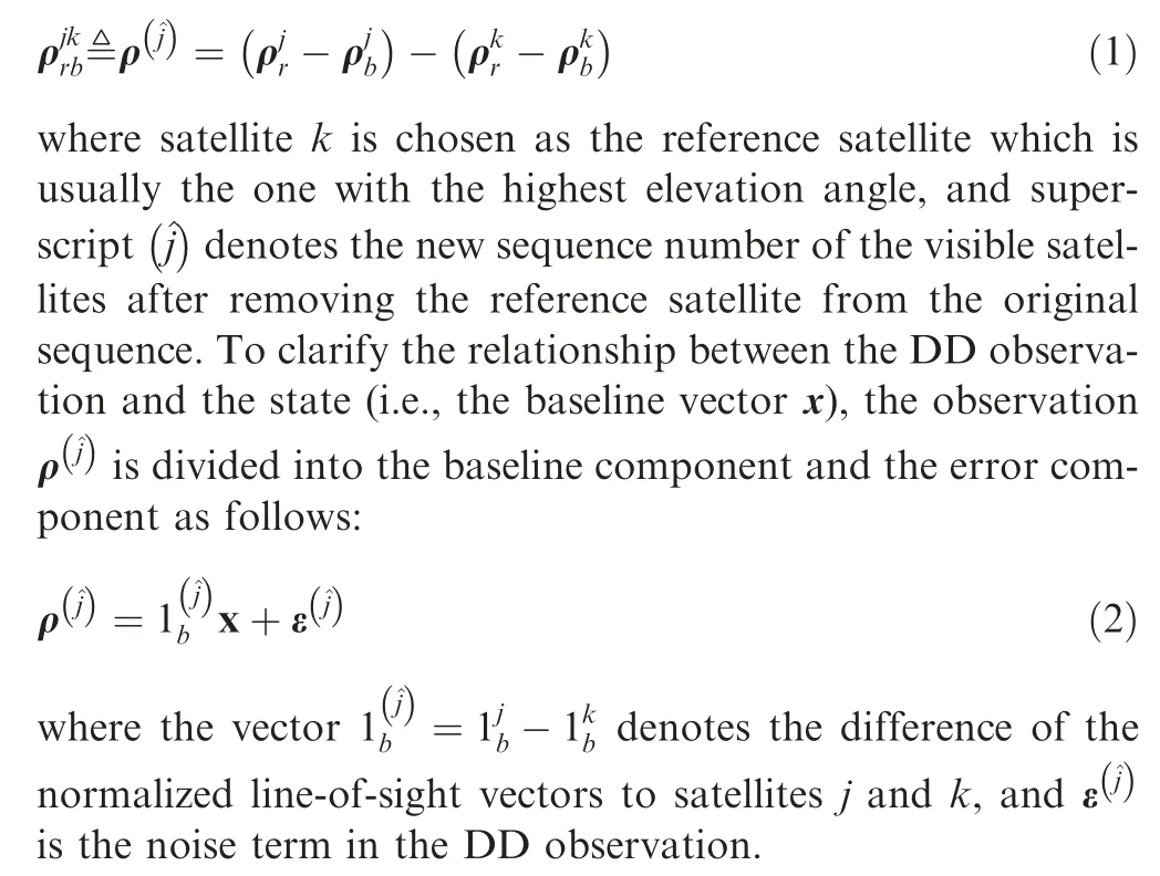
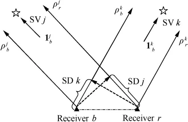
Fig.1 Formation of GNSS single difference observations(SV=Satellite).
Given that one satellite should be chosen as the reference satellite, N satellites which are visible to both receivers are expected to form N-1 DD observations. Then the transfiguration and extension of Eq. (2) to N-1 DD observations are shown as

Since determining the unknown baseline vector x is at the heart of the matter, Eq. (3) will serve as the basis for further derivation.Similar to Single Point Positioning(SPP),the baseline vector can be estimated through a Weighted Least-Squares(WLS)method.At each iteration,the update for Δ^x is given by

where Δρrbis the vector of DD observations minus the expected DD values based on matrix A and the baseline solution given by the previous iteration. When the baseline solution has converged, the last Δρrbis defined as the residual vector yrb. In this equation, observations are weighted by the diagonal weighting matrix W. The weight for an observation depends on the associated error variance,which will be further illustrated in Section 2.2.
Finally, we intend to extend the relative positioning algorithm presented above so that it can employ dual-frequency observations from multiple constellations. The DFMC GNSS service is highly conducive to improving the relative navigation performance in that it will significantly optimize the satellite visibility as well as increase the redundancy. Moreover, the rapid development of receivers and antennas makes it convenient to exploit the DFMC GNSS service with low-cost and lightweight hardware. To utilize the measurements provided by DFMC GNSS,special attentions should be paid to the following technical aspects.First,for each constellation in use,we should select a satellite within it, usually the highest-elevation one, as the reference satellite. Second, to improve navigation accuracy, the uncombined approach where the individual signal of each frequency is treated as independent observation is preferred to the combined method, e.g., an ionosphere-free combination, because such a combination will greatly enlarge the error variance.
2.2. Error models
As illustrated in Section 2.1,most of the error sources in pseudoranges are eliminated by the DD processing technique, and multipath and receiver noise dominate the DD observation error budget. Properly characterizing measurement errors is essential to realize integrity monitoring in urban environments.This section aims at presenting the error model that characterizes the error distribution of DD observations in nominal conditions. Large errors caused by NLOS reception and heavy multipath interference are regarded as faults and excluded from this model. Specifically, to accommodate integrityrelated applications, conservative models are used to bound the errors with large magnitude and low probability. Furthermore, in order to cover various scenarios, we provide two different models for code-only measurements and carriersmoothed code measurements, respectively.
Stable carrier-phase observations are available in some situations where high-end receivers are used or the signal quality is favorable (e.g., in open-sky environments). In these situations,the multipath and receiver noise in the SD measurement corresponding to satellite j (SDj=) can be modeled as15
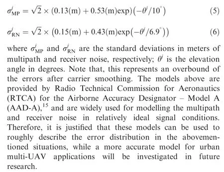
In contrast,unsmoothed pseudoranges will be employed for relative navigation in GNSS-challenging environments due to the limited availability of stable carrier-phase measurements.This situation usually arises when low-cost receivers are utilized in urban dynamic applications.In this situation,the nominal error models for the multipath and receiver noise in the SD observation are given by10

These models represent the overbounding results considering various receiver configurations and signal modulations with the following constraints: (A) the elevation angle is greater than 10°; (B) the signal-to-noise ratio (C/N0) is higher than 35 dB-Hz.
Then the SD measurement error diagonal covariance matrix CSDcan be determined by combining the effects of multipath and receiver noise as follows:

Based on Eq. (1), we compute the DD measurement error covariance matrix CDDas

where B denotes the(N-1)-by-N transformation matrix from SD to DD, which is given by
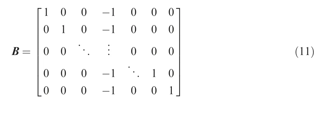
where all the entries in the kth column (corresponding to the reference satellite) are equal to -1.
Afterwards,the weighting matrix W is determined based on the covariance matrix CDD.In this paper,the weight of the^jth DD measurement is equal to the reciprocal of the associated variance, as shown in the following equation:

2.3. Fault sources, characteristics, and fault grouping
Contrary to absolute positioning systems where the majority of faults are attributed to the space segment,26relative navigation systems are mainly subject to faults resulting from the receivers. Though the vehicles usually fly at high altitudes in most multi-UAV applications,1they may occasionally encounter tall buildings which might interfere their GNSS receivers.As shown in Fig. 2, the large measurement errors caused by NLOS reception and heavy multipath interference are regarded as faults due to their potential to result in enormous navigation errors. In urban canyons, multipath and NLOS could induce the pseudorange error ranging from several meters to hundreds of meters, which seriously threaten the safety of multi-UAV formation flight.
Because the fault events are mainly provoked by flat surface reflectors presenting in the urban environment, their occurrence may be spatially dependent. For detailed illustration,Fig. 3 shows the signal condition in a scenario where a drone is surrounded by buildings. The buildings can not only block some direct signals but also generate reflected signals. The reflection may seriously interfere multiple signals from similar directions and lead to the faults in the associated pseudoranges. Therefore, the fault-independent assumption made in aviation domain is not true in this case, and the occurrence of multiple faults may be relatively frequent.
To accommodate the spatial dependence in the faults, we present a new preprocessing strategy, called fault grouping,whose basic idea is to divide the low-elevation satellites into several non-overlapping groups. Through employing skyplot,a preliminary grouping process is implemented with the following criteria: (A) the neighboring satellites should be separated into two segments if their azimuths differ by more than 45°;(B)the segments whose width(i.e.,the maximum azimuth difference)exceeds 60°always need to be divided again.Fig.4 presents an example of grouping results. After fault grouping,it is justified that the faults affect each group independently.In the integrity monitoring framework below, the probability of independent group failures is termed as group fault probability.
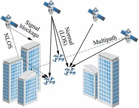
Fig.2 Illustration of the causes of faults in GNSS measurements under urban circumstances.
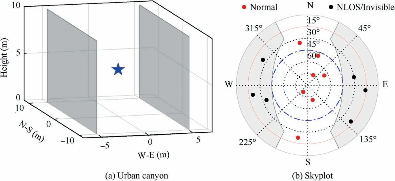
Fig. 3 Illustration of satellite signal condition in urban canyon.
3. Integrity monitoring of relative navigation systems
3.1. Definition of relative protection level
Protection Level (PL) is an important parameter of the integrity concept, which is originally introduced for evaluating the performance of absolute navigation systems in aviation applications. The PL is a statistical error bound computed so as to guarantee that the probability of the absolute position error exceeding the said number is lower than or equal to the target integrity risk.11Another important parameter is Alert Limit(AL) which represents the largest position error allowable for safe operations.In aviation domain,the navigation system is declared unavailable when the PL exceeds the corresponding AL in the vertical direction or in the horizontal plane.
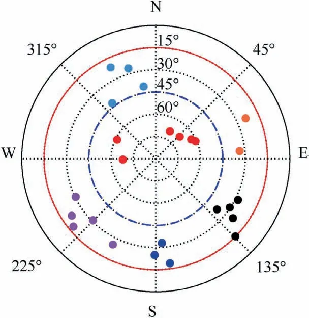
Fig. 4 Grouping result for the satellites with elevation angles below 45° (each color represents a group).
In this paper, we leverage the PL and AL concepts to the relative navigation context.For a relative positioning problem,a hazardous event occurs when the relative navigation error exceeds the estimated baseline ^x along the direction of ^x. This is because the actual distance may be very short in this case.Therefore, Relative AL (RAL) is defined as the estimated distance between two user receivers. Similar to PL in absolute positioning,Relative PL(RPL)is a probabilistic upper bound on the relative positioning error along the estimated baseline vector direction. Fig. 5 presents a graphical illustration of the definitions above using a two-dimensional collision avoidance example.In the figure,the estimated baseline is expressed in a local ENU frame with UAV A as the origin. RPL is presented as half the length of a segment in the estimated baseline direction, and the segment, centered at the estimated baseline(i.e., the estimated position of B relative to A), describes the one-dimensional region assured to contain the true baseline component in this direction. The RPL is computed so as to guarantee that the probability of the true baseline component being outside the region is equal to the target integrity risk.The operation is declared to be safe when RPL is smaller than RAL (the left case in Fig. 5). Conversely, the right case in Fig. 3 corresponds to a dangerous situation.
From another perspective, the RPL also indicates the minimum required safety distance between UAVs in a given direction. Specifically, it is dangerous for UAVs to maintain a shorter distance than the corresponding RPL in a specific direction because the relative navigation output is not reliable enough to provide the collision avoidance service in this situation. Furthermore, the safety envelope of a UAV, describing the safety distances in all directions, can be obtained by computing the RPLs for each direction. The envelope provides a no-entry space of a UAV, and any UAV intruding into this space will lead to a considerable risk of collision.
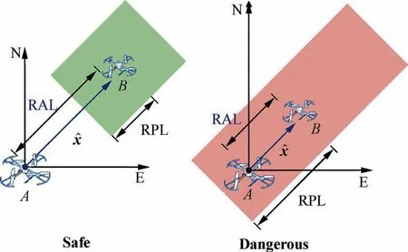
Fig. 5 A graphical illustration of RAL and RPL using a twodimensional collision avoidance example.
3.2. Fault detection based on multiple hypotheses solution separation
FD is an essential technique included in the integrity monitoring framework to ensure navigation integrity by exploiting redundant range measurements. The Multiple Hypothesis Solution Separation(MHSS) approach,a widely implemented RAIM/ARAIM method for FD,15is also employed in this paper to realize the integrity monitoring of relative navigation systems. MHSS offers several obvious advantages: First, it admits and copes with multiple simultaneous faults; second,it provides a straightforward proof of safety and a direct way to calculate the protection levels.27Based on MHSS, the procedures of the proposed FD method are illustrated as follows.
First, we determine the subsets that need to be monitored,each of which corresponds to a fault mode.Based on the prior probabilities of independent fault events, we establish a list of monitored fault modes and calculate the associated maximum number Nf,maxof simultaneous faults by leveraging the approaches given in the ARAIM algorithms.15,28At the same time,we compute the fault probabilityof each subset and the probability of unmonitored modes PNM.It is important to note that each group is regarded as an individual‘‘satellite”in this process.
Particular attention should be paid to the fault affecting the reference satellite. In this paper, the fault occurring in the reference satellite is termed as constellation fault because it can impact all the DD observations within the associated constellation. Therefore, reference satellites usually have high elevation angles so as to guarantee low probability of constellation fault. Additionally, it should be mentioned that the groups do not belong to any constellation,but the satellites in them are independently affected by the corresponding constellation fault.
Based on the solution separation method, a fault detector involving all monitored fault modes is described in detail as follows.15For subset i,we firstly compute the diagonal weighting matrix:
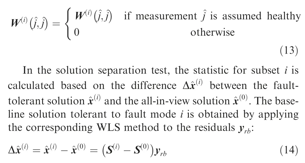
where the coefficient matrix Si() is given by
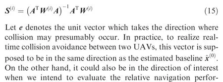
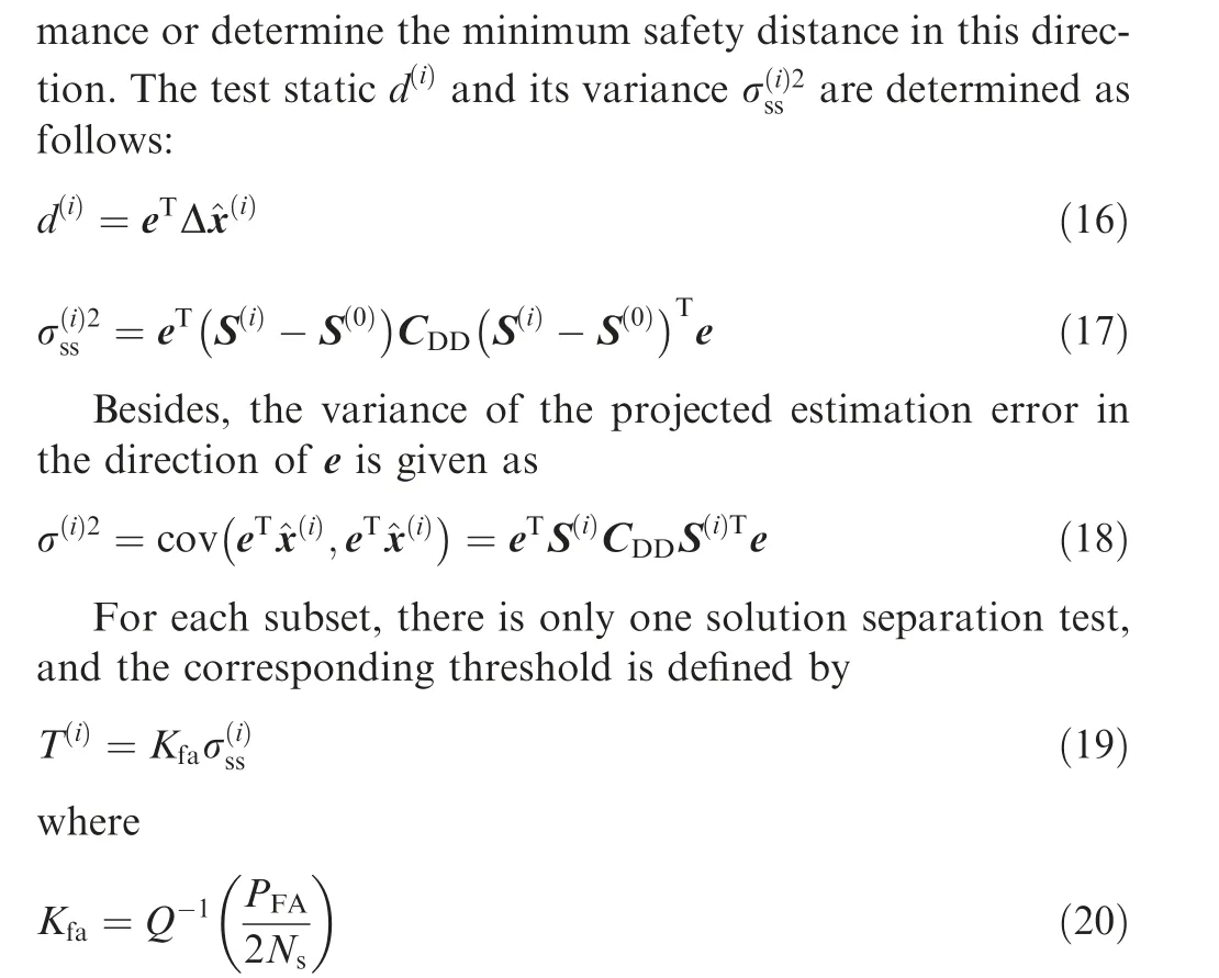
where Q-1(p ) is the (1-p) quantile of a zero-mean unitvariance Gaussian distribution; PFAis the false alarm probability which represents the continuity budget allocated to disruptions because of false alert; Nsdenotes the number of monitored subsets.The protection level can be computed only for all i and thus we have the following:

If any of the tests fails,the fault detector will issue an alarm and exclusion must be attempted.
3.3. Fault exclusion scheme design
Fig. 6 presents the flowchart of the proposed fault detection and exclusion scheme. As seen, the role of fault exclusion is to identify and exclude the faulted measurement(s) when an alert is raised by the fault detector. Following the procedures shown in this figure, the detailed process of fault exclusion is illustrated as follows.
To find a consistent (i.e., no fault alert) subset, the algorithm may have to exclude a set of satellites of size Nex. For each possible value of Nex,from 1 to Nf,max,the best candidate subset for exclusion,i.e.,the one most likely to be consistent,is determined as15

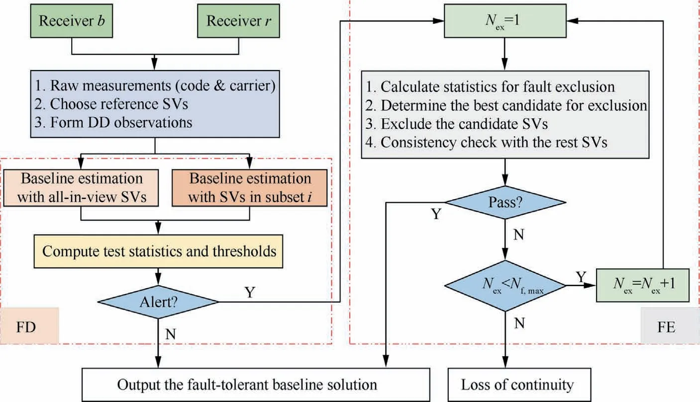
Fig. 6 Flowchart of the proposed fault detection and exclusion scheme.
3.4. Quantifying navigation performance in terms of integrity and accuracy
To quantify relative navigation performance in terms of integrity and accuracy, the RPL and the accuracy should be determined. First, we provide an approach to determine the RPL that can satisfy specific integrity requirements. For the given target integrity risk, i.e., Probability of Hazardously Misleading Information (PHMI), the mathematical definition of the RPL is described as

The MHSS method provides a straightforward way to compute the RPL by solving the following equation:

where the term in the left-hand side denotes the integrity risk allocated to the monitored fault modes, and each term in the right-hand side is an upper bound of the contribution of a fault mode (including the fault-free mode, i.e., the first term) to the total integrity risk. A detailed derivation of this equation and an effective method to solve it can be found in the ARAIM baseline algorithm description.15
Accuracy is a parameter which describes the error distribution under nominal(i.e.,fault-free)conditions.In this paper,it is employed to quantify the difference between the actual formation geometry and the desired one induced by navigation uncertainty. The accuracy can be represented by the standard deviation of the relative navigation error. According to Eq.(18), the accuracy in the direction of e is given by

4. Experiments and results
4.1. Simulations for performance evaluation and sensitivity analysis
To conduct worldwide navigation performance evaluation,we build a simulation platform through modifying the MAAST software which is a publicly available GNSS toolset for integrity algorithm simulation and performance evaluation.29,30In the simulations, users are simulated on a 10-by-10-degree grid in the world map, for a period of 10 sidereal days with a time step of 1 hour.Table 1 gives the input parameters of the integrity monitoring algorithm.Though these values stem from aviation domain,15they can also be employed here to represent typical integrity and continuity requirements of integrityrelated applications. Table 2 shows the setting of 9 simulated scenarios which are meant to represent various receiver configurations and different operational environments.Note that,in Table 2, an urban environment represents the scenario where the vehicles fly at a low altitude relative to the local buildings.
It is important to note that integrity risk and false alert probability should be entirely assigned to the direction of inter-est,rather than allocated to the vertical direction and the horizontal plane.To reveal performance variation with directions,we compute the eastward, northward, and upward relative protection levels (EPL, NPL, and UPL), respectively. The accuracy is also calculated and here it refers to the standard deviation of 3D relative position errors. As these indicators are time-varying due to satellite motion, we quantify the performance by four statistical indices (for EPL, NPL, UPL and accuracy,respectively)of 99.5%availability for each user.The index of 99.5% availability means that the actual values are lower than the said number during 99.5% of the time.The results and discussion are presented in detail as follows.
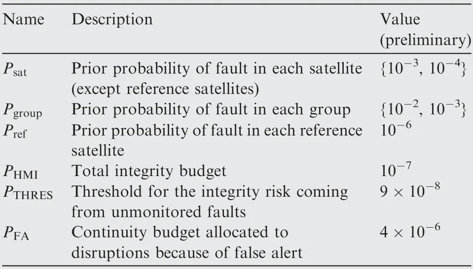
Table 1 List of input parameters.

Table 2 Simulation configurations in various scenarios.
We firstly analyze the sensitivity of relative navigation performance to receiver configurations by comparing Case 1 with Case 3.In the two cases,we simulate a low-cost receiver and a high-end one, respectively. Figs. 7, 8 and 9 reveal the significant performance improvement in terms of both RPL and accuracy offered by the high-end receiver. Therefore, it is evident that the performance heavily depends on receiver configurations.
In addition,we investigate the effect of environmental conditions on the performance by simulating a middle urban scenario. Taking Case 5 as an example, the results shown in Figs.9 and 10 suggest that compared to Case 3,the navigation system encounters serious performance degradation in this case. This proves that environmental conditions also exert a profound impact on the performance.
Figs. 11 and 12 provide a direct view of the comparison among all the cases in order to quantify the impacts of various factors on the performance. To measure the overall performance, the results are presented in the form of Cumulative Distribution Function (CDF). CDF specifies the normalized frequency that a variable X takes a value less than or equal to a given value x.According to the comparison,we can draw the following conclusions:
(1) A noticeable performance improvement can be achieved by smoothing pseudoranges with carriers, although it may come at the cost of expensive hardware or instable navigation output in urban environments;
(2) The performance can also be greatly improved by utilizing dual-frequency signals (Case 1 vs Case 2) and exploiting more constellations(Case 2 vs Case 3),which illustrates the importanceof employing DFMC receivers;
(3) Compared to non-urban scenarios, the overall performance could be dramatically degraded in urban environments. This is because, for one thing, the measurement accuracy decreases due to employing unsmoothed pseudoranges(Case 3 vs Case 4),and the number of satellites in view also reduces(Case 4 vs Case 5).For another,setting a high fault probability (Case 4 vs Case 6) for the low-elevation satellites and/or grouping them (Case 4 vs Cases 7–9)are/is expected to make the integrity monitoring algorithm well suited for urban applications,but meanwhile this will lead to obvious degradation in navigation performance. The results also suggest that both the group fault probability (Case 7 vs Case 8) and the grouping criterion (Case 7 vs Case 9) exert obvious impacts on the RPLs.
4.2. Flight test and experimental results
The objective of flight experiments is to validate the proposed integrity monitoring framework with real data. For this purpose,a multi-UAV test platform is set up based on two assembled quadcopters.As shown in Fig.13,each UAV is equipped with several devices used for data collection. A lightweight DFMC GNSS receiver, ublox F9P, is utilized to output raw GNSS measurements including pseudoranges and carriers.The data are recorded and stored via RTKLIB, an opensource GNSS software,31on the on-board computer (i.e.,Raspberry Pi 3B+). The network RTK subscription service,i.e., FindCM provided by Qianxun SI,32is exploited to compute the reference position solutions of the UAVs. Besides, a MATLAB-based software is developed to post-process the data collected during the flight.
The flight experiment was carried out in the campus where many satellite signals were available and favorable GNSS positioning performance was achieved. In this experiment, the UAVs were set to autonomous flight mode to track the preset flight paths that last about 2 minutes. The true trajectories of the vehicles, visualized by Google Earth, are shown in Fig. 14. Specifically, for safety concerns, the two vehicles flied in opposite directions(red:clockwise;green:counterclockwise)at different heights above the ground (red: 20 m; green: 8 m).

Fig. 7 Relative protection level world map for Case 1.

Fig. 8 Relative protection level world map for Case 3.

Fig. 9 Three-dimensional accuracy world map for three cases.

Fig. 10 Relative protection level world map for Case 5.
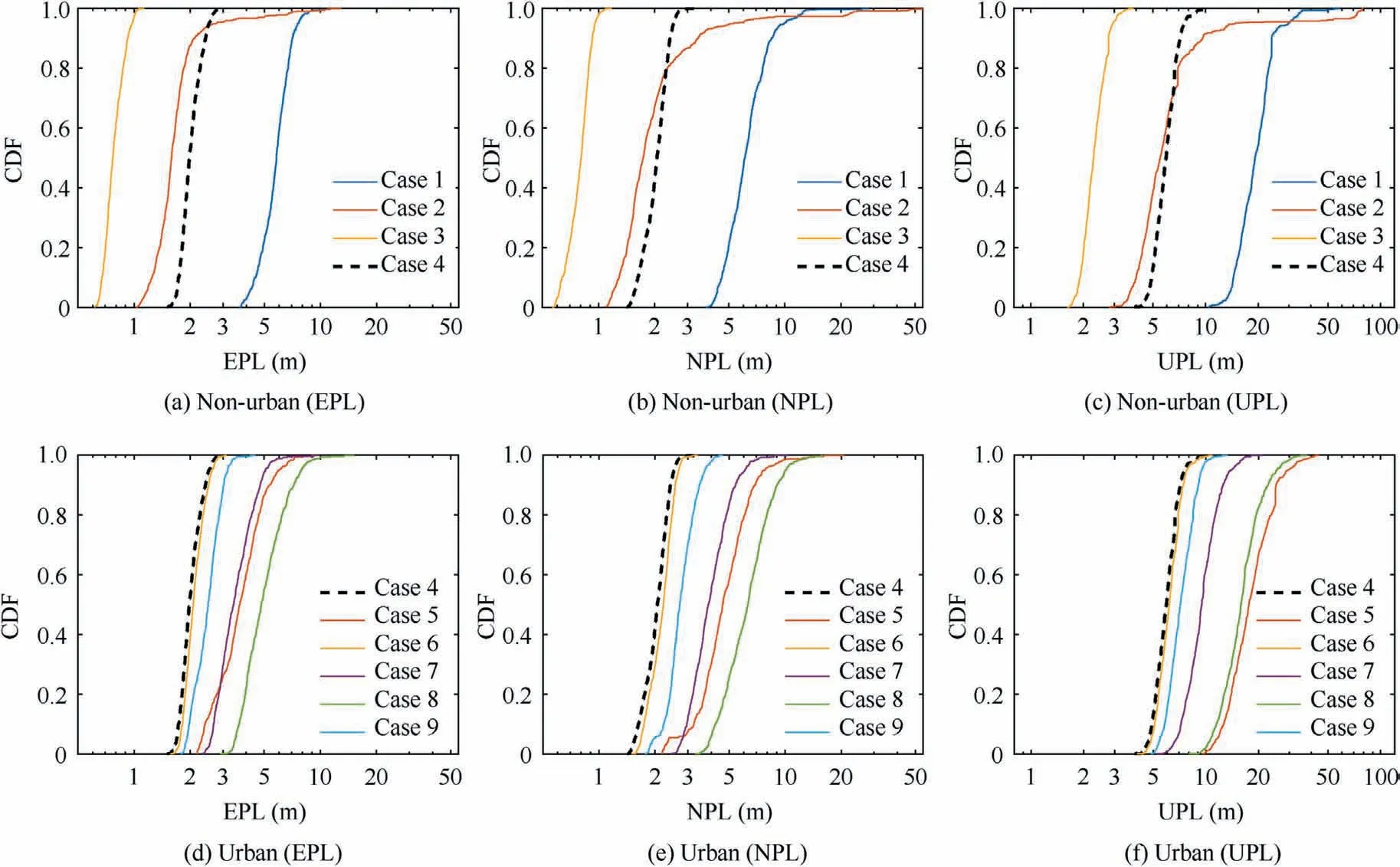
Fig. 11 A comprehensive comparison of relative protection levels among all the cases.
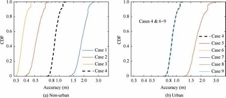
Fig. 12 A comprehensive comparison of accuracy among all the cases.
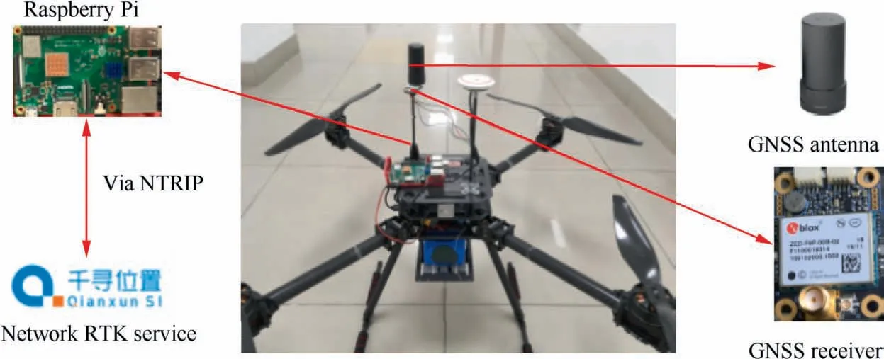
Fig. 13 Experimental UAV system featuring a GNSS receiver, antenna and Raspberry Pi.
Firstly, we conducted data preprocessing as follows. The receiver elevation mask angle was set to 15 degrees, and the observations with C/N0below 35 dB-Hz were manually removed. In addition, we performed data quality check with the open-source BNC software33to analyze the carrier stability.Fig.15 presents the skyplot of the satellites used in the following analyses. The number of visible satellites is 14, which can well represent the data redundancy in a middle urban scenario.17For each constellation, the satellite with the highest elevation was chosen as the reference satellite, i.e., G25 for GPS and C06 for Beidou. Beidou GEO satellites were absent here because they were not supported by ublox F9P.
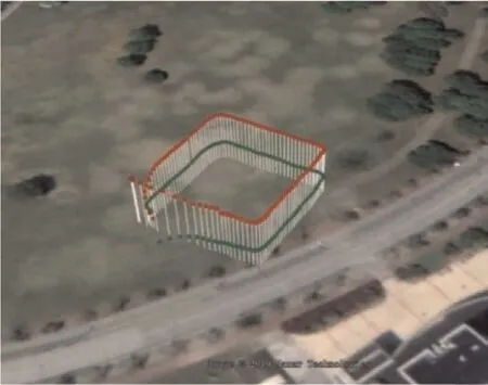
Fig. 14 Flight trajectories of the UAVs.
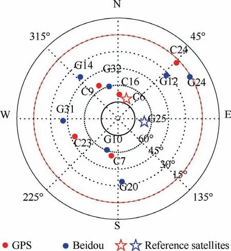
Fig. 15 Skyplot of the satellites in use (blue: GPS; red: Beidou;star: reference satellites). (For interpretation of the references to colour in this figure legend, the reader is referred to the web version of this article.)
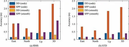
Fig. 16 Accuracy comparison between two relative navigation methods in the form of RMS and STD.
Using the collected data, we compare the relative navigation accuracy between the pseudorange DD method and the position difference approach. The relative positioning errors are reported with respect to the reference trajectories determined by the RTK technique. To perform a fair comparison,we exclude some satellites (i.e., G14, G20, G24, C23, and C24) which are either with only single-frequency observations or with unstable carriers.Fig.16 compares the relative navigation accuracy of the two methods in the form of Root Mean Square (RMS) and STandard Deviation (STD). In this figure,DD means pseudorange DD and SPP denotes position difference. As seen, the pseudorange DD method achieves superior performance to the position difference approach. The results also suggest that carrier smoothing is an effective approach to improve navigation accuracy when there are stable and continuous carrier-phase observations.
To represent a typical urban scenario, we employ the unsmoothed pseudoranges in the following analyses.We apply fault grouping to the satellites with elevation angles below 45 degrees, and G12, G24 and C24 form a group (labelled as Group1). Then the performance of the FDE scheme is validated under both single-fault and multi-fault scenarios. The two scenarios are simulated by manually injecting 10-meter faults to satellite G20 and to both G20 and Group 1, respectively. Fig. 17 presents the relative positioning errors of the DD method under the multi-fault scenario.As seen, the faults lead to unreliable baseline estimates,and they may increase the collision danger consequently.
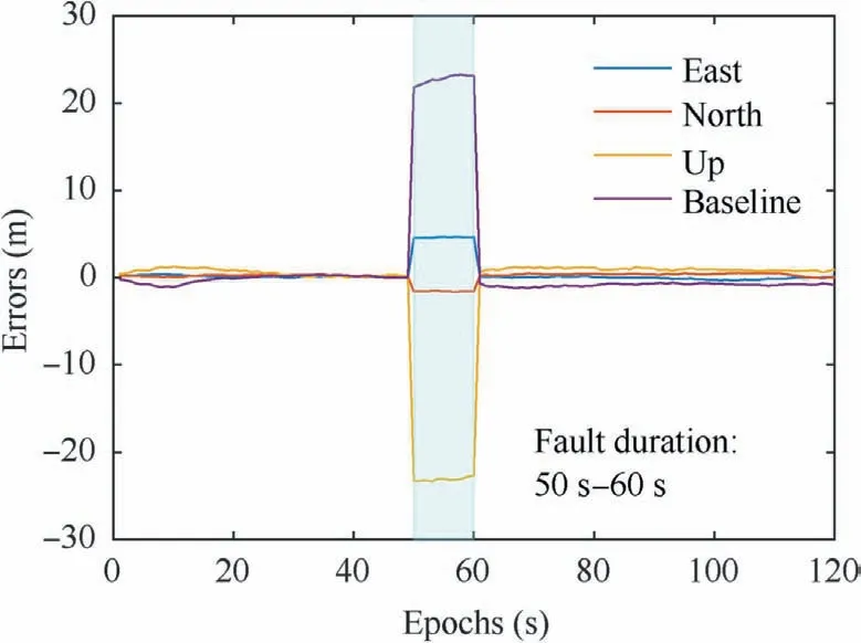
Fig. 17 Relative positioning errors in multi-fault scenario.
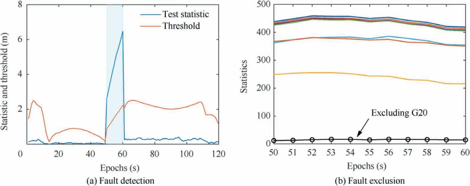
Fig. 18 Results of fault detection and fault exclusion in a single-fault scenario.
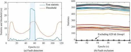
Fig. 19 Results of fault detection and fault exclusion in a multi-fault scenario.
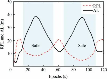
Fig.20 Relative Protection Level(RPL)and the ssociated Alert Limit (AL) in flight experiment.
Fig.18 gives the results of FD and FE under the single-fault condition. The threshold in FD is time-varying because of the variation in the direction of the estimated baseline. Fig. 18(a)indicates the effectiveness of the fault detector under a single-fault scenario. Additionally, Fig. 18(b)shows the statistics for every single-fault exclusion candidate, among which excluding G20 corresponds to the smallest one. According to the FDE flowchart,G20 will be excluded,which demonstrates the feasibility of the FE method.Similarly,Fig.19 presents the results under the multi-fault scenario. In this case, because no consistent subset can be found by excluding a satellite or a group, the FE algorithm attempts to exclude multiple satellites. Fig. 19(b) suggests that it makes the right decision, i.e.,excluding G20 and Group 1. Therefore, the results prove the promising performance of the FDE scheme under multi-fault conditions.
Finally, Fig. 20 provides an example to illustrate how to warn collision dangers with relative protection levels. In this figure,we compute the RPL in the estimated baseline direction under the fault-free condition, adopting the same fault probability as Case 7 in Table 2.The RPL represents the error bound of the baseline estimate and the AL is the estimated distance between two UAVs. Therefore, the vehicles may actually be perilously close to each other when the estimated distance is shorter than the RPL. In Fig. 20, the blue shading represents a safe state while the rest indicates that the vehicles may be exposed to the danger of collision. Accordingly, to guarantee the safety of multi-UAV systems, it is highly desired to calculate the RPL for any two potentially conflicting vehicles in real time.
5. Conclusions
A high-reliability relative navigation system utilizing double differenced pseudoranges is developed to reduce collision risk in multi-UAV systems under urban circumstances,and is evaluated in various scenarios by simulations and experiments.The following conclusions can be drawn from this study:
(1) Employing dual-frequency signals from multiple constellations can significantly improve the relative navigation performance in terms of both accuracy and integrity, which indicates that Dual-Frequency Multi-Constellation(DFMC)GNSS is highly desired in urban multi-UAV applications.
(2) Environmental conditions also greatly impact the navigation performance through influencing satellite visibility, measurement accuracy, fault probability and fault characteristics. As a result, compared to the operation in open-sky areas, a sparser formation geometry is required to avoid collision during the flight in urban environments.
(3) The Relative Protection Level(RPL)is a measure of the minimum allowable safety distance, and it varies with the direction of the baseline.The simulation results indicate that in most scenarios with DFMC GNSS receivers,the RPL values are below 5 meters, 5 meters, and 15 meters in the East, North, and Up directions,respectively.
(4) Experimental results suggest the superior navigation performance of the double difference method to simply differencing two absolute position estimates, and prove the effectiveness of the proposed fault detection and exclusion scheme in both single-fault and multi-fault scenarios. In addition, the experiments also illustrate how to warn collision danger with the RPL and the estimated baseline in real time.
(5) The proposed integrity monitoring framework allows both offline performance prediction and real-time collision risk evaluation.The user can predict the achievable relative navigation performance as long as the formation geometry,flight trajectory and receiver configuration are specified.This is beneficial to the design and application of multi-UAV systems. This framework also helps assure operation safety during the flight through coping with faulted measurements and evaluating the risk of collision in real time.
Declaration of Competing Interest
The authors declare that they have no known competing financial interests or personal relationships that could have appeared to influence the work reported in this paper.
Acknowledgements
The authors would like to thank Prof. Hugh H.T. Liu from Institute of Aerospace Studies, University of Toronto (UoT),Toronto, Canada, for kindly providing the knowledge about the applications of multi-UAV systems. We also thank Xiyu Liu from School of Aeronautics and Astronautics, Shanghai Jiao Tong University, Shanghai, China, for her contributions to the experiments conducted in this work. This study was co-supported by SJTU Global Strategic Partnership Fund(2019 SJTU–UoT)and Master Research Agreement between SJTU and Honeywell Technology Solutions China (HTSC).
 CHINESE JOURNAL OF AERONAUTICS2021年7期
- CHINESE JOURNAL OF AERONAUTICS的其它文章
- Integrated batteries layout and structural topology optimization for a solar-powered drone
- Polynomial networks based adaptive attitude tracking control for NSVs with input constraints and stochastic noises
- Morphing wing flaps for large civil aircraft:Evolution of a smart technology across the Clean Sky program
- Review on bio-inspired flight systems and bionic aerodynamics
- SARISTU:Adaptive Trailing Edge Device(ATED)design process review
- Continuous morphing trailing-edge wing concept based on multi-stable nanomaterial
