Performance of wavecatcher intakes at angles of attack and sideslip
Fengyun ZUO, Snnu MO¨ LDER, Gng CHEN
a State Key Laboratory for Strength and Vibration of Mechanical Structures, School of Aerospace Engineering,Xi’an Jiaotong University, Xi’an 710049, China
b Ryerson University, Toronto ON M5B 2K3, Canada
KEYWORDS Angle of attack;Sideslip angle;Unstart;Wavecatcher intake
Abstract A wavecatcher type scramjet intake, that reduces the Mach number number from 4 to 1.552, is used as the basis for a study of flow starting/unstarting as affected by freestream angles of attack and sideslip. The intake design is based on a morphed streamtube consisting of two conical flow streamlines using streamline tracing and osculating axisymmetric design theory. Intake flow and performance is modeled using the numerical CFD code and the k-ε turbulence model.The intake unstarts at a sideslip angle of 2°, a positive angle of attack of 1°. Both positive angle of attack and sideslip angle have an adverse effect on the startability of the MBus intake. At negative angles, the intake initially unstarts at -5° angle of attack, due to the thickened shear layer induced by the streamwise vortex.Then it re-starts at-8°angle of attack,mainly due to the expansion fan formed at the leading edge, causing the shock wave structures inside the intake to be reestablished.
1. Introduction
The key components of the hypersonic or high-speed airbreathing propulsion system are the intake,combustion chamber and nozzle.1The hypersonic intake decelerates and compresses the airflow as it flows into the combustion chamber.Hypersonic wavecatcher intakes, that utilize an axisymmetric,compressive parent flowfield and have specified entrance and exit shapes, are receiving increasing attention because of their high performance (capability and efficiency).2–5General research results on wavecatcher intakes have been summarized and reviewed by Zuo and Mo¨lder(2019).6It is pointed out that the most effective feature of this type of intake is an internal converging flowfield rather than planar flow elements. The axisymmetric wavecatcher intake attains most of its compression by flow convergence rather than flow turning or shock deflection. The converging flow is isentropic which leads directly to efficient intakes with high capability. Problems of viscous losses and flow starting are eased by use of wavecatcher technology, providing leading edge truncation and sweep and by the fact that high adverse pressure gradients occur in the inviscid flow rather than in the boundary layers.Bulman and Siebenhaar (2006)7compared the three general classes of intakes (outward turning, planar and inward turning) with an intake design point of Mach number number 10. It was found that the wavecatcher (inward-turning) intake is attractive for scramjet applications due to the small wetted area that led directly to an increased intake performance as well as a reduction in engine heat load.
Historically, a large number of articles have conducted indepth studies on the angle of attack characteristics of traditional supersonic intakes (planar, outward turning). A F/A-18 supersonic planar intake was investigated at a high angle of attack (30°) at Mach number number 0.2. Numerical simulation,showed that the reduction of inlet mass flow had a small effect on the external flowfleld.8A high-speed civil transport mixed compression axisymmetric inlet at Mach number 2 and 2° angle of attack was investigated numerically in Refs.9,10. The computed maximum angle of attack that the inlet could sustain before unstart was in good agreement with experiment. For the Mach number 2.0 case, the computed maximum angle of attack at which the inlet remained started was 1.4° ± 0.2°, which is in close agreement with the experimental value of 1.3°. The effects of the angle of attack (0°–9°)were numerically studied on an outward turning supersonic intake at Mach number 2.1.11The results suggest that the distortion at the exit section decreases with increasing attack angle. Effects of angle of attack on buzz in the outward turning intake, at Mach number 2, were investigated experimentally.12
Based on the survey of the state of the art in supersonic intakes, the investigations were preliminary on planar or outward turning intake. We believe that further study of wavecatcher intake startability, unstarting and off-design operation – both Mach number number and flow alignment,is appropriate. The study of sideslip angle is still missing of such wavecatcher intakes. At off-design operating conditions the changes of incoming airflow necessarily alters the flow structures inside the intake, causing deviations from the original parent flowfield,even possibly leading to an intake unstart.Off-design performance determines the possible operating envelope of the propulsion system. The starting ability of an intake is a complex problem. A pitching motion will place the intake at an angle of attack, α, and a yawing motion will produce a sideslip angle, β. These are the inclinations of the freestream vector in the (x, y) and (x, z) planes of the intake.The combined misalignment of the freestream vector from the x-axis of the intake is γ, where sin2γ=sin2α+sin2β. For small angles γ2=α2+β2. Flow misalignment by γ makes the starting problems of wavecatcher intakes more complicated.For further details on starting ability of hypersonic intakes,see the Refs.13–16.Stable,high performance is expected from an intake. The aim of this paper is to supplement previous studies on wavecatcher intake design Zuo et al. (2016),17to include effects of attack and sideslip angle.The boundary limit between the start and unstart of the fixed-geometry wavecatcher intake is established for Mach number 4.0 in this paper. The off-design performance, coupled with previous deigned condition, are aimed to lay a foundation for comprehensive understanding of the flow characteristic and operating envelope of wavecatcher intakes.
The paper is organized as follows: The numerical methodology and turbulence model is described in Section 2; the description of wavecatcher intake geometry is given in Section 3;the results covering attack and sideslip-angle effects are presented in Section 4. Concluding remarks are in Section 5.
2. CFD methodology
In Reynolds-averaged Navier-Stokes equations, the instantaneous variables are decomposed into their mean and fluctuating components. In Cartesian coordinates, the equations are cast in conservation form as follows:

τijis the Reynolds stress tensor, which arises from the timeaveraging procedure on the non-linear, convective terms in the momentum equations, and which contains all the effects of the turbulence on the averaged momentum conservation.The same concept applies to the heat flux Qi^E(and ^H)is introduced in order to use the same state relations of the instantaneous quantities also for the averaged ones.k is the turbulence kinetic energy. H and h are, respectively, total enthalpy and enthalpy.
The Reynolds-averaged Navier-Stokes equations were adopted in this paper with compressible flow using a finite volume time-marching approach. A calorically perfect gas model was used. Turbulence was modeled using the two equation Realizable k-ε mode, see in Appendix A. The inviscid flux was evaluated using Roe’s flux-difference splitting, adapted to the preconditioned system. An implicit algorithm with second-order upwind scheme on flow equations, first-order upwind on turbulent kinetic energy and turbulent dissipation rate were applied in the calculations. The designed flight altitude of Mach number 4 wavecatcher intake is at 24 km with free-stream static pressure 2930.7 Pa,and the free-stream static temperature is 220.65 K; the free-stream viscosity is 1.444×10⁻⁵kg/(m·s). So the unit Reynolds number is 3.8×10⁶/m. The intake is assumed to travel on a constant dynamic pressure trajectory of q=33 kPa.
3. Description of intake geometry
The intake under study is designed for a freestream Mach number of 4. Its aerodynamic design and flowpath shape are based on two streamline elements of conically and axially symmetric flows, M-flow and Busemann flow, using the wavecatching principle. The Busemann profile is truncated to decrease intake weight and boundary layer losses. The truncated part is replaced by an M-flow profile. Hence we call it an MBus intake. Its aerodynamic performance is described in Section 4.
3.1. Parent MBus flow profiles made from M-flow and Busemann flow
The flowpath shape of the intake is based on the streamline shapes from M-flow (ICFA) and Busemann intake flow,namely MBus flow. The MBus (ICFC) flow was proposed in the Ref. 18, and the flow field combination is derived from two of the four types of axisymmetric, conical flow fields described by Grodzowskii (1959)19and Mo¨lder (1967).20The cardinal streamline, consisting of the tandem combination of M-flow and Busemann flow streamlines is shown in Fig. 1.M-flow forms the leading edge. It produces a nominally constant, conical leading edge shock. The trailing edge of the M-flow is joined to the leading edge of Busemann flow.21Leading edge of the parent Busemann streamline is truncated so as to join the M-flow. At the junction there should be a matching of surface locations, surface inclination and Mach number number. The first of these is essential to avoid a gap in the surface. It turns out that it is possible to satisfy only one of the two remaining conditions.We have chosen to match the Mach number numbers.
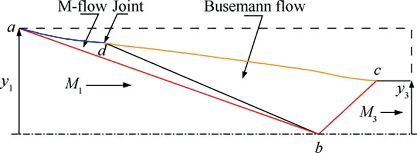
Fig. 1 MBus (ICFC) flow field, consisting of M-flow and Busemann flow which transform the uniform and parallel flow M1 to contracted and compressed uniform flow at M3.
Fig. 1 shows the MBus flow field, consisting of M-flow(ICFA) (Mo¨lder 1967)20and Busemann (B) flow,22which transform the uniform and parallel flow M1to the contracted and compressed uniform flow at M3. Both flows are axially as well as conically symmetric with a common focus at b and they obey the Taylor-Mccoll(T-M)equations(Mo¨lder 1967).20The M and B us flows are joined at the conical surface db.The cardinal streamline of the MBus flow consists of the M and B flow streamlines ad and dc, joined at d. The M-flow portion of the cardinal streamline is calculated downstream from the shock ab by integrating the TM equations from given values of M1and leading edge flow deflection, δ until the singularity db is reached at an angular location θdwhere the Mach number is Mad. This calculation produces the shock ab and the flow details in the region abd and on the singular cone bd. A T-M calculation is then started at the conditions in front of the conical shock bc, where the boundary conditions are calculated from a specified M3and a shock angle θ3, by requiring that the flow at the exit is in the freestream direction. The Busemann flow calculation proceeds in the upstream direction to θdwhere the Mach number is compared with Mad. An iteration is performed with the Busemann integration, on θ3, until the Mach number is equal to Mad. All the Busemann streamline coordinates are then scaled so as to produce a match at d with the M-flow. Unfortunately, this does not produce the same surface inclination angle at d and an expansion fan is produced at the resulting small convex corner. In this joining of the M and Busemann streamlines it should be noted that the Busemann streamline is truncated by the leading edge portion that it would have if it faced the freestream without the M-flow. A different, potentially improved, matching may be obtained by requiring that the surface inclinations be equal—in which case the Mach number numbers would differ at d.
The flow Mach number, incident shock angle and exit Mach number are taken as design parameters to illustrate the design of the MBus flow.The main design step of the ICFC flow is shown in Fig. 2. The steps of obtaining the MBus cardinal streamline are as follows:
(1) The Mach number number and the incident shock angle are first solved to obtain the M-flow.
(2) The corresponding truncated Busemann flow is obtained from a prescribed initial Busemann cone half-angle θ3,and the exit Mach number.
(3) The iterative calculation of the cone half-angle θ3is performed to obtain the required truncated Busemann flow by matching Mach number number and polar angle at the junction of the M and Busemann flows.
(4) The cardinal streamline is scaled to have its leading point at each of the prescribed leading edge points. A circumferentially closed envelope of these scaled streamlines forms the intake streamtube.
3.2. Flowpath shape – capture cross-section and morphing
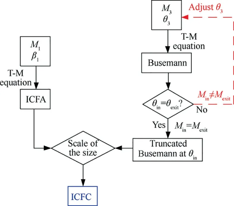
Fig. 2 Method of designing internal MBus parent flowfield.
Sobieczky et al. (1990)23has proven that a general 3D supersonic flow equation can be represented with second order accuracy by an axisymmetric flow equation, in which the axis is located in its osculating plane. This concept transforms three-dimensional, morphed wavecatcher intakes design into a series of two-dimensional osculating axisymmetric planes.Streamline tracing is then applied on each osculating plane to form the wall surface, where the streamlines come from the database of chosen parent flowfields.Arbitrarily modifying the flowpath cross section is called ‘morphing’ or ‘shape transition’.3,24Illustration of the morphing method is shown in Fig. 3 based on osculating axisymmetric theory. For detailed intake design information, please refer to Refs. 17,25.
Fig. 4 shows the capture and throat-section profiles of the wavecatcher intake in streamwise and spanwise (X-Z) projection. AD is the major axis of entrance-section ellipse; OO2is the half-minor axis of entrance-section ellipse.AD′is the major axis of throat-section ellipse; OO’ is the half-minor axis of lower throat-section ellipse; O’O1is the half-minor axis of upper throat-section ellipse. To ensure a smooth surface of wavecatcher intake based on streamline tracking technology,Points O,D′,D are on locate in a straight line and so are points O, A′, A.
The capture profile contains three straight lines and an ellipse line with BC=450.6 mm, and CD=90.1 mm. The major axis of captured-section ellipse is AD=450.6 mm;and the half-minor axis of captured-section ellipse is OO2=135.2 mm. The major axis of throat-section ellipse is A′D′=191.3 mm; the half-minor axis of lower throat-section ellipse is OO′=57.4 mm; the half-minor axis of upper throat-section ellipse is O’O1=41.3 mm. The internal contraction ratio of the wavecatcher intake is defined as follows.Take the center point from the lip and extend vertically upwards. The ratio of the intersected surface with the intake and the outlet surface serve as the internal contraction ratio ICR. The internal contraction ratio is approximately ICR=2.18, and the total contraction ratio is approximately CR=5.96.
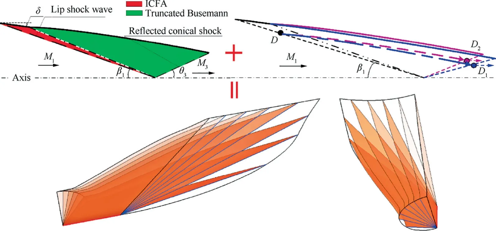
Fig. 3 Illustration of morphing method, based on osculating axisymmetric theory.
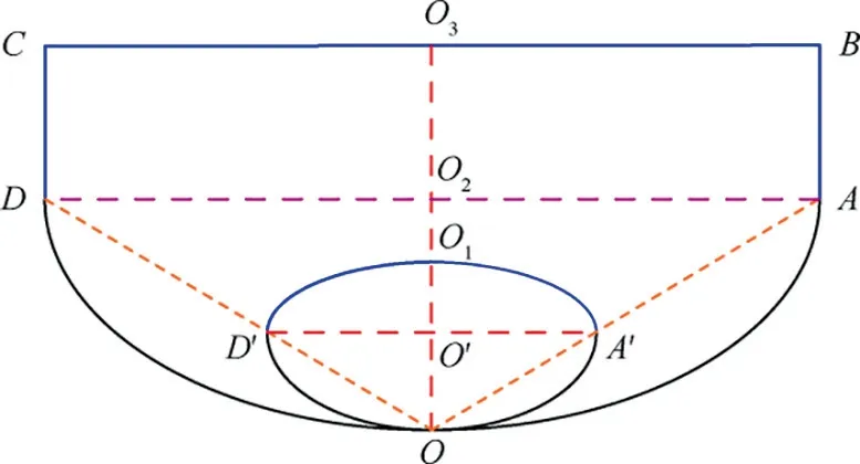
Fig. 4 Entrance- and throat-section shape of the Mach number 4.0 wavecatcher intake in X-Z projection.
After optimized shoulder smoothing and viscous effect correction, the final three-dimensional complex shape with morphed transition at design Mach number 4 is shown in Fig. 5.The viscosity correction method uses the Karman integral method to define turbulent boundary layers. The dimensionless parameters of the boundary layer, friction velocity u+and normal-wall distance y+, are obtained by an Inner Variable Approach developed in Ref. 26. Then the momentum integral equation is used to get the displacement thickness of the boundary layer. For detailed information, please refer to Ref.26.The captured profiles of this intake is similar to a rectangle;the throat-section profiles is similar to an ellipse,including two different half-elliptical lines;the exit-section profile is a circle. The divergent segment of intake is 13.1 times greater than the throat section’s equivalent diameter. The equivalent expansion angle of the diffusion is chosen 1.6°, which is suitable for decreasing airflow from supersonic to subsonic based on previous studies.4,27
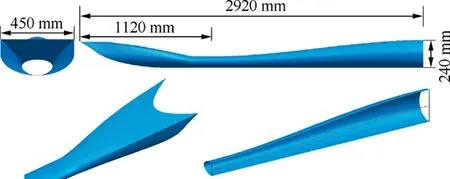
Fig. 5 Complex shape of wavecatcher intake with morphed transition.
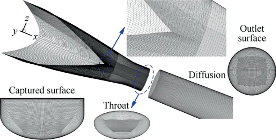
Fig. 6 Structured mesh of wavecatcher intake without showing surrounding domains.
The structured mesh of the wavecatcher intake is shown in Fig.6.The computational domains surrounding the intake are not shown.The mesh along wall-normal direction is refined to capture the turbulent boundary layer.The mesh near the lip of intake is also refined to guarantee the accuracy of captured incident shock. Note that to help visualize, the zoom size of captured surface, throat and outlet surfaces do not share the same values.The computational domain includes the flowfields surrounding the hypersonic intake and in the backflow duct.The right-side figure is the mesh blocks in the circular exit plane, which shows that the circle is built up of five blocks of O-grid. Actually, the O-grid starts from the beginning of captured surface to ensure and improve the quality of mesh.In order to improve the perpendicularity of the mesh near the lip of intake, the duct before the throat section is built of a two-layer O-grid.
Considering capturing the spillage airflow,the inflow is surrounded by a finite cylinder (not shown), which is about 6 times greater than the diameter of the entrance section. There are two additional blocks below the intake entrance to capture the possible spillage at off-design conditions. Based on previous experience with wavecatcher intakes and of a set of preliminary simulations, the domain has been discretized with a grid including 6.8 million nodes distributed in 45 blocks.Grid independence has been verified in previous studies.27The near-wall meshes are refined along the normal-wall direction with geometric proportion rule. The first normal-wall y+ maintains the same order of magnitude as the turbulent model verification in Appendix A. Because of the complexity of the geometry, the generated meshes are finally globally optimized.
The surrounding surfaces of the intake are set to the condition of pressure far filed. The entire wall surfaces were set to non-slip and adiabatic wall conditions. The flowfield solution was initialized at all grid points with the freestream flow conditions. Iterative convergence of each solution was evaluated through monitoring of the convergence of the flow rate,momentum, and energy equations. The steady-state solution was accepted converged when these values varied by less than 0.05%. The solution residuals were also monitored to check that they reduced and approached steady values. Assessment of turbulence model has been validated in Appendix A based on the external conical shock/wave boundary layer interaction.The numerical method in current simulations are accurate enough to capture flow structures in the wavecatcher intake by wind tunnel experimental data.28
4. Intake performance
The task of the Busemann flow is to receive the M-flow and to turn,contract and deflect it so that it compresses, decreases in Mach number number and takes up the freestream orientation.In this task the Busemann flow has a very high total pressure recovery, fundamentally because it does a lot of contraction and outward turning thus relieving the terminal shock from having to accomplish much loss-producing deflection. Therefore, it is precisely the outward turning of the Busemann flow that lead to its high efficiency.There is very little inward turning at the leading edge. For this reason, the Authors discourage the label ‘‘inward turning” when applied to high efficiency intakes. At the exit the Busemann flow produces an ideal uniform flow.
The task of the M-flow leading edge is to reduce the boundary layer losses, reduce the intake weight and to do so with a smooth junction to the Busemann flow. The flow deflection angle at the leading edge is 10° which produces a shock angle 22.2°and a total pressure recovery 0.925.The Mach number at the leading edge is 3.29, increasing to 3.14 at the trailing edge junction to the Busemann flow.
4.1. Aerodynamic performance, α=0° and β=0°
Contours of Mach number numbers in the symmetry plane of the wavecatcher intake are shown in Fig. 7 for Ma=4.0,α=0°and β=0°.The calculated flowfield is close in appearance to the parent flowfield at the design conditions of α=0°and β=0°.The incident shock wave is almost a straight,and the Mach number number after first shock is 3.4. Due to strong shock wave/boundary layer interaction,29a low-speed region appears near the throat zone, shown in Fig. 7(b). The initial shock keeps a conical shape,and converges to lip point.But the flow at the throat section is not uniform due to complex reflected shock waves (Fig. 7 (c)). Note that the flow in the intake is not affected by back-pressure.
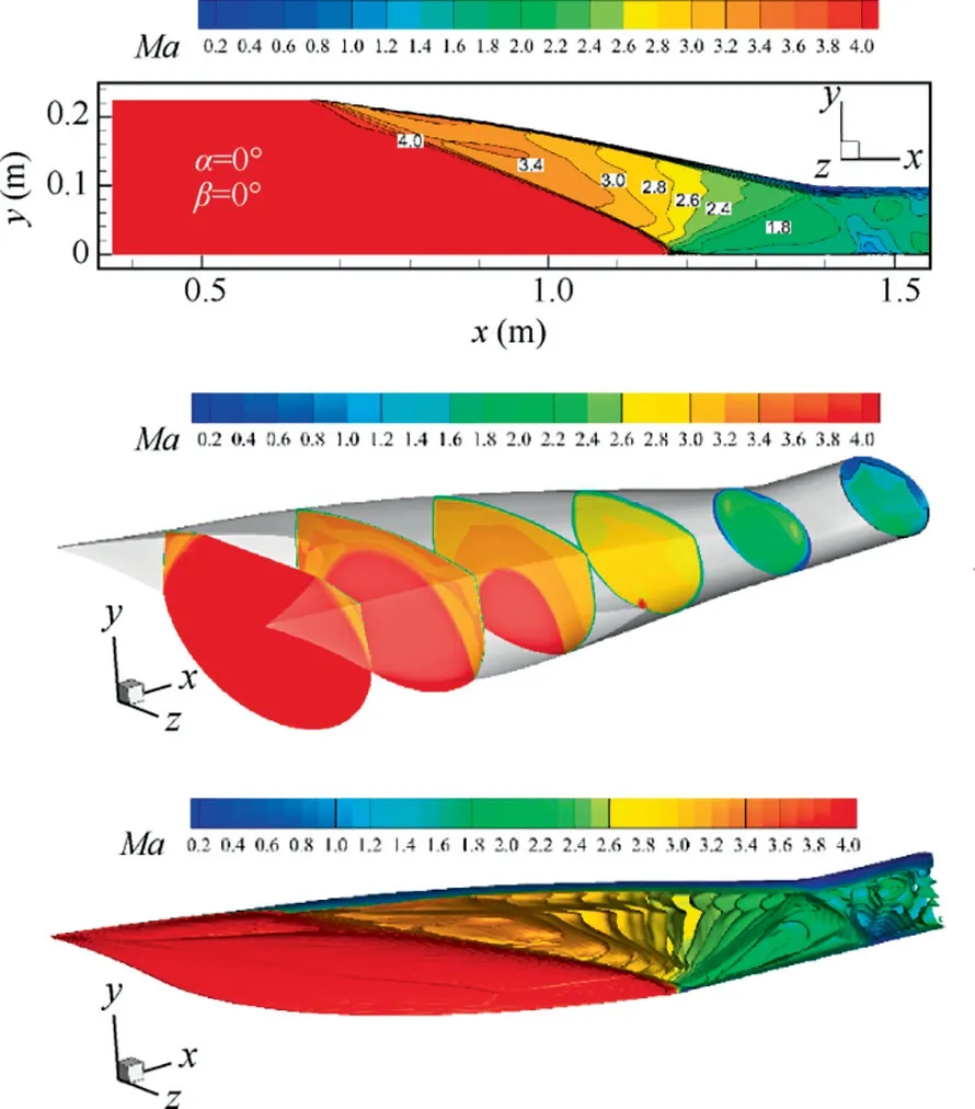
Fig. 7 Streamwise distributions and iso-surfaces of Mach number of wavecatcher intake before throat section at condition of α=0°, β=0°.
The three-dimensional streamlines of wavecatcher intake are shown in Fig. 8. The origins of the streamlines are evenly distributed in the captured cross section, and they are color coded by the local Mach number number. All the airflow is captured by the wavecatcher intake entrance,giving an airflow capture coefficient of 1.0.
Three-dimensional CFD calculations for α=0° and β=0°,in the morphed three-dimensional wavecatcher intake,have shown the following shock structure and flow characteristics:
(1) The initial shock wave is conical, which justifies the use of the M-flow axisymmetric, conical parent flowfield.
(2) The initial shock wave trends to be curved near the lower wall surface, and the flow area is continuously reduced.
(3) After the initial conical shock wave, the airflow undergoes isentropic compression again, the Mach number number along the streamwise direction is continuously reduced.
(4) The incident conical shock wave is reflected at the lip of the intake,and the flow begins to turn outwards,and the reflected shock wave almost restores the conical flow characteristic.
(5) The reflected shock interacts with the turbulent boundary layer which develops along the upper wall surface,resulting in conical shock wave/boundary layer interaction. This causes the boundary layer to thicken and detach leading to a deterioration in intake flow quality.
(6) Downstream of the first reflected shock there is a second reflected shock. The second reflected shock wave interacts with the parallel flow near the lower wall surface of the intake, inducing a weak normal shock near the throat section.
4.2. Performance at angle of attack
There is a design conflict between the airflow capture capability of the intake and the starting ability (startability). Spillage airflow of a wavecatcher intake occurs over the downstream leading edge. At the design condition there is no spillage because the incident shock wave attaches perfectly to the lip.At positive attack angles the capture area increases, leading to an increase in mass flow capture. But the shock detaches from the lip allowing for spillage.Fig.9 shows the airflow capture characteristics of wavecatcher intakes at positive (clockwise)attack angles.At negative attack angles the capture area decreases and the shock moves into the intake. The mass flow is decreased.In this figure,h is capture height at positive attach angle, H is the intake capture disk height. At positive attack angles, the turning angle of flow increases, resulting in an increment of shock angle, so the spillage window appears.Simultaneously, the shock strength increases, and the airflow experiences a stronger compression, leading to a decrement of Mach number numbers along the streamwise direction.The first factor is conducive to startability, the second factor is not.At negative attack angle,the impinging point of the initial shock moves downstream. The free stream has a downward velocity component, causing flow spillage. As the negative angle of attack increases,the normal velocity component increases, and the spillage airflow also increases.
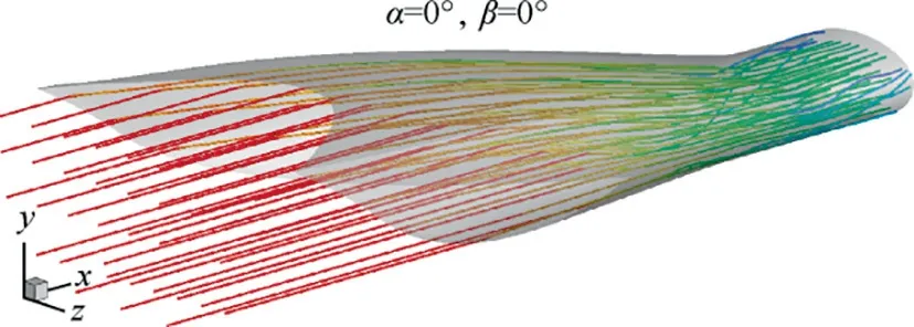
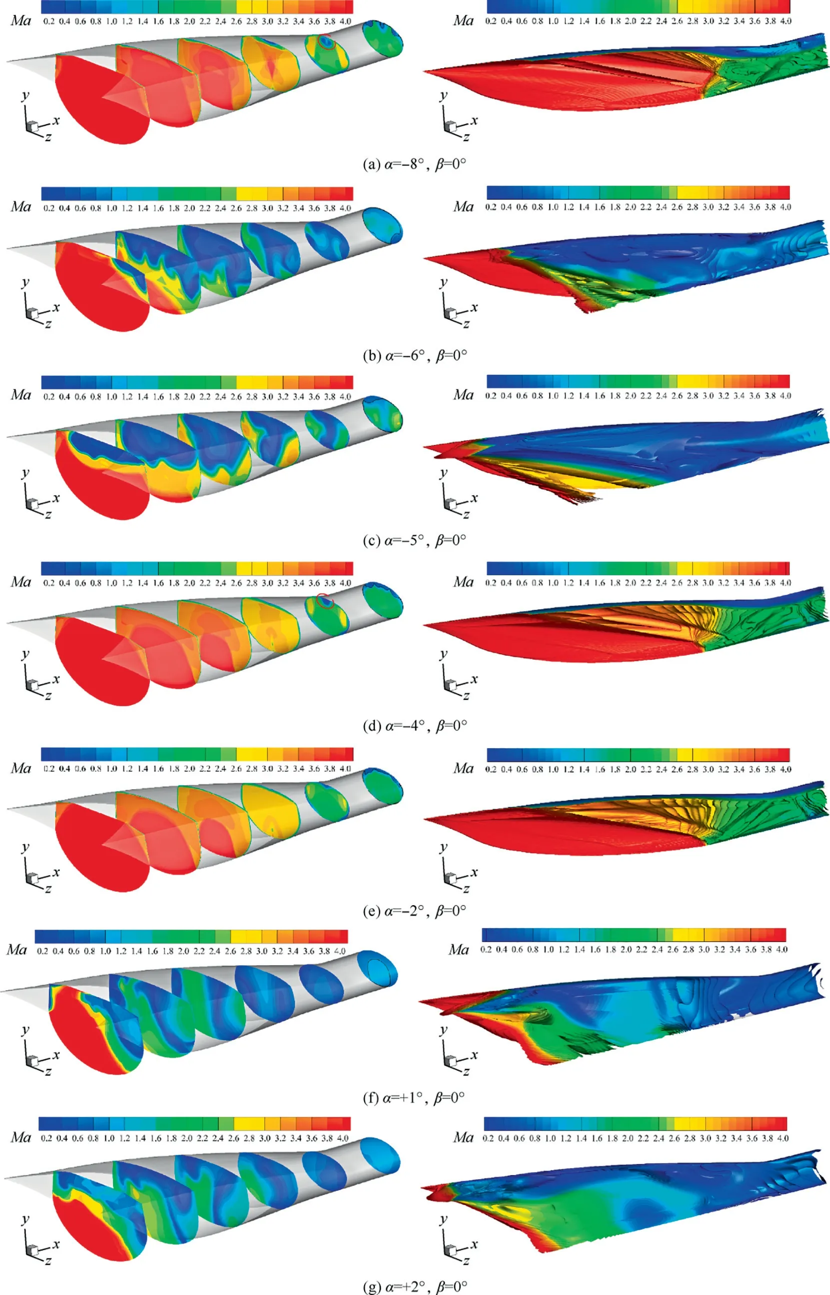
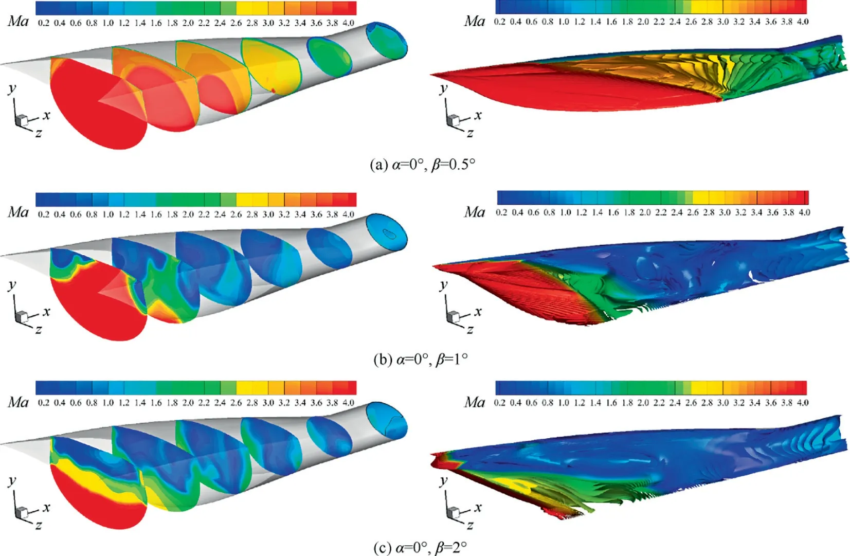
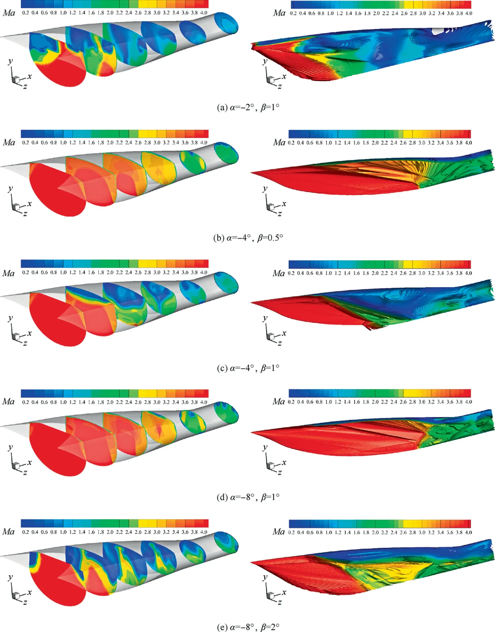
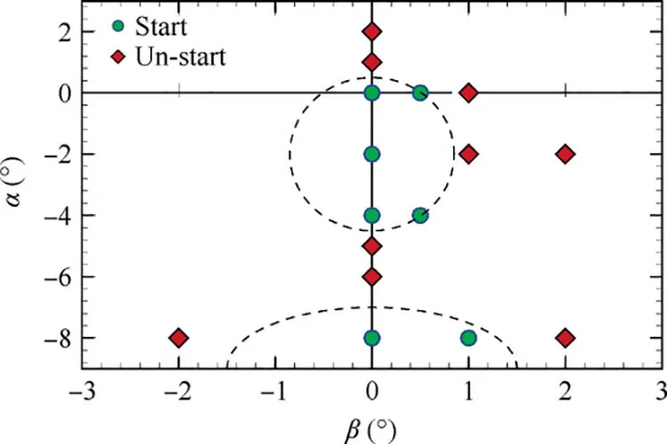
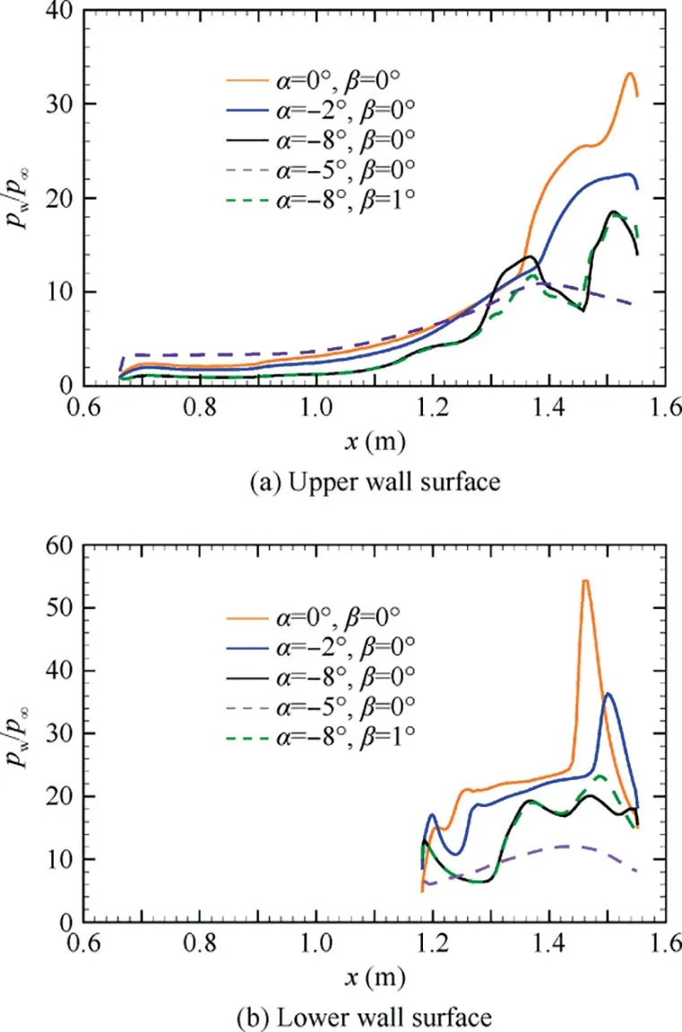
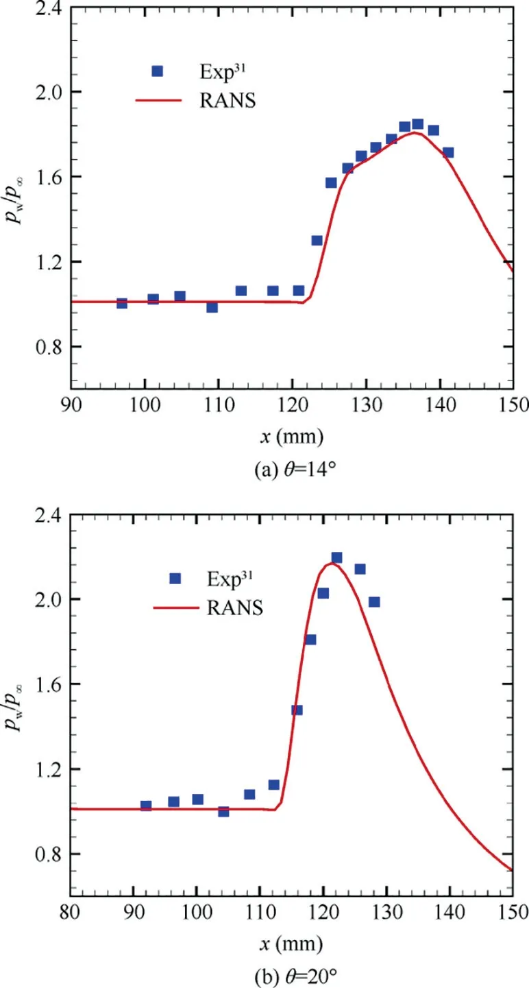
Fig. 8 Streamlines in started intake, and colored with local Mach number, 0.2 Fig. 9 Side view of MBus intake showing shock positions at angles of attack(two-dimensional schematic of wavecatcher intake at conditions of positive and negative attack angles). The contours of Mach number numbers in symmetry plane of the Ma=4.0 wavecatcher intake, before throat section, at various attack angles are shown in Fig. 10. At α=-2° and β=0° the incident shock is curved near the lower wall, indicating that the original parent flowfield is modified. Comparing with Figs. 8 and 10(a), the shock wave/turbulent boundary layer interaction near the throat section has decreased. Performance of wavecatcher intakes does not deteriorate severely at small negative angles of attack. At α=-4° and β=0°, a streamwise vortex is observed,which sharply increases the thickness of the boundary layer.This is shown with red dashed lines in Fig. 10(d). The vortex is caused by the normal velocity component, as the airflow on the upper wall surface develops downstream, forming a low-pressure zone, which evolves into a streamwise vortex structure. The streamwise vortex greatly decreases the flow area, adversely affecting the starting ability of the intake. At α=-5° and -6°, the intake becomes unstarted due to the thickened shear layer that is induced by the streamwise vortex.The three-dimensional streamlines of the unstarted intake are shown in Fig. 11. A strong shock is located in front of the intake lip, and a large amount of airflow is spilled out due to the detached shock.A separation region forms in the channel.In summary, at these negative angles of attack, the thickened shear layer poses a challenge to the startability of the intake. At α=-8°and β=0°,the intake re-starts,due mainly to the expansion fan formed at the leading edge, which increases the Mach number.These expansion fans affect the shock structures. At the end of the expansion fans, a separated shock is formed by the separation bubble and the transmitted shock,reflected by the lower wall surface,merges with the separation shock. Finally, a structure, with four intersecting shocks, is formed. The intersection point is located in the middle of the flow field, so that the position of the incident shock, on the upper wall, is moved forward, thereby alleviating the shock interaction on the shoulder.Moreover,the enlarged shear mixing layer still appears along the upper wall surface.These coupled factors cause the intake to re-start at α=-8°,β=0°.At the throat section,the shear mixing layer accounts for 30%of the channel height. In summary, the intake experiences a started-unstarted-started process with an increasing negative angle of attack. However, at positive attack angles, the intake stays in an unstarted mode. Fig.10 Streamwise distributions and iso-surfaces of Mach numbers of wavecatcher intake at various angles of attack(the black lines in left figures represent local sonic lines at the throat section). Fig. 11 Streamlines in started and unstarted intake, and colored with local Mach number. The mass averaged performance of a wavecatcher intake at different attack angles is reported in Table 1. At unstarted mode, due to the separation bubble, the aerodynamic throat section location is unknown, so the data is given only for a nominal geometric throat section. The same applies to Tables 2 and 3. A two-dimensional schematic of wavecatcher intake,at conditions of positive and negative attack angles is shown in Fig.12.With an increasing negative attack angle,the intake experiences a started-unstarted-started process.The total pressure recovery σtat the geometric throat section ranges from 0.2-0.8, and the static pressure ratio πtranges from 8-28. The wavecatcher intake is contracted by the side-wall surface,so the effect of sideslip angle is similar to that of positive attack angle. The intake will start at a very small sideslip angle,namely at α=0°,β=0.5°.While at β=1°,the intake transfers into an unstarted mode.In the unstarted mode,a detached shock is observed before the leading lip in Fig.13,and a large separation bubble is formed in the internal channel.Unstarting is easily triggered by a small sideslip angle. The data in the nominal throat section at different sideslip angles is shown in Table 2.The Ma3and total pressure recovery σ vs sideslip angle of the intake are shown in Fig.14.In the unstarted mode, the total pressure recovery decrease to 0.2–0.3, and the static pressure ratio of intake drops by a factor of three. Table 3 Mass averaged performance of wavecatcher intake at nominal geometric throat section at various angle of attack and sideslip angles. Fig. 12 Ma3 and σ vs α of intake at different conditions of angles of attack. Fig.13 Flow fields of wavecatcher intake at different conditions of sideslip angle(the black lines in left figures represent local sonic line at the throat section). Fig. 14 Ma3 and σ vs β of intake at different conditions of sideslip angles. The coupled effect of attack and sideslip angle is considered in this subsection. The thee-dimensional Mach number number distributions are shown in Fig.15 for different attack and sideslip angles. The intake can start at α=-4°, β=0.5° and α=-8°,β=1°.The started flow is similar to those in Figs.10 and 13. At the unstarted condition, an asymmetric detached shock is formed in front of the lip of the intake,causing a large amount of spillage. The main performance parameters at the throat section are summarized in Table 3. At conditions of attack and sideslip angle,the flow capture coefficient is always above 0.72 for a started intake. The total pressure recovery stays above 0.76 at the geometric throat section. The Mach number number is compressed to between 1.55 and 1.93.Although the wavecatcher intakes are totally traced according to the requirements of design-state parameters, the flow structures inside the intake closely follows the design characteristics at various off-design conditions with an overall highperformance. The morphed wavecatcher intake captures incoming flow in a variety of off-design states.For hypersonic propulsion systems, the thrust is proportional to the captured mass flow. Therefore, the high airflow capture capability at various angles of attack and sideslip is one of the virtues of the wavecatcher intake. Fig. 15 Flowfields of wavecatcher intake at different conditions of angle of attack and sideslip angle (the black lines in left figures represent local sonic line at the throat section). Fig.16 All simulated cases with attack angle on vertical axis and sideslip angle on horizontal axis. Fig. 17 Distributions of upper and lower wall-surface pressure in symmetry plane at various attack angles and sideslip angles. All simulated cases with attack angle on the vertical axis and sideslip angle on the horizontal axis are shown in Fig. 16. The green circle points represent started mode, the red points represent unstarted mode.At negative attack angle,the intake can start with a small sideslip angle. The dashed curves indicate the approximate startability boundaries. The wall-surface pressure in the symmetry plane of started intake are shown in Fig. 17. At α=0° and β=0°, the pressure attains its maximum value pw/p∞=54 at x ≈1.47m on the lower surface. Corresponding to Fig. 7, the secondary shock wave/turbulent boundary layer interaction forms in this region, leading to a sharp increment of pressure. At α=-8°and β=1°, the wall-surface pressure decreases rapidly, in the range of x=1.35–1.45 m, due to the shear mixing layer(shown in).Comparing with the effect of attach angle,the area where sideslip affects the pressure distributions of upper and lower wall surface is relative small. The off-design performance of a morphed MBus intake was investigated at Mach number 4.0. The MBus intake unstarts at a sideslip angle of 2°, a positive angle of attack of 1°. The positive attack angle has an adverse effect on the starting ability of the MBus intake.With the increase of the positive angle,the initial deflection angle of the airflow increases, that is, the strength of shock compression increases, which is not conducive to startability. The effect of sideslip angle is somewhat similar to positive attack angle. At negative angles, there are two features that govern startability. As the negative angle of attack increases, the initial deflection angle of airflow decreases.The shock wave compression is weakened, which is conducive to intake starting.However, the formation of the secondary shock aggravates the interaction with the thick boundary layer along the upper wall. It induces the formation of a large streamwise shear layer, adversely affecting startability. The CFD results show that the MBus intake unstarts at α=-5°due to the thickened shear layer. Then it re-starts at α=-8°, with a re-formed shock structure, mainly due to the expansion fan formed at the leading edge. The intake experiences a started-unstartedstarted process at negative attack angles. Coupled with negative attack angle, the wavecatcher intake can start at conditions of sideslip. Acknowledgements F-Y. Zuo would like to acknowledge the support of National Natural Science Foundation of China (No.: 12002261);National Postdoctoral Program for Innovative Talents of China (No.: BX20200267); Young Talent fund of University Association for Science and Technology in Shaanxi of China(No.: 20200501); China Postdoctoral Science Foundation(No.: 2020M673411); the Fundamental Research Funds for the Central Universities of China (No.: xzy012020096).G. Chen are grateful for the support of National Natural Science Foundation of China (No.: 11872293). Appendix A. Assessment of turbulence model The Realizable k-ε model was proposed to improve the standard k-ε eddy viscosity model,consists of a new model dissipation rate equation and a new eddy viscosity formulation. The new model dissipation rate equation is based on the dynamic equation of the mean-square vorticity fluctuation at large turbulent Reynolds number. The new eddy viscosity formulation is based on the realizability constraints: the positivity of normal Reynolds stresses and the Schwarz’s inequality satisfaction for turbulent shear stresses.30 The adopted turbulence model is assessed by comparing with experimental data. The flow condition follow the experimental parameters with Ref. 31 as much as possible with a free-stream Mach number 2.0, to assess Realizable k-ε turbulence model in high-Reynolds-number flow. The domain is chosen with streamwise length Lx=300mm, height Ly=60mm, width Lz=120mm. The distance between the cone axis and the flat surface is set as h=30mm.The opening semi-cone angle is changed with different values to control the conical shock intensity, namely 14°, 20°. Based on the experimental results,the flow with θ=14◦has no separation.at condition of θ=20◦corresponds to a separation. So the chosen parameters of opening semi-cone angle has a wide range for comprehensive verification of turbulence model. The grid points are clustered towards the bottom wall, in such a way that the first point has a distance y+≈1, for all cases. Fig. A1 Distributions of wall pressure in the symmetry plane with different semi-cone angles. An important feature in shock/boundary layer interactions is the wall pressure load,which may have important impact on the behavior of the underlying structural components. The mean wall pressure pwacross the interaction zone in the symmetry plane with different semi-cone angles is compared in Fig. A1 with the experimental data.31The figure well brings out the N-wave wall signature of the conical shock, with pressure rising sharply at the nominal shock impingement location,then decreasing almost linearly. Based on the comparison reported in Fig. A1, we can confidently conclude that the RANS results adequately capture the mean flow features.

4.3. Performance at sideslip angle



4.4. Performance at α and β
5. Conclusions
 CHINESE JOURNAL OF AERONAUTICS2021年7期
- CHINESE JOURNAL OF AERONAUTICS的其它文章
- Integrated batteries layout and structural topology optimization for a solar-powered drone
- Polynomial networks based adaptive attitude tracking control for NSVs with input constraints and stochastic noises
- Morphing wing flaps for large civil aircraft:Evolution of a smart technology across the Clean Sky program
- Review on bio-inspired flight systems and bionic aerodynamics
- SARISTU:Adaptive Trailing Edge Device(ATED)design process review
- Continuous morphing trailing-edge wing concept based on multi-stable nanomaterial
