A study of morphing aircraft on morphing rules along trajectory
Xioyu CHEN, Chunn LI, Chunlin GONG,*, Lingxin GU,Andre D RONCH
a Shaanxi Aerospace Flight Vehicle Design Key Laboratory, School of Astronautics, Northwestern Polytechnical University,Xi’an 710072, China
b University of Southampton, Southampton SO17 1BJ, United Kingdom
KEYWORDS Aerodynamic;Morphing wing;Multi-fidelity Kriging model;Offline optimization;Trajectory planning
Abstract Morphing aircraft can meet requirements of multi-mission during the whole flight due to changingthe aerodynamic shape,soit isnecessary tostudyits morphingrules along the trajectory.However, trajectory planning considering morphing variables requires a huge number of expensive CFD computations due to the morphing in view of aerodynamic performance. Under the given missions and trajectory,to alleviate computational cost and improve trajectory-planning efficiency for morphing aircraft,an offline optimization method is proposed based on Multi-Fidelity Kriging(MFK)modeling.The angle of attack,Mach number,sweep angle and axial position of the morphing wing are defined as variables for generating training data for building the MFK models,in which many inviscid aerodynamic solutions are used as low-fidelity data,while the less high-fidelity data are obtained by solving viscous flow.Then the built MFK models of the lift,drag and pressure centre at the different angles of attack and Mach numbers are used to predict the aerodynamic performance of the morphing aircraft,which keeps the optimal sweep angle and axial position of the wing during trajectory planning.Hence,the morphing rules can becorrespondinglyacquiredalong the trajectory,as well as keepthe aircraft with the bestaerodynamic performanceduringthe wholetask.The trajectoryplanningofamorphingaircraft was performed with the optimal aerodynamic performance based on the MFK models,built by only using 240 low-fidelity data and 110 high-fidelity data. The results indicate that a complex trajectory can take advantage of morphing rules in keeping good aerodynamic performance,and the proposed method is more efficient than trajectory optimization by reducing 86%of the computing time.
1. Introduction
An aircraft with morphing wing can actively change the sweep angle and/or the position of the wing during flight,1–3and the wing shape or the profile of the wing will change accordingly,so that the aircraft can maintain good aerodynamic performance during the whole trajectory under the given flight missions4Compared with fixed-wing aircraft, morphing aircraft has many advantages, for example, it can adapt to a wide range of speed and airspacem5NASA analyzed the morphing swept wing aircraft at transonic speed, and obtained the morphing rules of changing sweep angle,6which only considered the aerodynamic characteristics. Ref. 7 presented the results obtained from the numerical simulations and experimental wind tunnel tests of a morphing wing, which can benefit the research of morphing rules. Refs. 8,9 studied the morphing wing in reducing drag through optimization and design of the wing. Ref. 10 investigated the transient aeroelastic responses of a variable-span wing. Zhang et al. and Chen et al. studied the aerodynamic characteristics of the morphing swept wing and the variable span wing, and proposed a method to improve the lift and drag characteristics of the missile during the flight,11–13but the trajectory was not considered in their study. The greatest difficulty is that the change of the sweep angle and/or the position of the wing make(s) the dynamic design of the flight and the trajectory characteristics of aircraft more complicated,especially for studying morphing rules along the trajectory.14
To obtain the morphing rules along the trajectory of a morphing aircraft, trajectory optimization is commonly used,15which can be classified as indirect methods and direct methods.16,17The indirect methods are sensitive to the initial value,which make the problem difficult to solve.The direct methods include the shooting method,the Particle Swarm Optimization(PSO), the collocation method and so on. The shooting method only discretizes control variables and can obtain high precision solutions with less optimization parameters. But as the number of discrete points increases, the scale of nonlinear programming increases sharply, so that the convergence time of the shooting method is very long.18,19The PSO is an evolutionary algorithm based on swarm intelligence. It is easy to implement and search globally.20In Refs. 21–23, the optimal control method is combined with the PSO to study the relationship between the range augmenting capability and the launching conditions of the morphing swept aircraft.However,like other global optimization algorithms, the PSO has low convergence accuracy and slow convergence rate.The collocation methods discretize control variables and state variables,including the Pseudo-spectral Method (PM), the Hermit-Simpson method, the Runge-Kutta method and the Euler method. Among those methods, the PM, including Guass pseudo-spectral method,24Legendre pseudo-spectral method and Radau Pseudo-spectral Method (RPM), is the most popular one of the coordination point method.25Huang et al.14and Zhao and Sun26used the RPM to solve the trajectory optimization problems of the morphing wing aircraft. For simple and less-constrained problems, the RPM can quickly obtain the ideal solution; but for complex problems, the RPM needs higher-dimensional interpolation polynomials to obtain an approximate solution. Besides, the RPM is highly dependent on constraints when used to solve trajectory optimization problems.
In this paper,an efficient offline trajectory planning method is proposed for studying the morphing rules of morphing aircraft, by which the study of the morphing rules is turned into a simple optimization problem and a trajectory design problem, different from the usual optimal control problem. First,the morphing forms and the trajectory planning problem are presented. Then, the efficient method for planning the trajectory to obtain the morphing rules is introduced, including the procedure of planning trajectory and the Multi-Fidelity Kriging(MFK)modeling method.Finally,the morphing rules of a certain morphing aircraft are studied by the proposed method, and the results are presented and discussed.
2. Problem description
To manage an assumed task including cruising,patrolling and penetrating, which needs to take account both low- and highvelocity performance, a morphing wing that can change its sweep angle and axial position is implemented. Since the trajectory of the morphing aircraft is determined by flight missions, the trajectory profile of the assumed given missions is shown in Fig. 1.
The aircraft takes off from the ground with a low initial velocity and then climbs up to the cruising height.After cruising, it slows down and descends to the patrolling height. Following patrolling, it accelerates and descends for penetrating.According to the missions of the flight, the requirements for the trajectory planning are assumed as follows:(A)total cruising time should be larger than 40 min; (B) the total flight distance should be no less than 1000 km;(C)the cruising height is higher than 14 km, and the cruising velocity should be no less than 0.9 Ma; (D) the patrolling height should be no higher than 3 km,and the patrolling velocity should be no larger than 0.35 Ma;(E)the penetrating height is 0.1 km and the penetrating velocity is 0.8 Ma. Hence, the main flight trajectory assumed to be planned can be divided into three main segments: the stage of acceleration in climbing for cruising; the stage of deceleration in descent for patrolling; the stage of acceleration in descent for penetrating.
To alleviate the shock drag, a supercritical airfoil is chosen from the NACA series. Considering the structure strength, the sweep angle is limited by 43°; in view of the longitudinal stability, the forward and backward movement of the wing are limited to 365 mm. The body of the aircraft is not the focus of our study, hence a simple body shape was chosen. The wing changes its shape by shear deformation, so the airfoil is always the same and parallel to the incoming flow. Besides, the wing can move along x-axis of the body.In order to obtain a reasonable static stability of the aircraft,when the sweep angle increases, the wings move forward,and vice versa. The top views of the shapes in limited morphing positions are shown in Fig. 2, with the minimum sweep angle and the maximum sweep angle. The aerodynamic shape and the flight mission of this aircraft are referred to AGM-158 airfield missile,27in which the connection between the wing and body is simplified and the wing is directly inserted into the fuselage just on the bottom of the body.
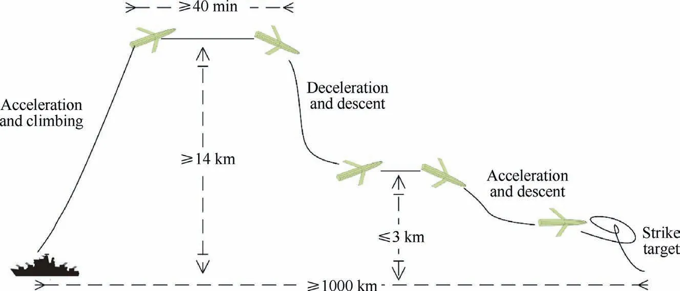
Fig. 1 Demonstration of trajectory profile.
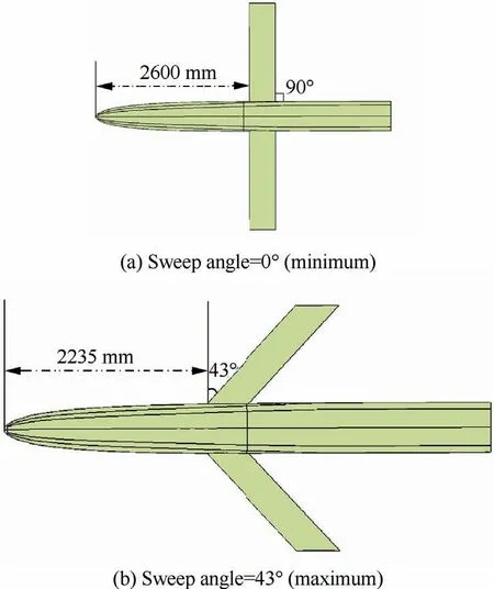
Fig. 2 Top views of aircraft in limited morphing positions.
3. Methods
3.1. Method of studying morphing rules along trajectory
During trajectory planning, aerodynamic forces need to be computed to provide inputs for solving trajectory equations iteratively.However,for morphing aircraft,due to the morphing of the wing in its shape and position, a huge amount of CFD simulations are needed, which is unbearable. In our work, surrogate models of aerodynamic forces and pressure centre are used in lieu of expensive CFD simulations. To further improve the efficiency for trajectory planning,many inviscid aerodynamic simulations are performed to obtain lowfidelity data, and few viscous solutions are obtained as highfidelity data. Since the influence of boundary layer is not considered in inviscid aerodynamic simulations, the mesh amount is much less than that of viscous simulations, which greatly reduces the time for inviscid CFD simulations. Then the MFK models are built and the cross-validations are performed to ensure model accuracy. Thereafter, the built MFK models are used to generate optimal inputs for trajectory planning,which will keep the best aerodynamic performance through changing the sweep angle and the axial position of the wing.Finally, according to the planned trajectory, the morphing rules can be obtained. The whole flowchart for learning the morphing rules along the trajectory is depicted in Fig. 3.
In the whole process, MFK modeling is the most critical step. This model is cheap to be built by using quite few highfidelity data, and shows small approximation error. In the study of the morphing rules of morphing aircraft, usually a huge number of high-fidelity CFD analyses are needed in trajectory planning. Even by using surrogate models, many expensive viscous CFD analyses are still necessary.In our current study,only few viscous data are available considering the computational expense. Thus, the MFK modeling is a good choice, as it can take a good advantage of few high-fidelity data and more low-fidelity data,and build a relatively accurate model.
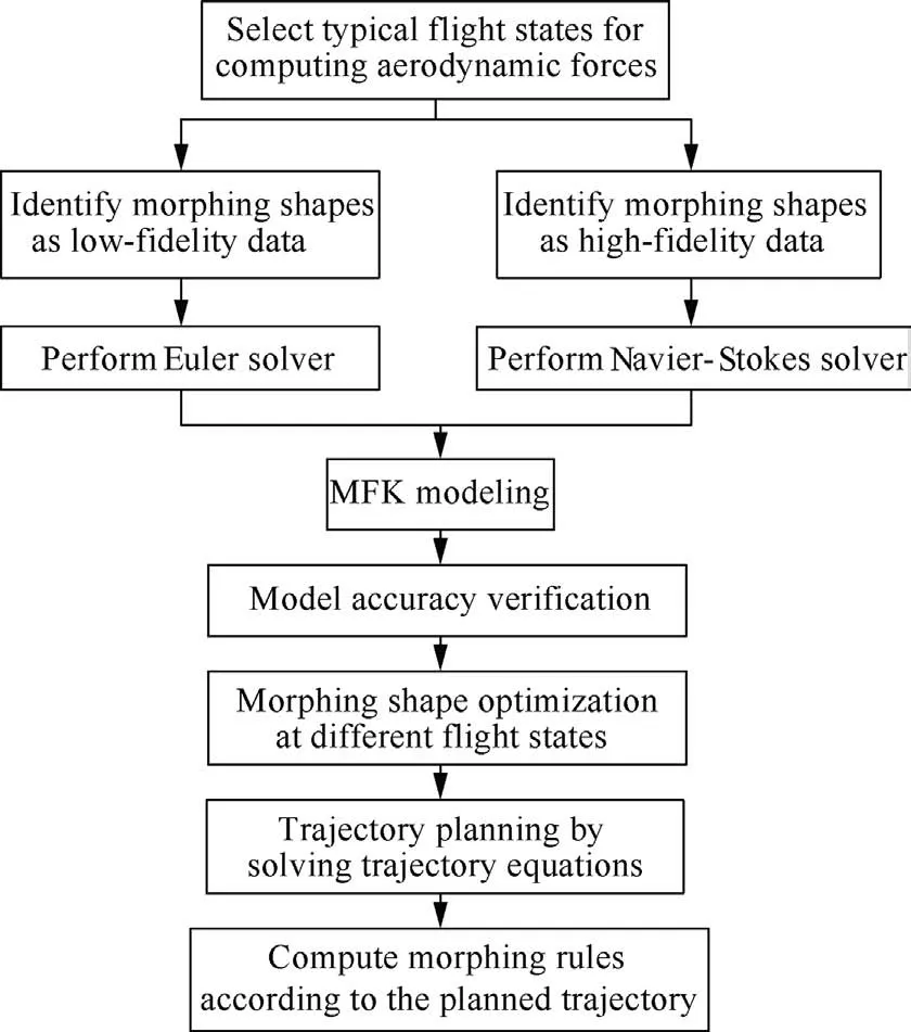
Fig. 3 Flowchart for studying morphing rules along the trajectory.
3.2. Dynamic model
Based on the assumption of instantaneous equilibrium, the morphing aircraft is regarded as a controllable particle, and thus only the motion of the mass centre in the longitudinal plane is studied. The trajectory equations are written as

in which m is the mass of the aircraft; v, α, θ are respectively the velocity, the angle of attack and the trajectory inclination angle of the aircraft;P,X,Y are respectively the engine thrust,the drag and the lift; msis the mass flow rate. Usually, the aerodynamic forces are obtained from CFD simulations,which are performed by using commercial software or inhouse code. Since the propulsion of the engine changes,another two equations are needed to enclose the above dynamic model, which are written as

in which ε1is the control equation of the angle of attack, ε2is the engine speed control equation, and n is the engine speed.
3.3. Multi-fidelity Kriging model
Surrogate model can effectively reduce the computational burden in solving complex problems,28but for real applications,even surrogate modeling based on high-fidelity data also needs unbearable computation resources. However, variable-fidelity model provides an opportunity to further ease the computational burden.29–34The surrogate model used in the paper is the Multi-Fidelity Kriging (MFK)model using an autoregressive model of first order,35,36which is similar to the hierarchical Kriging.37–39
The reasons for choosing the MFK model are as follows:(A)it can be built by using few high-fidelity data and a certain amount of low-fidelity data,which can save a lot of expense on CFD analyses; (B) it takes the low-fidelity model as a global prediction of the problem,which can avoid computing covariance matrix in the co-Kriging modeling; (C) it can reduce dimension of the matrix for building the surrogate, which can improve the efficiency of fitting surrogates; (D) it brings error prediction to the low-fidelity model,which can greatly improve model accuracy if the trend of the low-fidelity model is correct.
As only two sets of data in high- and low-fidelity are used,the MFK model can be simplified as

in which ρ(x ) is the scaling or correlation factor between the low- and high-fidelity data, which can be a constant, a linear function or a quadratic function; δ(x )is the discrepancy function; ylow(x ) and yhigh(x ) are respectively surrogate models built by low- and high-fidelity data. Here, the Kriging model is chosen for building the surrogates ylow(x ) and yhigh(x ), as it can well approximate nonlinear problems and simultaneously provide predicted error of the model. Details of theory for building Kriging model can be found in Refs. 40,41. In fact, δ(x ) is a Gaussian process independent of ylow(x ). The correlation degree and the scale factor ρ(x ) between ylow(x )and yhigh(x ) can be computed by

in which Cov[yhigh, ylow] is the covariance between the lowand high-fidelity model; Var[ylow] is the variance of the lowfidelity model.Using Kriging model can profit computing variance and covariance.
3.4. Leave-one-out cross validation
Cross validation, sometimes called rotation estimation, is a practical method to cut data set into smaller subsets in statistics in order to evaluate the predictive performance of the model, which is proposed by Seymour Geisser. Cross validation can avoid overfitting to some extent and make full use of the data for training and verification. The basic idea of cross-validation is as follows:in a given data set,most samples are taken out to build the model while the left samples are used for prediction by using the built model, and then the sum of prediction error of those left samples is calculated and used to verify the accuracy of the model.
Leave-one-out cross validation is one type of cross validation methods.It is suitable for small size of samples.Assuming that there are n samples in the data set, the basic idea of leaving-one-out cross validation is to treat each sample as a separate test set and the remaining n-1 samples as a training set, so that only one sample in each turn is not used for training the model but for verification. In addition, in the experiment, there is no random of the experimental data to ensure that the experimental process can be replicated.
The root-mean-square error and the relative root-meansquare error are used to evaluate model accuracy, the expressions of which are as follows:
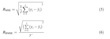
in which l is the number of samples; yiand ^yiare the true and predicted values, respectively; y- is the average of yi.
3.5. Morphing shape optimization in different flight states
Based on the MFK models, optimizations can be performed,subject to limitations of the sweep angle, the axial position of the wing and the longitudinal pressure centre, to obtain optimum shapes with maximum lift-to-drag ratios. The mathematical expression of the optimization problem is defined as

in which J is the objective function representing the lift-to-drag ratio, which is calculated by the MFK models; χ is the sweep angle, and χlimitis the limitation of the sweep angle; xarepresents the axial position of the wing;xa,lowand xa,upare respectively the lower and the upper limitation of the axial position of the wing; xpis the longitudinal pressure centre; xp,lowand xp,upare the lower and the upper limitation of the longitudinal pressure centre, respectively. Then an interpolation table for the optimum aerodynamic performance can be established,which can be used for planning trajectory.
4. Results and discussion
4.1. Results of aerodynamic performance simulation
To build the MFK models, flight states about the Mach number and the angle of attack should be specially chosen with respect to flight envelop.In our work,the Mach numbers chosen are{0.35,0.5,0.65,0.8,0.95},the angles of attack specified are{0°,2°,4°,6°,8°},and thus there are totally 25 flight states.For each state, considering the limitation of the sweep angle and the axial position of the wing, as well as the aerodynamic performance of the swept wing, different shapes are selected for performing low- and high-fidelity CFD computations.The commercial software Fluent is used for CFD computations, where the Euler solver is used for obtaining lowfidelity data, while the Navier-Stokes (N-S) solver combined with Spalart-Allmaras turbulent equation is taken for computing high-fidelity data.Fig.4 shows the surface mesh of the aircraft, which is the unstructured mesh, and the size of the meshes on the head and wings is small. Details of the meshes on the symmetrical plane, the structured/unstructured hybrid meshes in the space and the meshes in the boundary layer are respectively shown in Figs.5–7.The height of the first layer of the structured/unstructured mesh is 0.05 mm.
4.2. Results of MFK modeling
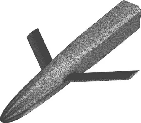
Fig. 4 Surface mesh.
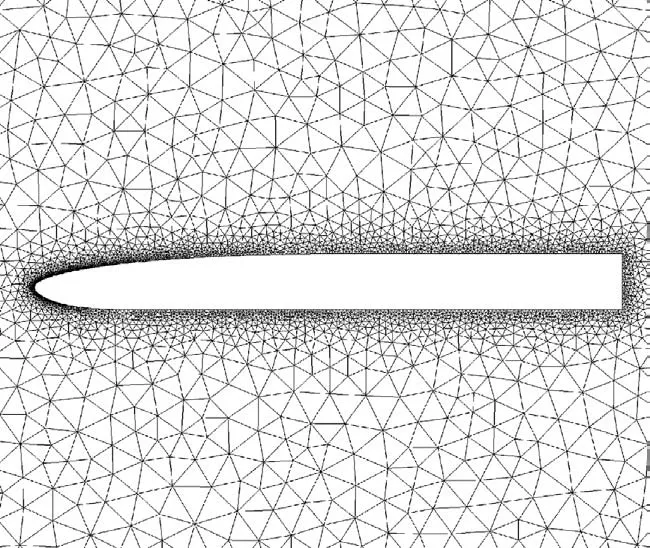
Fig. 5 Symmetrical plane of unstructured mesh.
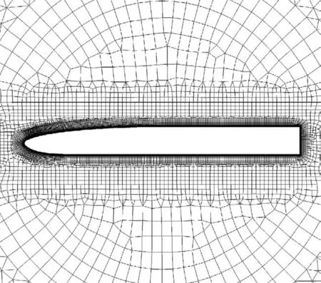
Fig. 6 Symmetrical plane of structured/unstructured hybrid mesh.
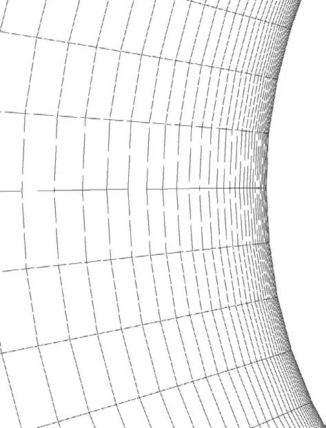
Fig. 7 Zoomed-in boundary layer around the head.
Totally, 240 morphing shapes are selected for obtaining lowfidelity data,while 110 morphing shapes are chosen for obtaining high-fidelity data. Obviously, χ=0◦is best for 0.35 Ma,χ = 43◦is best for 0.95 Ma, and thus only axial positions of the wing are considered in those two cases. Considering the limitations of the pressure centre, the wing should be respectively at the rearmost end and the forefront of the movable range at 0.35 Ma and 0.95 Ma, so the aerodynamic shapes are determined and no model is built at those two Mach numbers. For other flight states, three MFK models are built at each state respectively for the lift coefficient, the drag coefficient and the pressure centre. The lift-to-drag is not modeled but calculated using the models of lift coefficient and drag coefficient. The open-source Surrogate Modeling Toolbox(SMT) is employed42.
After building the MFK models, leave-one-out cross validation is taken to verify the accuracy of the models. Since the aerodynamic characteristics of each flight state are similar to some extent, only model accuracy verification of a certain flight state is needed.The leave-one-out cross validations were performed for all the flight states to verify the model accuracy of the lift coefficient,the drag coefficient and the pressure centre.The evaluation indexes RMSEand RRMSEof different flight states are shown in Table 1 and Table 2,respectively.As far as engineering application is concerned, it is obvious that the MFK models have sufficient precision because of the small RMSEand RRMSE.
4.3. Results of optimization
After building those MFK modes, optimization problems, as shown in Eq. (7), are performed to obtain optimum shapes with maximum lift-to-drag ratios based on the built MFK models. The limitation of the sweep angle, the axial position and the pressure centre are respectively [0°, 43°], [2235 mm,2600 mm]and[2760 mm,2920 mm].The morphing parameters of the optimum shapes for each flight state are shown in Table 3, in which the first parameter in parentheses is the sweep angle, and the second parameter is the axial position of the wing.
The specific optimum aerodynamic shapes for each flight state are shown in Fig.8,in which the repeated shape in Table 3 is shown only once. According to the optimum shapes, interpolation tables for the optimum aerodynamic performance are established, as shown in Table 4 and Table 5, which can be used for trajectory planning.
4.4. Morphing rules along trajectory
Based on the aerodynamic performance from Table 4 and Table 5,the trajectory planning of the morphing aircraft is performed. The main flight stages are analysed below. Among all the flight stage, the cruising and patrolling maintain constant height, thus their trajectories are straight lines, and the flight distances are determined by fuel consumption.The initial state point for the trajectory planning is known,with height of 0 km and velocity of 0.2 Ma. Then the aircraft climbs up to the cruising height of 15 km, with a distance of 272 km, which can be seen in Fig.9.After cruising 270 km,the aircraft begins to descend for patrolling, and the distance for the descending stage is 275 km. After patrolling for 415 km, the aircraft descends further but speeds up to reach penetrating velocity.The total distance that the aircraft travels is 1290 km.
(1) Acceleration and climbing stage
The goal of the acceleration and climbing stage is to achieve the cruising height and velocity, and thus the angle of attack and the speed of the engine should be large in order to provide enough lift and thrust. The initial mass of the aircraft is specified as 1000 kg.As shown in Fig.10 and Fig.11,during climbing to an altitude of 15 km,the velocity increases from 0.2 Ma to 0.952 Ma, which meets the requirements of cruising. The trajectory rises gradually,and the mass of the climbing section reduces to 911 kg at its end state point. Accordingly, the morphing rules of the sweep angle and the axial position of the wing can be obtained, as shown in Fig. 12(a) and (b). It can be seen that the sweep angle of the aircraft begins to increase at about 0.35 Ma, increases faster from 0.5 Ma, and finally reaches 43° with the velocity of 0.95 Ma. However the axial position of the wing keeps unchanged until 0.5 Ma, when the wing starts to move forward. Ultimately, the wing moves to the lower limitation of the axial position.
(2) Deceleration and descent stage
After 16 min cruising, the mass of the aircraft reduces 61 kg, and the aircraft begins to descend, so the initial mass of the trajectory in this section is 850 kg.In this trajectory section,the speed of the aircraft reduces fast as well as the height,so the angle of attack and the speed of the engine should not be too large to meet the requirements, which makes the fuel consumption small.The mass of the aircraft at the end of this trajectory section is 833 kg. During descent, the height reduces from 15 km to about 3 km, while the velocity decreases from 0.95 Ma to 0.35 Ma,as shown in Fig.13 and Fig.14.Accordingly,the sweep angle begins to reduce along with the deceleration; however the change rate slows down at about 0.5 Ma.The wing moves backward until reaching the upper limit of the axial position also at 0.5 Ma,which can be seen in Fig.15.
(3) Acceleration and descent stage
After one-hour patrolling, the aircraft enters the acceleration and descent stage, the initial mass of which is 750 kg.As shown in Fig. 16 and Fig. 17, in 330 s the aircraft rapidlydecreases and speeds up to prepare for penetration. Besides thrust,a rapid descent can also increase the velocity of the aircraft.Hence the fuel consumption is very small and the mass at the end of this stage is 739 kg. In Fig. 18, the changes of the sweep angle and the axial position of the wing via time are shown. It can be seen that along with acceleration, the sweep angle increases, but it does not reach the maximum sweep angle to keep better aerodynamic performance for trajectory planning. Accordingly, the wing moves forward and does not reach the minimum limitation of the wing position.

Table 1 RMSE of different flight states.

Table 2 RRMSE of different flight states.

Table 3 Morphing parameters of optimum shapes.
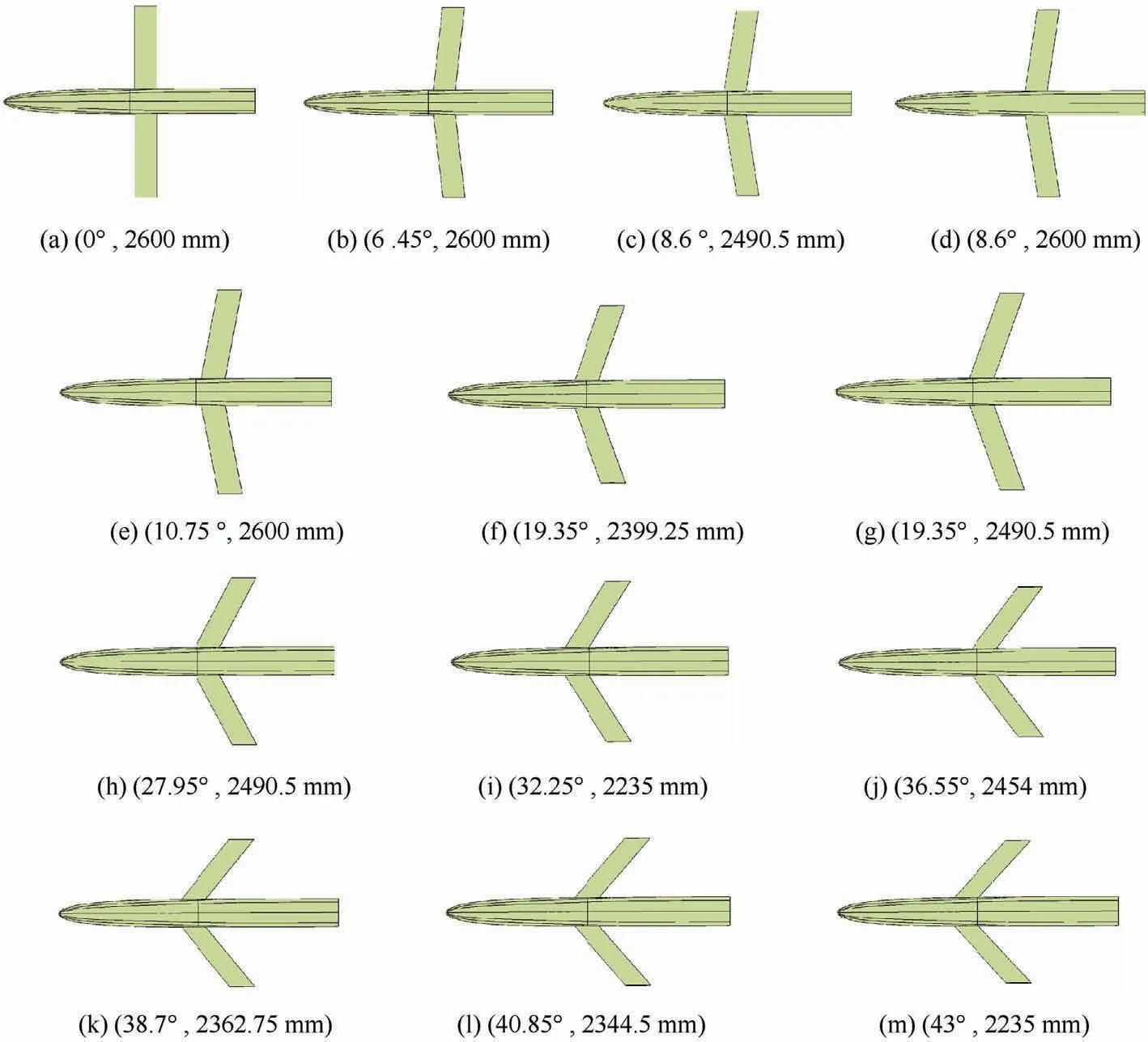
Fig. 8 Specific optimum aerodynamic shapes.

Table 4 Lift coefficients of optimum shapes.

Table 5 Drag coefficients of optimum shapes.
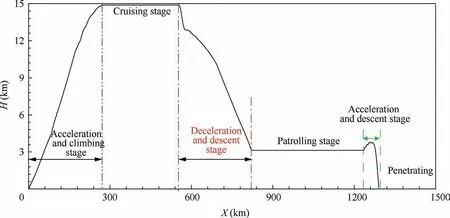
Fig. 9 Whole trajectory of the aircraft.
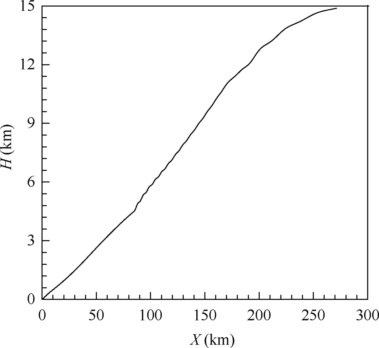
Fig. 10 Trajectory in acceleration and climbing stage.
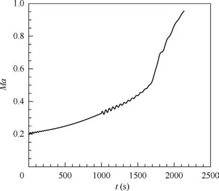
Fig. 11 Velocity curve in acceleration and climbing stage.
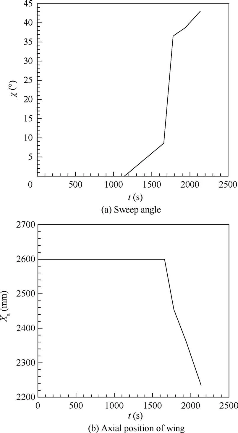
Fig. 12 Morphing rules for acceleration and climbing stage.
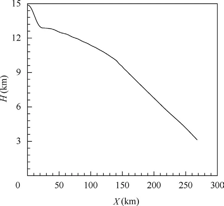
Fig. 13 Trajectory in deceleration and descent stage.
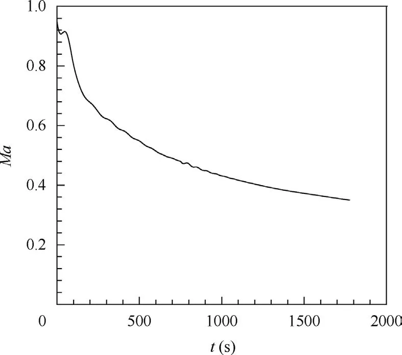
Fig. 14 Velocity variation in deceleration and descent stage.
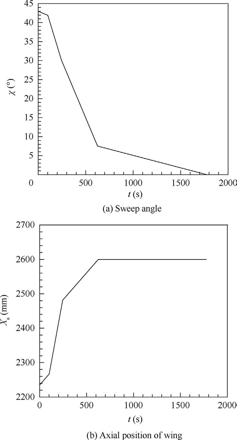
Fig. 15 Morphing rules of deceleration and descent stage.
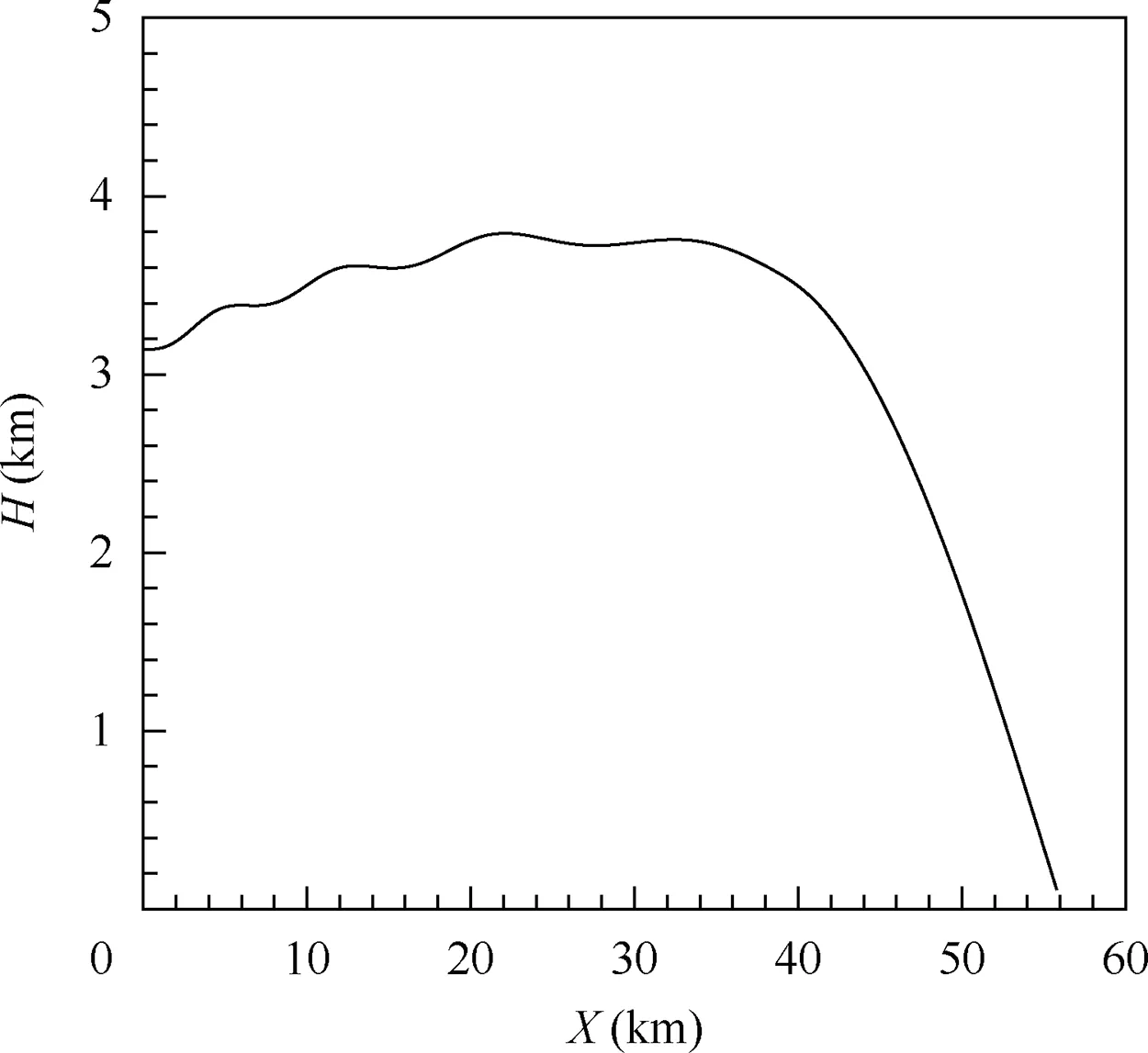
Fig. 16 Trajectory of acceleration and descent stage.
It is obvious that when the speed is low,between 0.2 Ma and 0.35 Ma,the aircraft is always in the optimal shape with sweep angle of 0°, while when the speed exceeds 0.35 Ma, the sweep angle starts to slowly increase to obtain an optimal shape,and the axial position of the wing begins to move forward accordingly. Between 0.65 Ma and 0.8 Ma, the sweep angle changes sharply,no matter in acceleration stage or deceleration stage.As shown in Fig.17 and Fig.18,in the acceleration and descent stage, when the speed increases from 0.65 Ma to 0.8 Ma, the optimal sweep angle changes from about 8.6° to 32.25°, not reaching the upper limitation. Generally, in each stage,the sweep angle as well as the axial position of the wing changes monotonously and continuously,which is suitable for manipulation with respect to structure organization.
In view of the efficiency, there are totally 240 low-fidelity data by the Euler solver and 110 high-fidelity data by the NS solver performed for trajectory planning. If the trajectory planning is carried out directly using high-fidelity data, it will take hundreds and thousands of high-fidelity computations. If the commonly used trajectory optimization is performed,such as the Radau pseudo spectral method,in order to obtain accurate aerodynamic interpolation table for the morphing aircraft,the angle of attack should be divided into 5 points;the velocity should be divided into 3 points,of which 0.35 Ma and 0.95 Ma need not to be calculated;the sweep angle and axial position of the wing should be respectively divided into 10 points at least.Normally,aerodynamic data for more flight states needs to be calculated by performing trajectory optimization. For our problem, it needs at least 1500 high-fidelity data to construct a complete four-variable aerodynamic interpolation table.Moreover,for some obvious unreasonable states,for example,the shape of the wing without sweep has to be simulated in transonic flight, so it costs more expensive computing resources. For the CFD simulations of the morphing aircraft,a low-fidelity simulation needs about 5 h while a high-fidelity simulation needs about 12 h by using a sixteen-thread computer.It takes 2520 h using the method proposed in this paper while it takes 18,000 h using the trajectory optimization,so it is obvious that the former can reduce 86% of computing time than the latter. The comparison of the computational states by the proposed method and trajectory optimization is shown in Table 6. It takes two more times of computational expense by directly performing trajectory optimization.Hence,the proposed method is more efficient in studying morphing rules.
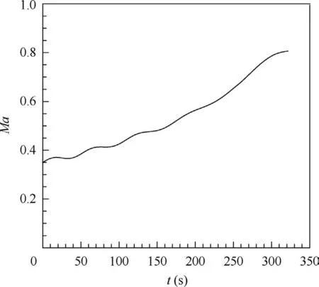
Fig.17 Velocity variation rule of acceleration and descent stage.
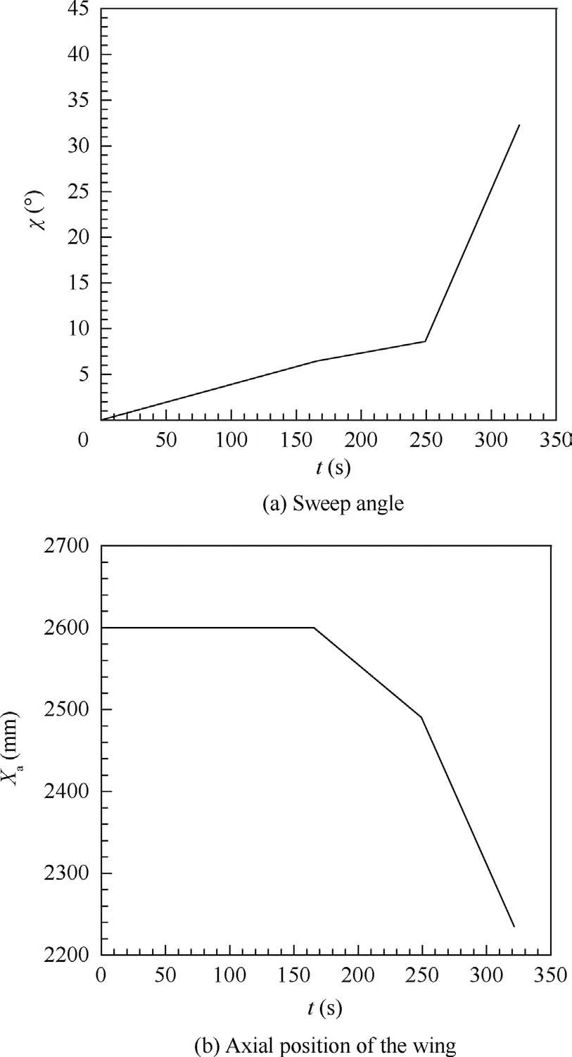
Fig. 18 Morphing rules of acceleration and descent stage.

Table 6 Comparison of computational states by using proposed method and trajectory optimization.
5. Conclusions
To avoid huge computational cost and improve the efficiency for studying morphing rules of a morphing aircraft along the trajectory, a method based on the MFK model is proposed.The flight states need to be specially chosen within the range of velocity and angle of attack, for which surrogates need to be built to obtain optimum shapes.Attention needs to be paid for the limitations of the morphing ranges,when selecting morphing shapes for computing low- and high-fidelity data. The MFK models are proved to be accurate for predicting aerodynamic performance by the leave-one-out cross validations.The results for studying the morphing rules of the aircraft which can change its sweep angle and axial position of the wing indicate:
(1) The computational cost can be greatly reduced by using the MFK model in comparison with traditional trajectory planning by reducing 86% of the computing time.
(2) The morphing of the aircraft along the trajectory is monotonous in each task stage,which demonstrates that morphing rules are suitable for structure organization.
(3) The proposed method provides a potentially-efficient way for studying morphing rules along trajectory of morphing aircraft.
MFK model is proposed to study the morphing rules of morphing aircraft.However,the morphing parts of the aircraft are mainly the wings, and there are not many variables involved. Since the proposed method is based on the MFK model,even with more morphing variables,the data increment needed for building the MFK models is more less than trajectory optimization. Thus, in the future, the morphing of the whole aircraft can be considered and the morphing parameters of the aircraft can be more for further study. Moreover, only one kind of the multi-fidelity model, MFK, is used in this paper, so other multi-fidelity models, such as the multifidelity model based on Radial Basis Function (RBF), can be studied and compared in the future.
Acknowledgements
This study was co-supported by the National Defense Fundamental Research Funds of China(No.JCKY2016204B102 and JCKY2016208C001).
 CHINESE JOURNAL OF AERONAUTICS2021年7期
- CHINESE JOURNAL OF AERONAUTICS的其它文章
- Integrated batteries layout and structural topology optimization for a solar-powered drone
- Polynomial networks based adaptive attitude tracking control for NSVs with input constraints and stochastic noises
- Morphing wing flaps for large civil aircraft:Evolution of a smart technology across the Clean Sky program
- Review on bio-inspired flight systems and bionic aerodynamics
- SARISTU:Adaptive Trailing Edge Device(ATED)design process review
- Continuous morphing trailing-edge wing concept based on multi-stable nanomaterial
