A review of recent studies on rotating internal cooling for gas turbine blades
Kirttayoth YERANEE, Yu RAO
Institute of Turbomachinery, School of Mechanical Engineering, Shanghai Jiao Tong University, Shanghai 200240, China
KEYWORDS Flow characteristics;Gas turbine blade;Heat transfer;Internal cooling;Rotation
Abstract Gas turbines have been used extensively for aircraft and marine propulsions as well as land-based power generation because of their high thermal efficiency and large power to weight ratios. To further increase the thermal efficiency, numerous prior researches on gas turbine blade internal cooling have been intensively carried out, majorly under stationary conditions. However,the stationary studies neglect the effects of Coriolis and buoyancy forces, which should change the velocity, turbulence and temperature distribution under rotating conditions. To elucidate the rotational effects on gas turbine internal cooling, the extensive results collected from recent investigations are discussed,which include the rotation and buoyancy effects on the rib turbulated cooling,pin fin cooling,jet impingement cooling,dimple/protrusion cooling,latticework cooling as well as swirl cooling. The rotational effects on the friction factors and the most employed experimental and numerical methods are also presented.Moreover,recommendations for future research are outlined. Therefore, this review article provides extensive literature information for the design of the next-generation high-efficiency internal cooling for rotating turbine blades.
1. Introduction
Thermal efficiency and power output of gas turbines can be improved by increasing the Turbine Inlet Temperature (TIT)and the compression ratios. Thus, the operating temperatures of the gas turbine engines have steadily increased over the past few decades. Advanced material technology and manufacturing process have made turbine blades possible to withstand very high temperatures, which is approximately 1100°C.Meanwhile, the maximum attainable temperatures generating from the combustor is higher than 2000°C.1,2To bridge the gap between the maximum allowable temperature limit of sophisticated alloy and the maximum fuel combustion temperatures, modern cooling techniques need to be applied to cool down the turbine blades and prevent thermal failure at very high operating temperatures.
Modern gas turbine blades use both external and internal cooling techniques. The external cooling uses the bleed air from the internal cooling to form cooling films over the external blade surface. Through the use of film cooling, the life of the turbine blades is prolonged. The recent literature related to the passive and active strategies for film cooling enhancement has been reviewed by Zhang et al.3On the other hand,for internal cooling channels, various features are also used to enhance heat transfer from within the blades.Fig.1 demonstrates schematically the internal cooling of a typical gas turbine blade. The internal cooling can be categorized into three main sections according to the amount of heat transfer required on the blades: a leading edge, a middle portion, and a trailing edge. On the leading edge of the turbine, generally,jet impingement, as the most significant potential technique,is applied for cooling in this region, where the blade suffers directly from the mainstream with high gas temperature and velocity. The stagnation flow generated by the impinging jets can remove high heat load significantly. The middle portion is mainly cooled by serpentine ribbed channels. In this region,rib turbulators are always arranged on the blade’s internal surfaces for both the pressure (trailing) and the suction (leading)sides. The rib turbulators produce the flow separationreattachment at the heat transfer surface,and these flow separations reattach the boundary layer to the surface, thus enhancing heat transfer. For the internal cooling on the trailing edge, pin–fin elements are commonly used as it provides an additional maintaining strength in this region.A large number of experimental and numerical studies on developing turbine blade internal cooling technology have been conducted in the last two decades.However,most of the earlier literature relating to heat transfer promoters have focused specifically on stationary condition.4–7
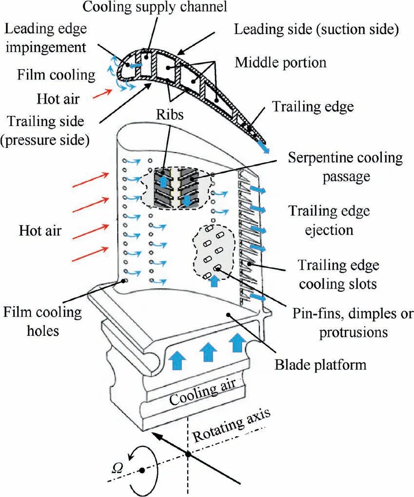
Fig.1 Typical gas turbine blade with internal cooling schemes.1
Fluid flows in rotating passages are different from those in stationary channels due to the development of secondary flows,such as Coriolis vortices from rotational effects.Because of the rotation,local heat transfer and friction factor augmentation levels are altered. It is noted that the flow and heat transfer for internal cooling of gas turbine blades containing the development data before 2010 in both stationary and rotating conditions is thoroughly elaborated in previous comprehensive reviews.1,2,8In this decade, besides, numerous researches on improving the turbine blade cooling performance have been performed continuously to explore the flow and heat transfer mechanism under rotating conditions. Also,numerical simulations with rotational effects need to apply complex turbulence models to obtain more accurate results.Results from many works in the literature are observed to present differently since parameters such as Reynolds number(Re), rotation number (Ro), buoyancy number (Bu), and any other related factor are examined in different ranges depending on the capability of applied tools.
Therefore, the purpose of this review is to elucidate the effects of rotation in gas turbine internal cooling from various recent investigations from the year of 2010.Related theoretical equations provided to understand the fundamental of rotational effects is presented in the following section. Then, the third part discusses the effects of rotation on different internal cooling schemes, which is then followed by the effects of the buoyancy parameter and the rotational effects on the friction factors in the fourth and fifth parts, respectively. Also, the most used experimental and numerical methods are briefly presented and finally, recommendations for future research are outlined in this paper.
2. Related theory of rotation
To understand the effects of the flow field under rotating conditions on the heat transfer, the derivation of the theoretical equations9is presented as follows:

where ξ is vorticity vector of the coolant,t is time(s),U is particle velocity vector, ν is the kinematic viscosity of the fluid(m2/s),φ is a scalar function,Ω is rotation vector,αVis a thermal expansion coefficient of the coolant(K-1),Twand Tinare wall temperature and bulk/inlet temperature (K), respectively.
Eq. (1) is well known as Helmholtz hydrodynamics equations where the first-two terms involve time variable and convection term; the third part is the vortex-stretching term and the fourth one means the viscous diffusion term. However, it is usually simplified into Eq. (2):

where ρ is coolant density (kg/m3), P is pressure (Pa) and μ is the dynamic viscosity of the fluid (N·s/m2). r is the position vector of the origin rotating frame (inertia frame), and rsis the position vector relative to the origin of the moving frame.The first and second terms are the Coriolis and centrifugal forces; the third term is the pressure gradient, and the last one is the viscosity.
In a rotating-turbine blade, the flow mechanism from a forced convection cooling channel and a jet impingement passage are different due mainly to the Coriolis force direction.Also, the coolant direction can be affected either radially outward flow or radially inward flow in a multi-pass channel. To firmly grasp the effect of rotation in a turbine blade, the force diagram of coolant fluid in a serpentine cooling passage, a jet impingement cooling passage,and a leading-edge/trailing-edge flow is demonstrated in Figs. 2–4, respectively.
In a serpentine channel, when the coolant is in a radially outward flow, Fig. 2(a), the rotating direction of the channel is Ω=Ωj, and the coolant main flow is U=ui+vj+wk.Hence, the Coriolis force and the centrifugal force term can be expressed as in Eqs. (3) and (4), respectively.

where Ω is rotational speed(r/min).X,Y and Z are the directions in Cartesian coordinate, while i, j and k are its vector.
As the Coriolis force direction is pointing to the trailing surface, the velocity flow is shifted toward the trailing side.Consequently, it can be expected that the heat transfer is enhanced on the trailing side,and it is decreased on the leading counterpart. When the coolant is in a radially inward flow,Fig. 2(b), the main flow changes to U=ui+vj-wk. The Coriolis force term can be re-written as shown in Eq. (5):

Since the displacement vector and direction of the rotation remain unchanged, the centrifugal force is the same as in Eq.(4), but its direction is against the direction of coolant flow.As the Coriolis force directs to the leading surface, the axial velocity flow is displaced toward the leading surface. Thus,heat transfer is increased on the leading surface, and it could be decreased on the trailing counterpart.
For an impingement cooling passage, when the injected jet discharges to the leading surface (leading orientation), Fig. 3(a),the main flow is U=ui+vj+wk and the velocity component u in X direction is greater than that in Y and Z directions.Hence, the Coriolis and centrifugal forces deflect the jet flow toward k. On the other hand, when the injected jet points to the trailing surface(trailing orientation),Fig.3(b),the coolant main flow modifies to U=-ui+vj+wk. Here, the Coriolis force directs to -k, while the centrifugal force remains the same in k. In this case, the deflection of jet may not be apparent as in the leading orientation. It is noted that although the jet flow is bent by Coriolis and centrifugal forces, the heat transfer can be either increased or decreased. This depends on other related parameters for jet impingement such as jetto-jet distance (S/dj), jet-to-surface distance (H/dj), Crossflow Ratio (CR), etc.
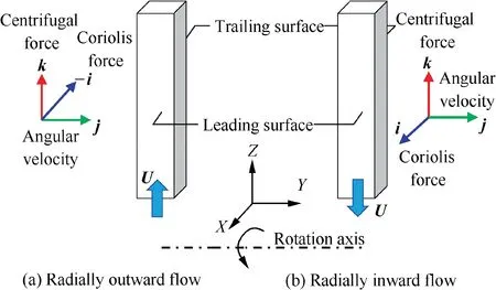
Fig. 2 Force diagram of coolant fluid in a serpentine cooling channel.
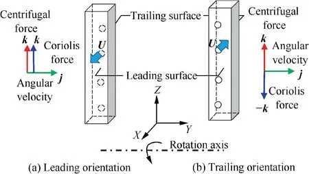
Fig. 3 Force diagram of coolant fluid in a jet impingement cooling passage.
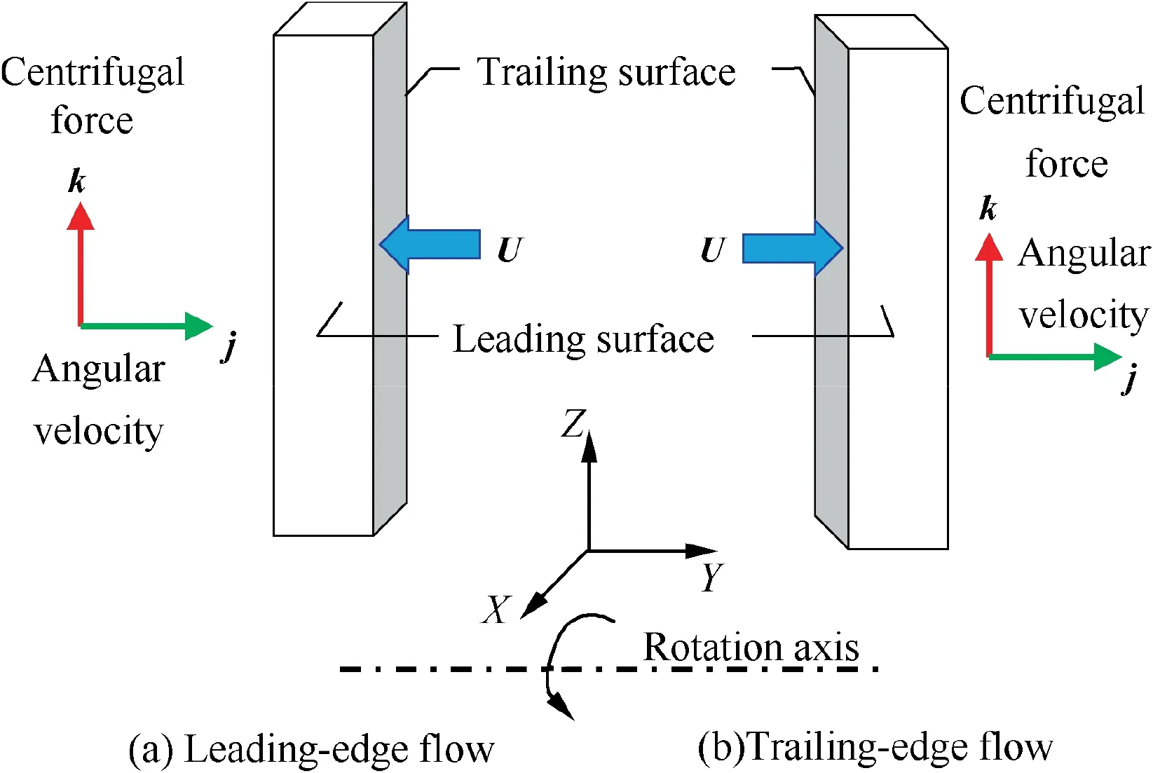
Fig. 4 Force diagram of coolant on leading-edge flow and trailing-edge flow.
In the case of leading-edge flow as illustrated in Fig. 4(a),generally, the coolant discharged from the supply channel to the leading-edge region in the axial direction,i.e. the direction perpendicular the radial one.Here,the velocity component v in-Y direction is dominant over that in X and Z directions.Similarly, in the trailing-edge flow, Fig. 4(b), the velocity component v in Y direction is the greatest. As a result, the cross product of the Coriolis term in Eq. (2) approaches zero(-2ρ(Ω×U)→0), and thus, there is no Coriolis force acting directly on these flow directions. However, in the modern turbine blade,the flow velocity in the trailing-edge region is more complicated since the coolant extracted from the serpentine channel is also involved. Consequently, the heat transfer behavior is similar to that in the mid-chord passage, which is elucidated in the next section.
3. Effects of rotation
The rotational effects on the flow and heat transfer can be attributed to two main factors: the Coriolis and buoyancy forces.The strength of the Coriolis force depends on the coolant velocity, the channel geometry, and the rotational speed,which can be combined to define the rotation number (Ro)as following:

where Ubis the bulk velocity (m/s), and Dhis the hydraulic diameter of a channel (m).
The buoyancy effects, generated from the high rotating speed and large temperature difference in the actual engine,are determined by the buoyancy parameter (Bu). Therefore,the rotation number(Ro),and buoyancy number(Bu)are generally used to study the rotational effects because the interaction of these two forces creates the complexity in the cooling channels. In many investigations of rotating channel flows with heat transfer,other parameters,such as Reynolds number(Re)and Density Ratio(DR),are also included for illustrating the flow and heat transfer characteristics. The Reynolds number are calculated by the following:

Meanwhile, the density ratio and buoyancy parameter are expressed from Eqs. (8) and (9), respectively.

where R is mean rotating radius (m).
From the Eq. (9), the buoyancy parameter depends on the density ratio(temperature difference),the rotating radius(centrifugal force)and the rotation number,whereas it can be also noticed that Bu is a square function of Ro. When accelerating the rotational speed (Ω), the Bu is increased significantly.Hence,the effects of buoyancy should not be neglected at high Ro,which is discussed later.In the following sections,the flow and heat transfer under rotational effects from various cooling methods applied to modern gas turbine blades are presented,including smooth channel cooling, rib turbulated cooling, pin fin cooling, jet impingement cooling, dimple/protrusion cooling, latticework cooling and swirl cooling.
3.1. Smooth channel cooling
Admittedly, to enhance heat transfer in gas turbine cooling passages, internal surfaces are roughened by turbulators, e.g.ribs, dimples, protrusions or pin fins; however, smooth channels, including two or multi passages, is investigated as references before placing the turbulators. Furthermore, simpler geometries, i.e. square shape, are considerably applied to achieve fundamental experiments.
A schematic diagram of the flow mechanism in a rotating two-pass square channel from Elfert et al.10is demonstrated in Fig.5.The Coriolis force induces the secondary flows developing counter-rotating vortex pairs in both radially outward and radially inward flows. Despite that, theses vortex pairs have different rotational directions, according to the flow direction in the first and second passages. Additionally, the structure of the vortex varies depending on channel geometries and channel orientation.11The Coriolis vortices also alter the axial velocity profiles in both passages. For the first passage with radially outward flow, compared to the mean stream velocity, the velocity increases near the Trailing Surface (TS);while for the second passage with the radially inward flow, it increases near the Leading Surface (LS). It has been observed in many studies that averaged heat transfer on TS was enhanced by more than 50%on the first passage,whereas heat transfer was decreased by 30% on the second passage.12–15
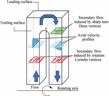
Fig.5 Schematic diagram of rotation induced secondary flow in a typical turbine internal cooling passage.10
Another important parameter that affects the flow and heat transfer in a rotating cooling channel is the critical rotation number (Roc). Generally, the positive effect of heat transfer on the TS and the negative one on the LS relating to the Coriolis force, appear when the rotation number is less than the critical rotation number (Ro Deng et al.16studied heat transfer in a two-pass smooth channel at high Ro using copper plate regional average method. Fig. 6 shows the local Nusselt number ratio (Nu⁄Nus)at different locations for first passage and second passage.In the first passage with radially outward flow, Fig. 6(a), the rotation always has positive effects on TS heat transfer at every location.For all Re tested cases,when the Ro is relatively low,the heat transfers on the LS are weakened by the rotation,but the trend of Nu⁄Nusis elevated at high Ro. Meanwhile, in the second passage with radially inward flow,Fig.6(b),unlike the radially outward flow, the Coriolis force acts toward the LS,resulting in higher heat transfer than the TS.This increase is small only at the upstream region (X/Dh=14.5) due to the influences of a sharp turn,12–15whereas, moving to the downstream, the heat transfer difference between LS and TS becomes more apparent. Moreover, the Nu⁄Nuson the TS is observed to surpass the LS, especially at a high Ro. Fig.7 is the schematic illustration of the flow mechanism at low and high rotation number for first passage and second passage. In the first passage, Fig. 7(a), at a critical rotation number,the flow on the LS starts to separate by the buoyancy force since the inertia force is weakened. For the higher Ro at the same location, a more prominent shifting of the bulk flow to the TS is formed faster than the cases with a low Ro. Also, a stronger buoyancy force forms a larger separation in the vicinity of the LS. At a specific location on the LS, when this separation moves inward, the Coriolis force acts on this flow,increasing in heat transfer on the LS. At the same time, in the second passage, Fig. 7(b), since the effect of the buoyancy force becomes more prominent at high Ro, it accelerates the flow near the hot wall, generating double peak velocity profiles. As the Ro keeps increasing, the reinforcement of these two peaks can be more clearly observed. Therefore, after the critical rotation number, the Coriolis force also acts towards the LS, which greatly enhances heat transfer on both surfaces at high Ro on both LS and TS. Fig. 6 Effect of rotation number on Nusselt number ratio at each location in smooth square U-channel.16 Fig. 7 Schematic of flow mechanism in first and second passage.16 Since the heat transfer is improved for both the LS and TS when the Ro is larger than the Roc, the Nusselt number correlation must be properly defined to accurately predict the heat transfer enhancement in the channel. Deng et al.16developed correlations to predict the Nu⁄Nusfor the smooth square U-channel in the ranges of Re=10,000–70,000,Ro=0–2.08. For the first passage, when Ro<1.31 the Nu⁄Nuscan be calculated from Eqs. (10) and (11) for the LS and TS,respectively. Recently,Hosseinalipour et al.17also proposed a novel correlation for estimating the Nusselt number(Nu)on the LS and TS based on Re, Ro and DR as shown in Eq. (15). where f1-f5are the coefficients of the Nusselt number correlation for both LS and TS as shown in Table 1. It should be noted that this correlation is valid for Re=5000–12000,Ro=0–0.15 and DR=0.04–0.1. For the region near the exit of the sharp turn,the Dean vortices produced from the curvature of flow streamlines around the bend are observed as shown in Fig.5.At low Ro,the rotation slightly affects the flow pattern at the bend region.18,19The heat transfer on the leading-bend surface is lower thanthat of the trailing-bend region,but at high Ro,the advantage of the LS appears gradually,which results in higher heat transfer than the TS.16,20In addition, the heat transfer in a fourpass square channel investigated using thermocouple technique by Li et al.9was observed to be higher in the first and third turning regions than the second turning region. This was due to the strong effect of the centrifugal force at the higher rotational radius.Moreover,this effect was more amplified at higher Ro. Table 1 Coefficients of Nusselt number correlation developed by Hosseinalipour et al.17 Although the high Ro shows strong effects on the heat transfer along the channels, it is not apparent at the channel inlet and outlet owing to the entrance effect.15,16,21Lamont et al.22measured heat transfer distribution in the developing flow channel at Re=12000 and Ro=0–0.5.They found that the entrance effect caused significantly high heat transfer,which also reduced the effectiveness of the ribs to further enhance heat transfer. In short, the flow field in a smooth channel is strongly altered at high rotation numbers, resulting in the noticeable change of the heat transfer in the passage for both radially outward and radially inward flows. However, as the turbulators are usually filled in the cooling channel, the flow and heat transfer characteristics are different from the smooth one.23,24 Earlier studies on cooling channels were primarily based on stationary conditions.There was a great amount of experimental and numerical progress on the impact of the turbulator shapes and configurations in the flow pattern and heat transfer distributions for single or multi-pass channels.The majority of the prior works showed that adjusting the rib configurations can either improve overall heat transfer or reduce the pressure drop penalty in the cooling channel. However, the stationary models neglected the effects of the Coriolis and buoyancy forces, which fluctuated the velocity, turbulence and temperature distribution under rotating conditions.Moreover,the secondary pattern induced by the rib turbulators was changed in the rotating passage.23,24Hence, the discussion of recent studies on the rotating-ribbed channel is provided in this section. Fig. 8 Contours of mean velocity with different rib pitch ratios(p/e=10, 12 and 15) for various rotation number (Ro=0, 0.26,and 0.52) at Re=10,000.28 There were numerous investigations of the flow structure in the rotating channel,especially with 90°ribs.25–27Recently,Li et al.28investigated the flow structure inside the rotating channel placed with 90° ribs utilizing Particle Image Velocimetry(PIV). Fig. 8 illustrates contour of mean velocity at different rib pitch ratios (p/e=10, 12 and 15) and various rotation numbers (Ro=0–0.52). The results show that as the Ro increases,the flow reattachment length on the TS is shortened,whereas it extends on the LS. However, when further increasing the rotation number(Ro ≥0.48),on the TS the shear layer re-stabilization occurs and shifts in the behavior of the secondary flows, causing a decrease of the Turbulence Kinetic Energy (TKE). A velocity deficit, caused by the impact of the Coriolis force and the momentum change of near rib flow,also occurs toward the TS. Furthermore, the rib pitch ratios(p/e) show a significant effect on the reattachment length. A large p/e relatively creates huge fluctuating vortices, which greatly affects the heat transfer in the channel. For extending the rib pitch ratios from 10 to 15, the separation length of the vortex on both the LS and TS extends.Hence,in the investigation of Li et al.,28the rib pitch ratio at p/e=10 shows the best arrangement under rotating conditions. Nevertheless,some existing literature showed that a smaller p/e had a positive effect on heat transfer.Lei et al.29studied the effect of rib spacing (p/e=5–10) on heat transfer in a twopass rectangular channel with channel aspect ratio of 2(AR=2)at Re=10000–40000 and Ro=0–0.45.They found that the Nusselt number ratio (Nu/Nus) increased with a decrease of p/e, but the effect of p/e on the heat transfer enhancement was small under rotation. Hagari et al.30observed similar results in a two-pass square channel with 60° ribs. They further concluded that heat transfer was more enhanced for smaller p/e owning to less interaction between the secondary flow. Fig. 9 Average Nusselt number ratios in term of rib spacing at Re=20000.31 Lately, Xu et al.31investigated the effects of asymmetrical rib spacing on heat transfer in a two-pass square channel at Re=20,000–50,000 and Ro=0–0.8. Different rib spacing was considered: p/e=3.8, 5, 6.4, 8, 10 and 14.4. On the positive direction rotation,the p/e on the TS was varied,keeping p/e=10 on the LS.The effects of p/e on surface averaged Nusselt number ratio(Nu-/Nu∞)is demonstrated in Fig. 9. The results show that when Ro<0.5, the smallest pitch,p/e=3.8, has the highest heat transfer, but for 0.5 Among the rib studies,currently,the effect of rib geometry in a rotating passage on heat transfer is also focused. Liu et al.11investigated heat transfer in a triangular duct with staggered 90°ribs,staggered 45° ribs and staggered invert 45°ribs at Re=10000–40000 and Ro=0–0.58. They found that at leading and trailing outer wall, a staggering invert 45° ribbed case showed the highest heat transfer, while the staggered 45° ribbed case was comparable to 90° ribbed one. Lamont et al.22observed the heat transfer distribution in developing channel flow from W- and M-shaped rib with two different angle attacks at Re=12000 and Ro=0–0.5. Results showed that W-and M-shaped ribs with an attack angle of 30°showed slightly higher heat transfer than those of 45°,but for most of the cases the heat transfer enhancement was similar to that of 90° ribs. For the case of ribs with the gap,the heat transfer enhancement is usually higher than that of continuous ribs. Liu and Lai32examined the heat transfer in a rotating triangular channel with discrete and V-shaped ribs at Re=15000–25000 and Ro=0–0.65. Results showed that heat transfer distributions in V-shape and discrete-V ribs were comparable, and both shapes provided higher value than that of 45°-shaped and discrete-45° ribs. A few years later, Wang et al.33performed a numerical study of variously shaped discrete 45° ribs in a rotating-rectangular channel at Re=10000 and Ro=0–0.7.It was observed that the trend of the heat transfer was increased with the rotation for all cases, and among all the studies, the case with the smallest gab obtained the highest heat transfer. Lately,Kaewchoothong et al.34conducted an experimental investigation of heat transfer in a two-pass square channel using steady-state liquid crystal thermography for four different cases, namely a smooth wall, a 90° ribbed wall, a 60° Vribbed wall, and a 60° V-broken ribbed wall. Fig. 10 shows the Nusselt number ratio distribution (Nu/Nu∞) in different cases for stationary (ST) and rotating condition (Ro=0.3)at Re=10000. For all cases, the rotation enhances the Nu/Nu∞on both LS and TS, particularly at the turning region due to the flow separation and the impingement of the flow on the end cap. The Nu/Nu∞for 90°ribs is slightly higher than those of the smooth cases, especially on the TS. Meanwhile, the V-60°ribs provide very high heat transfer since the angle of attack generates the secondary flows and high turbulent mixing between ribs. The rotation further increases the Nu/Nu∞on both LS and TS, but in the second passage, the slight enhancement is obtained on the LS. For the cases of broken V-60° ribs, the Nu/Nu∞is lower than those in the V-60° ribs on the first passage,but the heat transfer is more uniform.On the second passage, the Nu/Nu∞in the broken V-60° ribs is higher than that in the V-60° ribs, and high heat transfer occurs on the outer wall rather than the inner wall due to the effects of rib gab and sharp bend. The effects of rotation on the averaged Nusselt number ratio (Nu-/Nu∞) are plotted in Fig. 11 for first passage, turn region and second passage. Mostly, the trends of the average Nusselt number for all ribbed shapes slightly elevate as the Ro increases. In the first passage, Fig. 11(a), the V-60° rib obtains the highest value of Nu-/Nu∞on the TS due mainly to the effect of Coriolis force,35–38and the smooth channel shows the lowest heat transfer for both LS and TS.In the turn region,Fig.11(b),the general trends of Nu-/Nu∞are similar to those in the first passage, but the heat transfer variation between TS and LS is reduced for all cases except the smooth wall.Meanwhile,in the second passage,Fig.11(b),the increasing trends of the Nu-/Nu∞with the rotation numbers on both LS and TS are less obvious as in the first passage. Here, the broken V-60°rib has the highest Nu-/Nu∞on the LS compared to the other cases.Moreover,the heat transfer in the 90°rib is comparable to that in the smooth channel, particularly on the TS. Briefly, the trend of heat transfer in the ribbed channel is similar to those in a typical smooth channel at low Re for both radially outward and inward flow. Higher heat transfer is obtained in the first-pass TS and the second-pass LS, and this effect is more dominant at higher Ro.39,40Furthermore, the heat transfer is recovered in the counterpart surfaces when the Ro is higher than the Roc.41–43 However, the rotation is less effective on the heat transfer enhancement in the ribbed channel, especially at high Re due to the strong secondary flow induced by the ribs.Chen et al.42studied a two-pass 45°ribbed channel with AR=4 in the first passage and AR=2 in the second passage for three different coverage: less, medium and full at Re=10000–70000 and Ro=0–0.39. Fig. 12 shows the variation of the local Nusselt number ratio (Nu/Nus) against the Ro at low and high Re for first passage (Region 4) and second passage (Region 11). At low Re, the general trend of the heat transfer on the TS and the LS are similar as a typical ribbed channel, and the rotational effects are generally decreased with the increased rib coverage. However, the rotational effects are greatly reduced at high Re for all configurations. Rallabandi et al.44measured the heat transfer in a three-pass channel placed with 45°ribs at Re=75000–165000 and Ro=0–0.4.They also observed that at high Re, the asymmetry between LS and TS resulted from the effects of rotation was decreased.Moreover,the heat transfer in the second passage with the radially inward flow and at the turning region was significantly suppressed.This reduction was attributed to the suppression of turbulence generation owing to the buoyancy force acting on the warmer fluid and the bulk flow.45 Fig. 10 Detail of local Nusselt number ratio(Nu/Nu∞)in different cases for stationary and rotating condition (Ro=0.3) at Re=10000.34 Regarding the ribbed channel shapes,a rectangular channel at different aspect ratios (AR=1, 2 and 4) cast with 45° ribs was investigated by Liou et al.46at Re=5000–30000,Ro=0–0.2 and Bu=0.005–8.879. It was observed that as AR increased, the local Nusselt number ratio for both on the ribs and walls (Nuall/Nus) consistently decreased in both LS and TS due to the combined rotation-buoyancy effects and the area fraction of the ribbed surface. In short, the rotational effects were minor in a large channel aspect ratio.13Besides, another type of channel geometry, which is also observed to be employed at the mid-chord portion of a gas turbine blade,is the parallelogram channel.Due to its shape,only at the entrance,exit and turning region of the channel parallelogram cross-section caused higher degrees of the Coriolis force, enlarging local high Nusselt number regions than the square-cross section counterparts.41 For channel orientations(β),Huh et al.14studied the channel orientation at 90° and 135° in a 45° ribbed channel(AR=2) at Re=10000–40000 and Ro=0.12–0.45. When β>90°, the heat transfer on the first-pass LS was increased as the Ro increased,and the difference in the heat transfer level between the LS and TS was also smaller.39,40,47Later, Singh et al.38introduced a new design of a rotating two-pass channel cast with V-45° ribs. The aim was to utilize the Coriolis force favorably in both passages to enhance heat transfer and reduce non-uniform cooling performance caused by the rotational effects. Fig. 13 shows the detail of local Nusselt number ratio(Nu/Nu∞)for typical two-pass channel with an aspect ratio of unity,and proposed model obtained by changing the two-pass channel orientation. With the positive effect of the Coriolis force on the heated walls, the proposed design shows higher heat transfer enhancement than the typical two-pass ribbed channel, particularly on the second pass LS. Under rotating condition (Ro=0.1), the new design achieves Nu-/Nu∞at 4.68, while the typical one reaches Nu-/Nu∞at 4.25. In conclusion,in order to enhance heat transfer in the cooling channel, the channel shapes and orientations must also be taken into serious consideration, as it can determine the Coriolis force direction affecting the heat transfer in the rotatingserpentine passage. Fig. 11 Effects of rib shapes on averaged Nusselt number ratio in two-pass rotating channels at Re=10000.34 The heat transfer correlation with the rotational effects is different from that in stationary cases due to the addition of the Ro and Bu.It is noted that different proposed heat transfer correlations in rotating ribbed channels before 2010 have been documented by Han et al.1In recent years, a large number of experimental works for the rotating-ribbed channel have been performed to formulate the heat transfer correlation with a wide range of studies. Table 2 selects useful heat transfer correlations with the test conditions from different experimental ribbed channels. The correlations are divided into two main parts: the Leading Surface (LS) and the Trailing Surface(TS) as the heat transfer is largely different by the rotational effects. The method and deviation from each correlation are also included in the Table. Fig. 12 Effects of rotation number on LS and TS local Nusselt number ratio (Nu/Nus) at low and high Reynolds number.42 Previous studies showed that the heat transfer enhancement in a pin fin channel depended mainly on the pin configurations,such as the pin height (H/dp), pin spacing (S/dp), pin arrangement and row numbers of the pins. Most of the studies observed that endwall heat transfer was increased by decreasing the pin spacing, especially for streamwise direction.Besides,larger pin height provided better endwall heat transfer than the shorter one.48–50 Fig. 13 Detail of Nu/Nu∞on two-pass channel with two different aspect ratios at Re=20000.38 Currently, wide ranges of the experimental investigation were increasingly performed in the rotating pin fin channel.Rallabandi et al.51studied the heat transfer in a rotating pin–fin wedge-shaped channel for half-size and full-size pin at Re=10000–20000 and Ro=0–0.8. They found that the heat transfer was decreased when using the half-size pin since the level of disturbance to the counter-rotating vortex system is lower than the full-size one. For the overall trend, the rotational effects were very limited at mid-span and outer channel due to high velocities incorporated with the converging passage.Park et al.52used the naphthalene sublimation technique to measure heat transfer distribution in a rotating channel with inclined pin-fins (60° and 90°) at Re=7000 and Ro=0–0.2.Results showed that for both stationary and rotating condition, the pin–fin array with an inclination led to a reduction in heat (mass) transfer. However, the heat transfer on the LS and TS increased with the rotation, particularly for the inclined pin since the rotation promoted turbulent vortices around the upstream pin-end wall. Table 2 Existing Nusselt number correlations under rotating conditions from recent experimental rib studies. Huang et al.53measured the heat transfer in a rotating channel (AR=4) provided with five different nonuniform pin sizes (Blockage=24%–72%) at Re=10,000–20,000 and Ro=0–0.33. Fig. 14 shows the average Nusselt number ratios (Nu-/Nus) in different nonuniform pin sizes for both LS and TS.In all cases,the Nu-/Nus on the TS are higher than those on the LS as in the typical ribbed channel. The rotation has,however,a less effect on heat transfer enhancement for the cases with blockage lower than 36%, while it is beneficial on the TS at blockage of 60% due to enhancing flow through the pin fin gaps. In a stationary case, the staggered pin fin arrangement was observed to generate a higher heat transfer than the inline configuration because the mixing between mainstream flow was relatively poor in the inline arrangement. Meanwhile, under the rotating condition, the heat transfer results were different.Huang et al.54investigated the effects of rotation on heat transfer for a pin–fin channel with different channel orientation and pin–fin arrangement using steady-state liquid crystal thermography. Fig. 15 presents the Nusselt number ratio contour from staggered array and inline array for two different channel orientations under rotating conditions. For all cases,the local heat transfer on the TS is higher than the LS. In the staggered pin array, Fig. 15(a), the high heat transfer is observed in front of the pin, but the heat transfer difference between LS and TS is reduced, particularly for the β=150°.Conversely, in the inline pin array, Fig. 15(b), at Ro=0.1,higher local heat transfer is obtained in the case β=90° due to the lower generation of wake flow behind the pin. As the Ro increases to 0.39, however, the heat transfer contour on the TS is extremely high only at the downstream pin fin. This effect is harmful to the cooling channel due to the degradation of heat transfer uniformity and a large difference in heat transfer between LS and TS. Fig. 14 Effect of nonuniform pin size on at Re=10000–20000.53 It should be noted that the correlations(Eqs.(16)–(19))can be used to predict in the ranges of Re=5000–20000,Ro=0–1.4 and Bu=0.004–3.6. Jet impingement is applied mainly for the cooling of the thermally high-loaded leading-edge region. Multiple jets are, also,observed to be utilized in double-wall configurations, which presents further increasing cooling performances for the turbine internal flow.57–59Flow and heat transfer characteristics of the jet impingement heat transfer with non-rotating conditions have been intensively explored in previous reports.From the existing literature, the heat transfer of the impingement system depends on the following factors:jet and feeding channel configurations, Reynolds number, and direction of crossflow removal.6,7 In cases of the rotating jet impingement, due to the direction of the Coriolis and centrifugal forces, the jet flows are affected by the jet orientation respect to the rotation axis (θ).In the investigation of the rotating jet impingement, there are three main orientations: front or axial orientation(θ=0°), leading orientation (θ=+90°) and trailing orientation(θ=-90°),as illustrated in Fig.17.Commonly,the front orientation is examined for the leading edge of a turbine blade model,60–63while the leading and trailing orientations are investigated for the double-wall configuration on the LS and TS, respectively.64–67 Fig. 16 Effects of rotation on for different configurations at Re=10000.54 3.4.1. Leading-edge model with curve surface The leading-edge model consists of a concave or trapezoidal impingement passage connected with a supply duct with radially outward flow. Generally, the heat transfer is measured over a range of feeding channels or jet Reynolds numbers(Re=10000–40000 or Rej=6000–24000). The rotation number of the feeding channel based on the coolant velocity at the channel inlet (Ro) varies from 0 to 1.4, while the average rotation number for the impinging jet (Roj) ranges from 0 to 0.13.60 In the feeding channel,the heat transfer is enhanced on the TS and reduced on the LS due to the Coriolis force as a typical phenomenon for a radially rotating smooth channel.However,in the region near the closed end,the heat transfer is increased sharply as compared with the stationary cases.This is because of the pumping effect, caused by both the Coriolis and centrifugal forces, and this effect becomes more obvious when the Ro increases or Re decreases.60–62 Fig. 17 Sketch of jet orientation relative to rotating axis.57 For the impingement channel,since the jet flow direction is parallel to the axis of rotation (θ=0°), there is no Coriolis force acting directly on the jet; however, the Coriolis and centrifugal force is observed to change the shape of the jet stagnation.The jet flow structure was investigated by Massini et al.62using PIV at Rej=30,000 and Roj=0–0.05. To identify the hub, midspan and tip sections of the turbine blade, the ratio between mass flow rate leaving the model through the feeding channel outlet and the total coolant flow entering the blade,defined as Crossflow Ratio (CR) was set at 70% (hub), 40%(mid) and 10% (tip). The results showed that the jet flow was almost not affected by the rotation at the hub and midregion, but the jet flow was rotated towards the LS at the tip area as illustrated in Fig. 18. Elston and Wright60conducted an experimental investigation on heat transfer in an impinging jet-row semi-cylinder channel (S/dj=4.0, H/dj=3.2, θ=0°) at Rej=6000–24,000 and Roj=0–0.13. Fig. 19 shows the Nu/Nusfor each streamwise region in the impingement passage. The results show that only the upstream channel (Region 9) is affected by the rotation due to the absence of crossflow.In this region,thus the heat transfer is enhanced greatly for all surfaces,particularly on the LS. In addition, Jung et al.68observed in staggered jet concave channel (Sx/dj=3.0, Sy/dj=2.62, H/dj=3.0, θ=0°) that the spent flow accumulates more on the TS. At higher Ro,the rotational effect reduced the ability of the jets to penetrate the spent air because the jet deflected toward the LS was greater.They also found that the curvature effect in the leading edge promoted flow mixing and strengthened the turbulence intensity at the stagnation region. The separated peaks occurred in the stagnation point,resulting in higher heat transfer on the LS. Fig.18 Effects of rotation on flow field in an impinging-row(S/dj=3.75, H/dj=2.34, θ=0°) at Rej=30000.62 Nevertheless, for the real leading-edge region in a turbine blade, there is an acute angle between the jet direction and the rotation axis (θ=-30° and -45°). Cocchi et al.69performed an experimental study of a jet-row in a similarengine impingement channel (S/dj=2.9, H/dj=2.5 and θ=-35.6°) at Rej=20000–50000 and Roj=0–0.008 using transient liquid crystal thermography. Fig. 20 shows the spatially resolved Nu/distributions for stationary and rotating condition. For all crossflow ratio tests, the peaks of the heat transfer are shifted toward the TS under rotating conditions.70Also, the rotation seems to decrease the local heat transfer,and such an effect occurs to be strong at a low crossflow. This has been interpreted as the combination of Coriolis effects on the feeding channel,in which the flow is driven away from the jet holes inlet,and on the jets themselves,in which the lateral expansion is decreased. Cocchi et al.71also studied the impingement with two different geometries. Fig. 21 shows the effects of rotation on the average Nusselt number () at three different crossflow ratios. For all cases, the () increases with Re, and the decrease in () due to the rotational effects can be observed for both geometries. However, as the CR increases, the heat transfer reduction by the rotation is diminished because the strong crossflow subjugates the Coriolis force on unbalancing the jet flow. Moreover, Case B with smaller holes and bigger numbers provides higher heat transfer than Case A because it shows much better exploiting the jet-wall interaction,particularly at a high crossflow ratio. Overall, it can be concluded that the rotation generates negative effects on the heat transfer enhancement in the leading-edge model. To improve heat transfer rates and that of uniformity in the leading-edge impingement channel under rotating conditions,a Double-Swirl Channel (DSC) with race-track shaped jets has been tested numerically by Wang et al.72Fig. 22 presents the velocity and temperature gradient distribution for four tested cases in both stationary and rotating conditions. Compare to the semi-cylinder channel with both cylindrical holes and racetrack holes, the jet in the cases of DSC maintains at higher velocity until it impinges on the target surface for both stationary and rotating conditions. This is because two antirotating swirls are generated by the DSC.73The DSC cases,also,show a lower temperature gradient,resulting in desirable temperature distributions in terms of temperature uniformity.For the cases of DSC with race-track holes,Fig.22(d),furthermore,the jet velocity is higher than the round jet due to reducing of the streamwise crossflow.74Overall, the combination of the DSC and the racetrack jets can be a good choice to improve the performance at leading-edge turbines as it provided higher heat transfer with lesser sensitivity to the rotational effects. 3.4.2. Double-wall configuration Fig. 19 Effect of rotation on area average Nusselt number ratio on impingement surface at Rej=6000–24,000.60 Fig.20 Spatially resolved Nu/Rej0.6 distributions in the impingement channel for stationary and rotating condition.69 Impinging jets in a typical double-wall model can be observed in all directions as illustrated in Fig.17.For jet in leading orientation (θ=+90°), due to the combined effect between the Coriolis and centrifugal forces, the jet deflection is more prominent than that in the front orientation (θ=0°). The stagnation points for each jet is shifted to the outward direction, which might collide with adjacent jet generating a crossflow-like effect on the jets, particularly at downstream.At high H/dj, this effect becomes evident at the downstream because the negative effect of the crossflow is greater.66In contrast to the jet in trailing orientation (θ=-90°), since the direction of the Coriolis force is inward, which opposes the centrifugal force, the velocity pattern is similar to noncrossflow results. However, the double-wall configurations have a low jet-tosurface distance, H/dj≤1. The heat transfer is observed to be considerably different from higher jet-to-surface distance cases,H/dj>1,because of two factors:potential core development and the strong crossflow effect. When the potential core does not reach the convergence before impingement,the velocity dissipates over the distance, causing low heat transfer on the surface. The centerline velocity is the greatest when the potential core converges due to continuity. Besides, under the rotational effects, the Coriolis force acts on this potential core, which develops the length and the size of the shear layer as sketched in Fig. 23. Moreover, at the low H/dj, the crossflow is observed to bend the downstream jets for both trailing and leading orientation. Lamont et al.65compared the heat transfer in an impingement channel (θ=±90°) with different jet-tosurface distance (H/dj=1–3) at Rej=9000, Roj=0.0022 using transient liquid crystal thermography. Fig. 24 plots thearound the jet at different H/djfor stationary, leading orientation and trailing orientation.For all cases at H/dj=1,theincreases at the downstream jets(Jet number 6 and 7),since high mass flux through the impingement channel leads to low static pressure at these regions, resulting in higher coolant extracted from the downstream jets. For the narrow impingement area,the trailing orientation also experiences the Coriolis force favorably,enhancing heat transfer.Meanwhile,the leading orientation deteriorate the heat transfer.66,70Overall, the heat transfer results by jet impingement are similar to the traditional two-pass channels,but with the additional complexity of crossflow and jet-to-surface distance. Apart from that,modern studies attempted to increase heat transfer on the impingement channel by modifying the impingement surface. Roughness elements on the surface can increase turbulence on the impingement channel and guided the wall jet flow, resulting in a further increase in the heat transfer.59,75,76Moreover,it was examined by several researchers that the combination of jet impingement with obstructed elements and external effusion holes reduced negative crossflow effects,resulting in higher heat transfer enhancement.59,77For stationary conditions, it can be safely deduced that the roughness walls showed an enhancement of the heat transfer over the smooth surface. Under rotating conditions, however, Singh and Ekkad78showed that the impinging jet on rough surfaces did not always lead to enhance heat transfer. Fig. 25 shows the average Nusselt number ratio normalized with the stationary-smooth surface (Nu-/Nus,sm) for three different dimpled target walls at stationary and rotating conditions. The results showed that the slight enhancement is obtained in stationary cases,whereas the rotational effects on both leading and trailing orientations show a great deteriorate of the/. Therefore, to use rough elements in the rotating-impingement channel,designers should pay more attention. Fig. 21 Rotational effects on average Nusselt number in two different impingement geometries for different crossflow ratios.71 Fig.22 Normalized velocity and temperature gradient distribution at stationary and rotating condition for four different impingement cases.72 To reduce the impact from the Coriolis force under rotation,a two-pass channel associated with jet impingement channels was introduced by Yang et al.64as shown in Fig.26.It was observed that this model had high heat transfers at the end of the channel for both the supply channel and the impingement duct.It was also less sensitive to the rotational effect compared to the two-pass ribbed passage. Moreover, the Nu/Nuscorrelated from the experimental results was also constructed to predict the heat transfer enhancement from both the supply channel and impingement passage as shown in Eq. (20). Fig. 23 Potential core development at different jet-to-surface distances under rotation.65 Fig. 24 Average heat transfer around each jet number between H/dj cases.65 Fig.25 Average Nusselt number ratio for three different surface modifications at Rej=2500.78 Fig.26 Sketch of two-pass channel with impingement developed by Yang et al.64 where f1and f2are the coefficients for the correlation under rotation as shown in Table 3. It should be noted that the Re range for this correlation is from 25000 to 100000, and the Ro ranges from-0.14 to 0.14,where Ro is negative on the LS. Dimple is a new cooling scheme that is firstly introduced by Schukin et al.79Compared with smooth channels, the dimple provides reasonable heat transfer augmentation with minimal pressure loss penalty. The main reasons for the improvement of the heat transfer achieved by the dimples are flow reattachment, flow impingement, and upwash flow at the downstream region of the dimples, but the heat transfer could be deteriorated due to flow separation and recirculation in the upstream region of the dimples. Many recent investigations attempt to reduce the negative effects by modifying the dimpled shapes.80–83Most of the results from the modified dimples reduce flow separation and recirculation flow inside the concavity or even generate strong secondary flows developed in the dimple,which further enhances the heat transfer.However,among the different geometric parameter investigation, the channel height to dimple diameter ratio (H/ddim) and dimple depth ratio (δ/ddim) are reported to have the largest impact on the flow structure and heat transfer levels. The rotational effects on the dimpled channel cooling were also taken into consideration by many researchers. Flowstructure and heat transfer in a rotating dimpled channel were studied by Elyyan and Tafti84using Large Eddy Simulation(LES) at Re=12500 and Ro=0–0.7. The velocity streamlines at the center of the dimple are demonstrated in Fig. 27.The results show that as the Ro increases, the recirculating zone is smaller in the trailing dimple concavity, resulting in the early reattachment in the downstream concavity. This can be attributed to the buoyancy force, which further pushes the near-wall hot fluids toward the center of rotation (radially inward flow).Meanwhile,the recirculating flow is larger in the leading counterpart, causing a slow reattachment in the concavity. In addition, the shrinkage and growth of the recirculation flow inside the shallower dimples are observed to be more dominant than those in the deeper dimples. Table 3 Correlation coefficients for jet impingement model from Yang et al.64 For the heat transfer enhancement, it was observed that at low rotation number (Ro ≤0.4), the average Nusselt number ratio on the dimples and channel walls (Nuall/Nu∞) was increased in the trailing dimple and decreased in the leading counterpart. However, the increase or decrease in the heat transfer appearing in the dimpled wall remained almost constant at high Ro, and values of the critical rotation number were extended slightly when using a deeper dimple. Fig. 27 Mean velocity streamlines at center of dimple for δ/ddim=0.2(top)and δ/ddim=0.3(bottom)with different rotation numbers.84 Griffith et al.85also measured the heat transfer in a rotating channel(AR=4)provided with dimples at Re=5000–40,000 and Ro=0.04–0.3 using the copper plate technique. Fig. 28 shows the averaged streamwise Nusselt number ratio (Nu/Nu∞) between smooth and dimpled surface for β=90° and β=135°. The results illustrate that the dimpled wall obtains higher enhancement than the smooth channel as Ro increased,especially on the TS.Meanwhile,the dimples on the LS present little dependence on the Ro.Furthermore,the channel orientation at 135° experiences higher overall enhancement than the channel orientation at 90°.Kim et al.86further concluded that the heat transfer on the dimpled wall was less sensitive to the rotation compared to the smooth surface since the dimpleinduced flow was stronger than the Coriolis force induced the secondary flows. Although the dimples can increase the heat transfer in a gas turbine blade, using the dimples on the blade internal wall could weaken the structural integrity and stiffness. Some researchers have proposed heat transfer augmentation using protrusions to avoid the drawbacks of the dimples. The protrusion is one kind of convexity that presents significant heat transfer enhancements. In a rotating protruded channel, however, the flow structure and heat transfer are different from those in the dimple. Fig. 29 demonstrates velocity friction lines (streamline that very close to the surface) on the rotating protruded surface revealed by Elyyan and Tafti.87Compared to the stationary cases, Fig. 29(a), a growth of the wake region behind the protrusion on the LS can be seen since the Coriolis force causes the flow less energetic. Weaker impingement and delayed flow reattachment are also observed when increasing the Ro,Fig.29(b) and (c). On the other hand, for the TS, Fig. 29(d) and (e),the wake region behind the protrusion is shrunk owing to the increase in the velocity and impingement effect,but it does not change significantly at high Ro. Overall, the impact of the Coriolis forces on the flow structure for the protrusion is not as strongly evident as it acts in the dimple. The heat transfer in a rotating channel roughened with staggered protrusions at Re=5000–12500 and Ro=0–0.6 has been investigated by Chang et al.88using an infrared camera.They observed that as the Ro increased, the average Nusselt number ratio on the protrusions and walls (Nuall/Nus) on the TS was always higher than on the LS.However,on the LS,the heat transfer was initially reduced, then it was recovered at Ro ≥0.1.Also,the rotating-protruded wall produces larger heat transfer enhancements than other cooling methods, including smooth wall,1290° ribs,3545° ribs,23,43pin–fin channel,55dimpled surface85as shown in Fig.30.In addition,it can be noticed that at fixed Ro(by varying the density ratios),the heat transfer is increased with Bu.This point is discussed in the next section. Fig. 28 Effect of Ro on streamwise average Nusselt number for smooth and dimpled surface at two-different orientation.85 Fig. 29 Velocity streamlines near protrusion surface at protruded height (δ/dpro=0.2).87 Moreover,a set of heat transfer correlations were proposed for LS and TS as in Eqs. (21) and (22), respectively. Latticework duct (also known as vortex cooling structure or bounded vortices structure)is an alternative cooling technique that has been used by some Russian gas turbines. Fig. 31 demonstrates the gas turbine blade provided with the latticework cooling structure. The latticework consists of repeatedparallel ribs. The ribs on the TS directly contact with the ribs on the LS. The two sides of the ribs are oriented at a certain angle, which is called as the crossing angle. The typical flow path of cooling air in the latticework is also presented in Fig. 31.89,90Coolant entering the latticework turns the flow direction at turning regions and impinges onto the beginning of the opposite sub-channel. This pattern is repeated continuously until the coolant flows out of the latticework. From the above mentions,the main advantage of this cooling method is overall heat transfer enhancement levels with substantially high-pressure loss compared to the traditional rib turbulators in the serpentine channel.The detail of the heat transfer coefficient in the latticework cooling has shown the first time by Bunker.91It was found that primary surface heat transfer was enhanced over the smooth duct, particularly at each turn. Throughout the channels, the local heat transfer coefficient distributions were remarkably uniform excepting at the turning region. Moreover, the channel with a narrow width presented higher heat transfer levels, especially at a low Re. For a rotating latticework,Acharya et al.92have carried out based on the experimental work obtained by Bunker.91Fig.32 shows the on spanwise Nusselt number ratio on the walls and rib surfaces(Nuall/Nus)along with the streamwise distance(Xs/Dh,s)with different sub-channel rotation number(Ros).At low Res(Reynolds number based on the hydraulic diameter of the sub-channel), Fig. 32(a), significant effects of rotation can be observed clearly in the second half of the channel. The heat transfer enhancement decreased substantially at a higher Ros,causing the Nuall/Nuslower than 1. However, the first half of the cooling channel is unaffected by the rotation. The rotational effects are also insensitive at high Re, showing only a small decrease with the Rosas illustrated in Fig. 32(b). Fig. 30 Variation of Nuall/Nus against Ro on LS and TS from different cooling schemes in ranges of Re=5000–12500.88 Fig.31 Schematic of latticework cooling turbine89 and a typical flow path used in a trailing edge region.90 Moreover,Carcasci et al.90showed that the heat transfer in the latticework was insensitive to channel orientation (β). The reason was due to the significantly added surfaced area, viscous or frictional effects that restrained the secondary flow.92Compared to the flow in straight smooth and ribbed passages,the secondary flow patterns generating along the channel were difficult to maintain its strength because of the repeated turning of the flow through the perpendicular bend. Overall, the heat transfer of the latticework is relatively insensitive to the rotation, especially at a high Re. Oh et al.93also measured the heat (mass) transfer at Re=10500–44000 and Ro=0–0.8 using naphthalene sublimation technique. Surprisingly, as the Ro increased, the average heat transfer increased at the LS and changed slightly in the TS.This was reversed from conventional rib channels with radial outflow where the Coriolis force increased heat (mass)transfer in the TS. The heat transfer difference between the LS and TS was also less significant.Moreover,when considering the overall heat transfer, the latticework cooling channel enhanced heat transfer significantly due to the remarkably increased heat transfer area, which can be higher than the ribbed channel.94 Fig. 32 Rotational effects on spanwise Nusselt number ratio with streamwise distance in latticework duct.92 Lately, an investigation of the flow structure in a latticework under rotating conditions was also revealed. Du et al.95performed a numerical study of flow structure and heat transfer in a broken latticework duct at Re=44,000 and Ro=0–0.5. Fig. 33 shows the effect of rotation on Nuall/Nu∞in both LS and TS for six different broken rib cases. Compared to the traditional latticework duct(Case 0),the broken ribs near the middle region (Case 2) and turn region (Case 3) provide higher heat transfer. For all cases, as Ro increases, the Nuall/Nu∞on the TS, is slightly decreased, whereas the Nuall/Nu∞on the LS is substantially increased.93 For the flow field in the broken latticework,it was observed that as Ro increased, the velocity near the sidewall,which was responsible for the upward spiral flow, remained almost constant in the trailing subchannels. Conversely, the velocity was increased in the leading subchannels, resulting in heat transfer enhancement on the LS, especially near the impingement region.93In conclusion, for both stationary and rotating conditions, the fluid flow over the latticework channel was dominated by the upward spiral and helical flows, and the upward spiral flow was responsible for the high heat transfer. As the leading edge of turbine blades suffers from the mainstream with extremely high gas temperature and velocity, it should be paid more attention to the leading-edge cooling method.Alternatively,a swirl cooling generated by strong circumferential flow is very effective in achieving high heat transfer rates. The first idea of the swirl cooling was developed by Kreith and Margolis,96then heat transfer performance of the swirl cooling system was continuously improved in numerous subsequent researches. There were two effects, which mainly benefit the heat transfer along the swirling passage: the redistribution of the axial mass flow to the channel and the turbulence induced by swirl. Compared to traditional impingement cooling, the swirling flow showed a drastic increase in heat transfer rates with remaining heat transfer uniformity.97–99 The factors affecting heat transfer in the swirl cooling system such as the channel geometry, tube surface, the jet number, spacing and angle, swirl number, or even the combination with normal impingement,were extensively investigated in earlier research.100–103In a stationary case, it was worth noting that the flow is sensitive highly to the downstream channel. With modifying the channel outlets, the flow field entire the tube was completely changed. In short, high heat transfer was obtained at high Reynolds numbers or high swirl numbers, but this caused high-pressure loss along the swirl channel. An investigation on heat(mass)transfer of the swirl cooling under rotating conditions was studied by Winter and Schiffer104at Re=10000–40000 and Ro=0–0.36.Circumferential injected positions were also varied.Fig.34 shows the effects of rotation on Sherwood distribution at different lengthwise coordinate of the tube (x/D) for Re=10000, Re=20000,and Re=40000. Here, D is the diameter of a tube (m), and the Sherwood number(Sh)is dimensionless mass transfer coefficient, which can be calculated using the local differences in the naphthalene layer before and after the experiment.104Generally, the heat (mass) transfer increases as Re increases. For all cases, the rotations are less effect on heat (mass) transfer.Only at low Re and high Ro, the Coriolis force shows a slight effect on the swirling flow. This is because the swirl stabilizes the fluid flow and substantially suppresses the effect of the Coriolis force generated under rotation. Moreover, the injected positions are reported to have a slight influence on the heat transfer distribution, particularly at low Reynolds number (Re=10000) and high rotation number (Ro=0.36). Fig. 33 Average Nusselt number ratios (Nuall/Nu∞) in broken latticework duct.95 Fig. 34 Sherwood distribution in rotating swirl tube for different Reynolds numbers.104 The buoyancy parameter (Bu) is used to reveal the buoyancy effects (density variation) because of large temperature differences and high rotational speed in an actual engine. The Bu of internal cooling passages can be also varied depending on channel geometry.13,46Since the Bu is increasingly elevated by the Ro,the effects of rotation and buoyancy are always coupled. There are several investigations on the buoyancy effect on heat transfer.Coletti et al.25observed the coupling between Coriolis and buoyancy in a rotating ribbed channel using PIV.The 90° ribs with p/e=10, e/Dh=0.1 was tested at Re=15000 and Ro=0–0.38. The result of in-plane mean stream tracers between 6th and 7th ribs are demonstrated in Fig. 35. With the addition of the buoyancy effects, the flow pattern on the LS is completely changed as illustrated in Fig. 35(d).This is because the ribbed wall heated up the adjacent fluid layer generating the opposite direction of the buoyancy to the main flow. Due to the reverse flow, the buoyant mixing layer is created causing a high momentum core, which is not curved toward the wall. The buoyancy effects further extend the size of recirculation over the whole inter-rib distance and the size is increased higher than the rib height. Meanwhile,on the TS, the flow pattern is almost not altered by the effect of the buoyancy, but the smaller size of the recirculation flow can be observed as shown in Fig. 35(e). Although the heat transfer seems to decrease on the LS,the buoyancy effects in many investigations is observed to increasefor both LS and TS. Li et al.21studied the buoyancy effects on heat transfer in a smooth square U-channel at Re=10000–70000, Ro=0–2.08 and Bu=0–12.9. Fig. 36 shows the buoyancy effects on Nu/Nusat each surface for first passage and second passage.For both cases,before the critical point, the effect of Bu is limited, whereas after that, the Nu/Nusshows increase rate. The location near the entrance is almost not affected by the Bu due to the entrance effect,while the location near the turn obtains higher Nu/Nussince the effect of Coriolis and centrifugal forces are stronger. Chang et al.105also conducted an experimental investigation for a parallelogram channel provided with 45° ribs at Re=5000–15000, Ro=0–0.3 and Bu=0.001–0.23. The results showed that the buoyancy effect increased the heat transfer,and the distributing Nusselt number patterns on both LS and TS remained similar as Bu varied. These consistent results were also observed in other configurations, e.g. the rib-triangular duct11and the protruded channel.88 Since the DR also affects the Bu as illustrated in Eq. (9),several studies varied the heat flux to isolate Bu from the Ro,in which the local αV(Tw-Tin) is accordingly changed.20,21Liou et al.106studied the isolated effects of rotation and buoyancy number on heat transfer in a two-pass parallelogram channel with 90° ribs at Re=5000–20000, Ro=0.0.3 and Bu=0.0015–0.122.It was found that the individual buoyancy effect improved local heat transfer within the examined range,but the effects decreased rapidly as the Ro increased. Fig. 35 In-plane mean stream tracers for different condition.25 Fig. 36 Effect of buoyancy number on Nu/Nus at each surface in the first and second passage.21 On the other hand,there were several studies found the negative buoyancy effects on the heat transfer. Liou et al.46observed that the isolated buoyancy effects reduced the heat transfer performances in the rectangular channels of AR=2 and 4. Besides, in the pin–fin channel (AR=8) examined by Chang et al.,56increasing in the Bu decreased the heat transfer at all measured locations. However, the degrees of buoyancy impacted on the heat transfer reduction were weakened rapidly as the Ro increased. For the jet impingement case, Elston and Wright60showed that the jets are deflected more toward the leading surface of the impingement cavity as the Bu increased. The deflection reduced the jet momentum, which could not penetrate the crossflow inside the cavity.Hence,the heat transfer at the stagnation was decreased, and this negative effect was more pronounced at the downstream channel. Moreover, it was observed by Chang and Yu70in the impingement trapezoidal channel that the buoyancy effect reduced Nu-/Nus especially on the TS followed by LS and stagnation region, respectively.In summary, the Bu should not be neglect when actual engine operating conditions (high Ro and large DR) are considered since it shows a large influence on the heat transfer in various cooling methods. Fig.37 Effect of rotation on average friction factor ratio(/f∞)for different cases at Re=10000.34 Fig. 38 Effect of rotation on area-averaged friction factor ratio (/f∞) with different Re.106 Experimental techniques are crucial to obtain accurate heat transfer on measured surfaces. The range of experimental parameters can be conducted at actual engines or simplistic models depending on the measurement tool and available capability.In last two decades,the experimental methods,such as thermocouple technique, copper plate regional average method or LCT (Liquid Crystal Thermography) have been used to evaluate heat transfer coefficient. Several research groups have also used mass-transfer analogy, such as naphthalene sublimation technique to measure heat transfer coefficient since it has no heat loss and axial conduction effect. In addition to heat transfer measurement,the flow field measurements, such as hot-wire anemometry, LDV (Laser Doppler Velocimetry) and PIV (Particle Image Velocimetry) have been adopted for the understanding of heat transfer phenomena.Besides, numerical predictions have been applied to reveal the details that are difficult to obtain by experimental techniques. Several numerical methods, e.g. RANS (Reynolds Average Navier-Stokes), DES (Detached Eddy Simulation),LES(Large Eddy Simulation),etc.have been employed to predict flow and heat transfer for gas turbine internal cooling.The information of the experimental methods and numerical modeling before 2010 has been reviewed elaborately by Han et al.1 With rotating condition, a great number of researches has been carried out to explore the flow and heat transfer characteristics although the rotating frames are much more difficult to set up. Likewise, numerical simulations under rotational effects have been simulated with complex turbulence models to obtain more accurate results.Since 2010,similar experimental methods and numerical modeling have been executed to measure the heat transfer and flow field for turbine internal coolant channel. For heat transfer measurement among the recent experimental works, TLCT (Transient Liquid Crystal Thermography) is the most famous technique followed by copper plate regional average method and steady-state infrared thermography.In TLCT,the test surface is assumed to be a semi-infinite solid wall with a force convective condition. When the mainstream temperature is changed, the wall temperature can be calculated as following108: where nmaxis the time step number of one local pixel reaching the specified wall temperature (Tw). Generally, in order to calculate the heat transfer rate, the Twis calibrated with wall temperature measured by a thermocouple. A hue-based calibration technique is also applied to relate the liquid crystal color change with the measured surface. The heat transfer coefficient can be determined from Eq. (24), and the Nusselt number is calculated by Eq. (25). where kfis thermal conductivity of fluid (W/(m·K)). For the copper plate technique, the regionally average heat transfer coefficient is evaluated by following: Fig. 39 Schematic of rotating rig and illustration of test section using transient liquid crystal thermography.65 Fig. 40 Detailed Nusselt number distribution normalized with stationary-smooth surface (Nu/Nus,sm) in rotating-developing channel flow at Re=12,000.22 Fig. 41 Two dimensional contours and streamlines of mean velocity measured from LES and PIV in rotating ribbed channel.109 where I and V are the electrical current and voltage supplied to each copper plate,Atotis total heater area(m2),and Qlossis the heat losses from each copper plate during the experiment. Similarly, for the steady-state infrared thermography, a thin foil is heated up by electrical current and voltage, and it is cooled by the mainstream flow.The heat transfer coefficient is then obtained by calculating the temperature distribution from the opposite thin foil, painted with nonreflective black color.20,41,88In addition, for transient infrared thermography,the rotating rig and the measurement detail are similar to the TLCT, except that the infrared camera is applied to capture temperature dissipation instead of using high-speed camera in the liquid crystal technique. The infrared thermography method has several advantages over the liquid crystal technique. For example, it is not bounded to the operating temperature ranges. The infrared camera is also pre-calibrated for temperature, which reduces the time and cost for color calibration. However, the infrared thermography is very costly, and the transparent window for capturing the temperature dissipation from the internal cooling tests must be additionally installed.1 The schematic of a rotating frame and illustration of a test section (a row of impinging jet) measured by the TLCT is shown in Fig. 39.65A rotary union is used to allow coolant from a stationary air supply to the rotating test section.A slip ring is applied to transmit temperature data from the test section to a data acquisition unit.On the test section,a high-speed camera is mounted on the rotating arm to film the color change, and the liquid crystals are applied on the test surface(rib or impingement wall). A black backing coat is painted to allow for the camera to track the color change.Commonly,the wall temperature thermocouple is also attached on the top wall of the liquid crystal coating to calibrate the color hue.22,65–67 Fig. 40 demonstrates the heat transfer distribution measured by the TLCT for different rib shapes in the rotatingdeveloping channel flow.22In both stationary and rotating conditions, the TLCT shows to well capture the heat transfer dissipation on the surface for the different rib cases. More intense heat transfer is obtained on the TS at higher Ro, especially for M-shaped ribs, in which the secondary flow converges, enhancing heat transfer on the surface. Lamont et al.108also applied this technique, and showed that it provided accurate and reliable, high resolution heat transfer distribution. For the flow field measurement in the rotating channels,PIV is the most utilized method since the high-speed camera and a continuous laser can be simply fixed on the rotating frame. PIV is an optical method, which is used to obtain instantaneous coolant velocity and seeding particles.The laser pulses separated by a time difference based on flow speed are generated, and the high-speed camera captures a doubleexposure image. Eventually, the particle image displacement is assigned from the autocorrelation of the image intensity dissipation. In the recent numerical investigations, LES, as the most accurate and expensive computational simulation, is widely employed to numerically simulate the flow and heat transfer in the rotating channel.84,87,109,110Hybrid RANS/LES or DES can be also observed in several investigations.26,63This might be due to the available of high computational tools in nowadays.LES is the method to numerically solve PDEs(Partial Differential Equations) for the turbulent flow. The larger eddies in the turbulent fluids simulated by LES are resolved explicitly, which can provide instantaneous solution, while RANS can provide only averaged results. Fig.41 compares mean velocity from LES(left column)and PIV (right column) in the rotating 90° ribbed channel at Re=15000 and Ro=0.38 for stationary, leading side and trailing side. LES mean velocity result in non-rotating conditions,Fig.41(a)and leading side,Fig.41(b)matches well with PIV measurement, in which LES correctly captures the large recirculation bubble for both cases. The difference can be observed in the trailing side case, only between the rib where high velocity gradient and flow curvature occurs.109,110Overall, the main modification of the recirculation zones are well captured by LES. Moreover, the heat transfer results revealed by LES were observed to agree very well with the experimental investigations.84,87 According to the literature review,the rotational effects of various cooling schemes are well understood. However, most of the prior studies, the Reynolds number are in the ranges of 10000 ≤Re ≤50000, which has been applied only for aircraft gas turbines. Also, the rotational effects largely change the local heat transfer from the stationary tests. Hence, some issues can be further investigated as follows: (1) The local heat transfer characteristics from different rib/pin–fin geometries, especially for realistic cooling channel shapes and orientations,with or without film cooling holes at higher Reynolds numbers, rotation numbers and buoyancy numbers is recommended for future experimental investigations. This is because the rib/pin–fin configurations can strongly influence the heat transfer uniformity in the rotating channel.34,54The uniformity factor is crucial to prevent the rotor turbine blade from failure due to the local hot spots. (2) For jet impingement at leading-edge turbine blades, different cooling models,e.g.Double Swirl Cooling(DSC),tangential jet, swirl cooling or swirl-impingement composition combined with film cooling holes, should continue by the experimental investigation at higher Reynolds numbers and high rotation numbers to identify the best cooling performance. (3) For double wall configuration, more experimental studies of higher heat transfer enhancement with lower pressure loss penalty under rotating conditions can be extended by incorporating the various types of surface modifications and film cooling holes. (4) Different dimple/protrusion shapes, e.g. teardrop, oval or V shapes, should be experimentally studied under rotating conditions.It can be combined with other cooling techniques, such as rib-dimple/protrusion or pindimple/protrusion to provide the best heat transfer augmentation. (5) The correlations from novel cooling schemes, e.g. dimple/protrusion, latticework and swirl cooling are rarely observed. Hence, the correlations from wide ranges of parameters in these cooling schemes have to be formulated to predict the heat transfer and pressure drop in the rotating channel. In the present review, an extensive literature review has been made to illustrate the rotational effects on various gas turbine internal cooling schemes from recent experimental and numerical investigations. The extensive results, which are collected selectively from the year 2010, include the effects of rotation on the flow field and heat transfer followed by the effects of the buoyancy parameter. Also, the rotational effects on the friction factors for the different cooling models have been reviewed. Moreover, the most used experimental and numerical methods in the recent studies has been briefly presented.The main conclusions can be drawn as follows: (1) The flow field in the cooling passage is strongly altered at high rotation numbers, resulting in the noticeable change of the heat transfer. Due to the Coriolis force acting on the coolant,for radially outward flow,the heat transfer is enhanced and reduced on the trailing surface and the leading side, respectively. For the radially inward flow, these results are reversed at a low rotation number, whereas the heat transfer on both sides is increased when the rotation number is higher than the critical rotation number due to a strong effect of the buoyancy force. (2) The rotational effects on the heat transfer in the channel provided with different types of cooling methods, e.g.rib, pin fin, dimple/protrusion or latticework, are reduced as compared to the smooth channel. This is because rotational-induced flows are suppressed by strong secondary flows induced by the turbulators,especially at high Reynolds numbers. The heat transfer difference between the leading and trailing surfaces is also decreased when larger blockage turbulators are used in the channel. (3) For the impinging jets in a leading-edge model, even though the jet flows are not directly altered by the Coriolis force due to the parallelism of the jet and the rotation axis (θ=0°), the jets bend toward the leading surface. The spent flow also accumulates more on the trailing side. Meanwhile, when the acute angles(θ=-30° to -45°) are used, the peaks of the heat transfer are changed toward the trailing side. Overall,the heat transfer in the leading-edge impingement channel is decreased as the rotation number increases.In the double wall model with the leading (θ=+90°) and trailing (θ=-90°) orientations, the jet impingement heat transfer are similar to the typical two-pass channels, but with the additional complexity of crossflow and jet-to-surface distance. (4) Compared to traditional jet impingement,the swirl cooling greatly reduces the effects of rotation due to stabilizing the fluid flow in the swirl tube, resulting in a lower heat transfer difference between the leading and trailing surface. (5) The buoyancy parameter is observed to increase the heat transfer in many researches. The buoyancy effects in all cooling schemes must be then paid attention when examining at actual engine conditions with high rotation numbers and large temperature differences because it shows a great effect on altering the heat transfer in the channel. (6) The friction factor for the internal cooling methods is determined mainly by the Reynolds number. At low Reynolds number, the friction factor is increased as the rotation number increases,whereas at high Reynolds number,it is decreased as the rotation number increases.This is because the strong flow field suppresses the rotational effects to alter the pressure drop inside the channel. (7) Most of the recent investigations uses transient liquid thermography method to measure heat transfer on the surfaces, followed by copper plate techniques and steady-state infrared thermography,respectively. Meanwhile, PIV is the most popular tool for the flow field measurement. Besides, in the current studies LES is widely used to numerically reveal the flow and heat transfer characteristics in the rotating internal cooling gas turbine. Declaration of Competing Interest The authors declare that they have no known competing financial interests or personal relationships that could have appeared to influence the work reported in this paper. Acknowledgement The authors gratefully thank for the support of the National Science and Technology Major Project (No. 2017-III-0009-0035),and the National Natural Science Foundation of China(Nos. 51676119 and 11972230).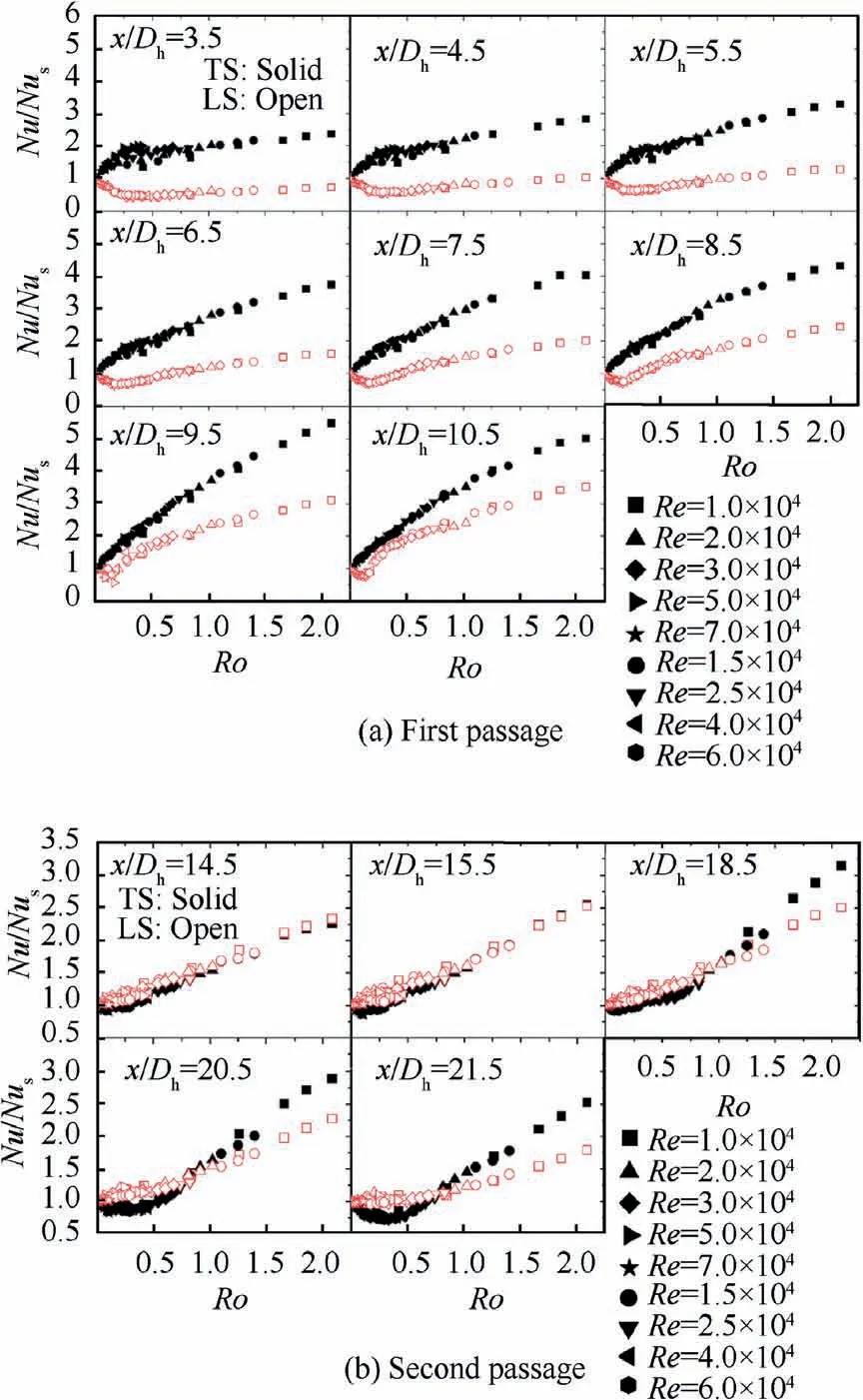
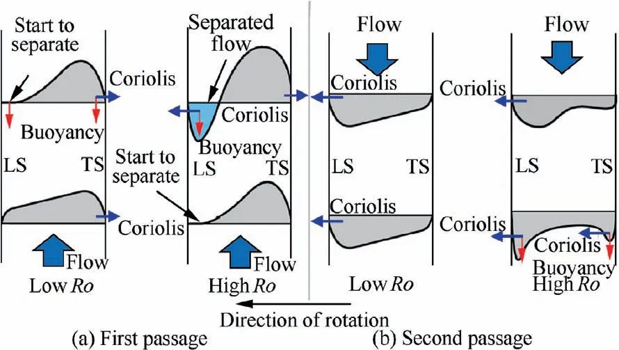
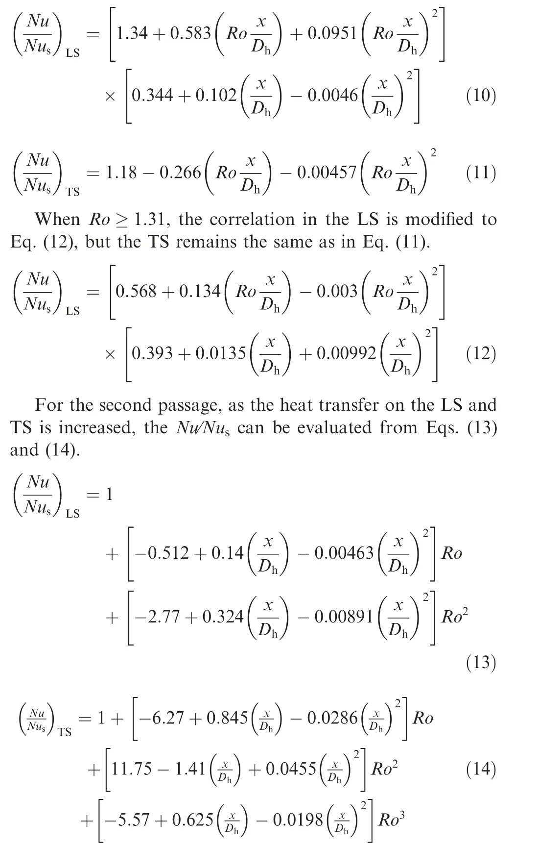


3.2. Rib turbulated cooling
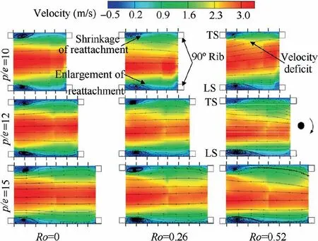

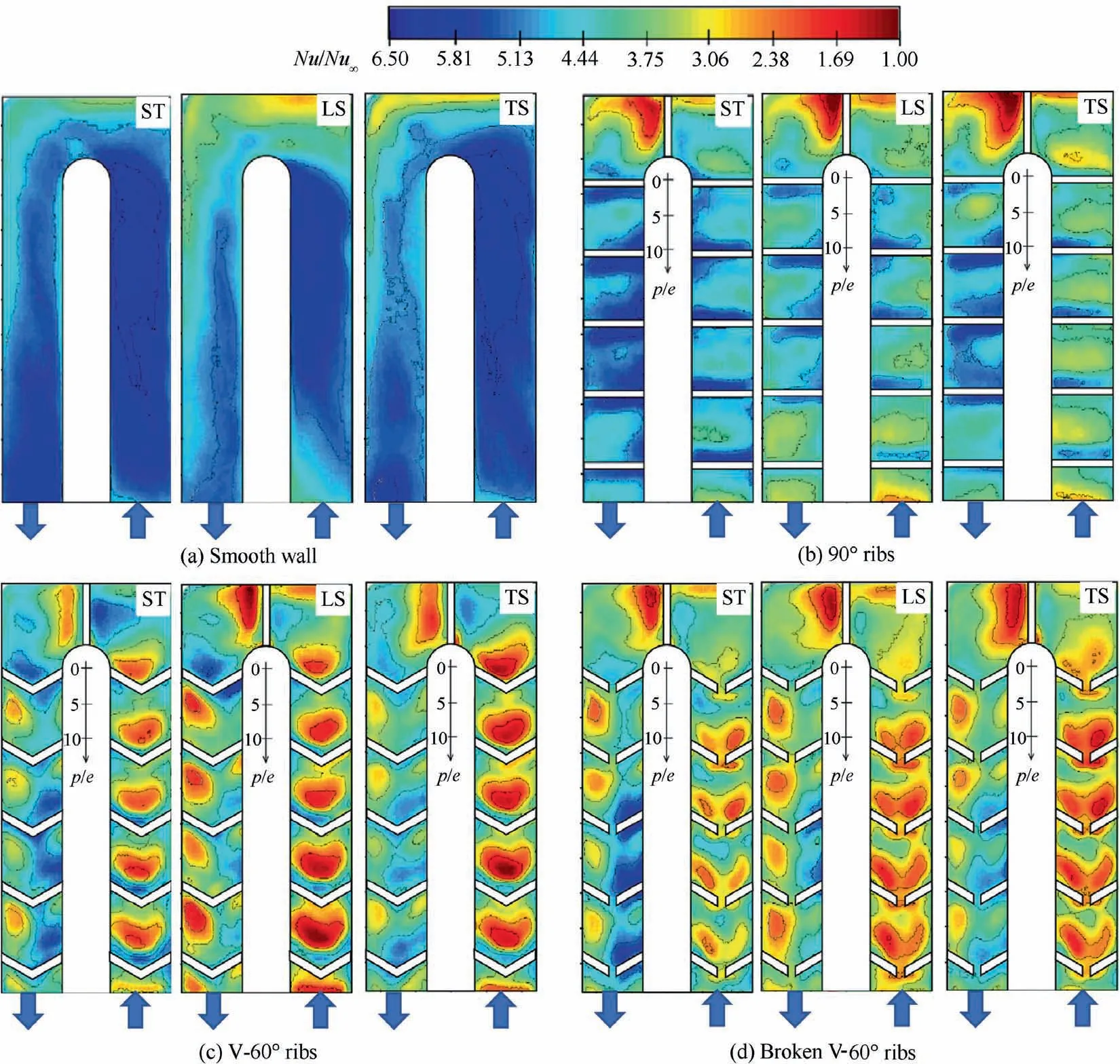
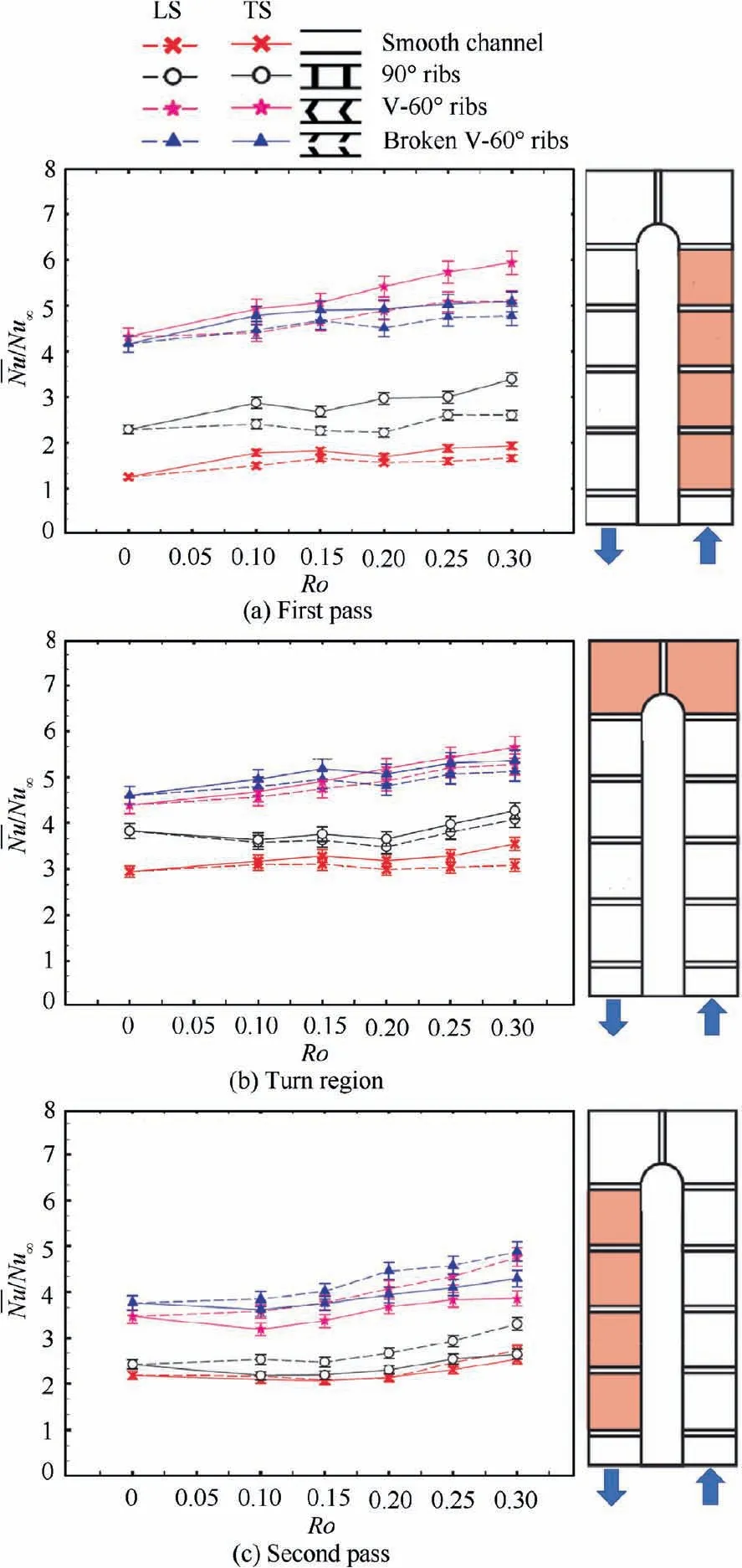
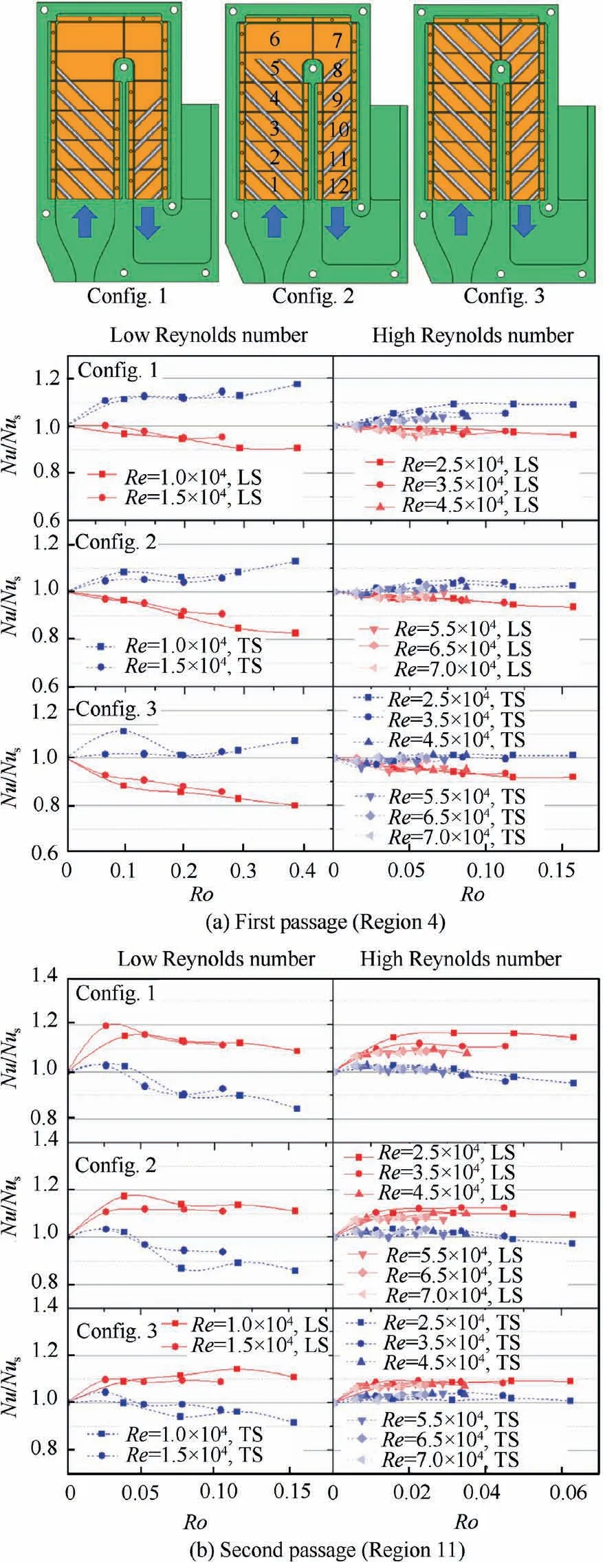
3.3. Pin fin cooling
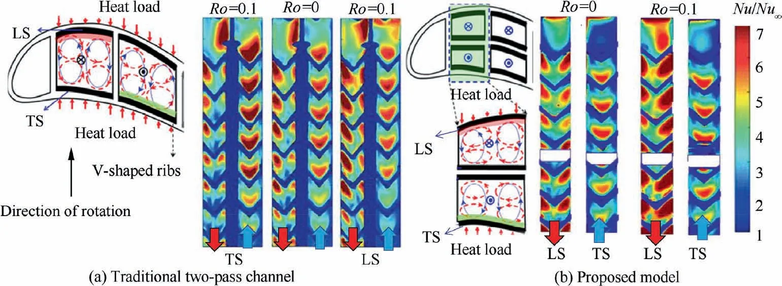
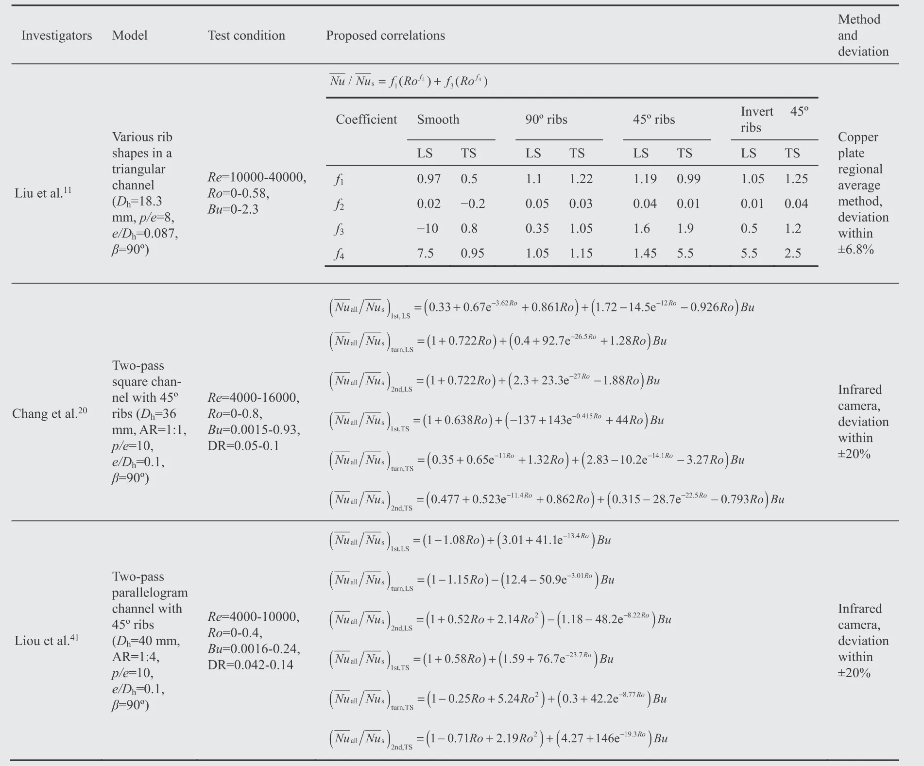
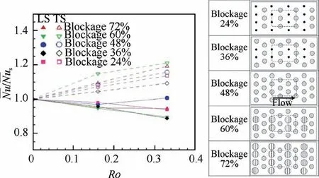
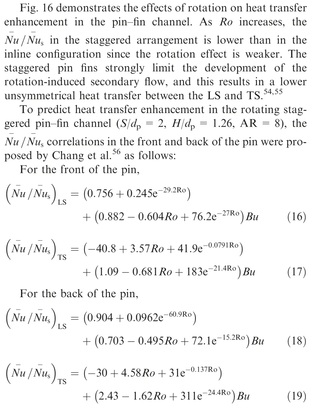
3.4. Jet impingement cooling
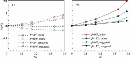
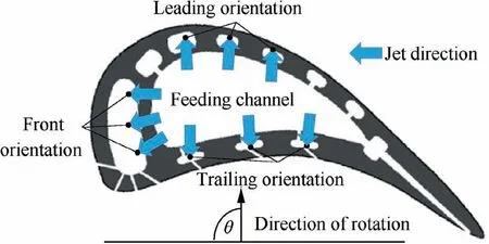
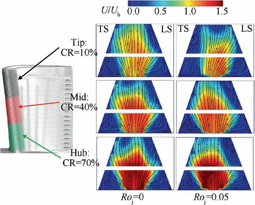

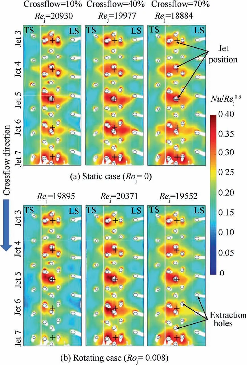
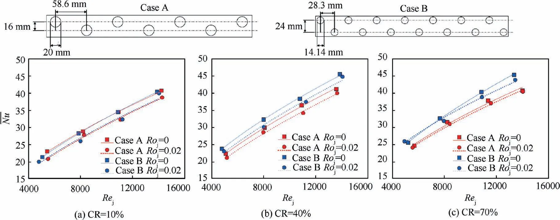
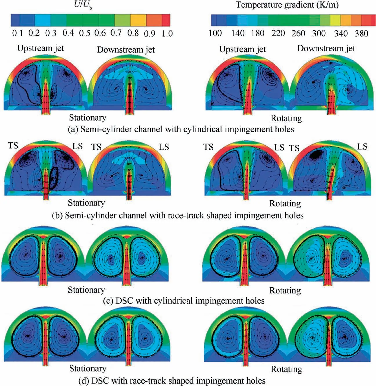


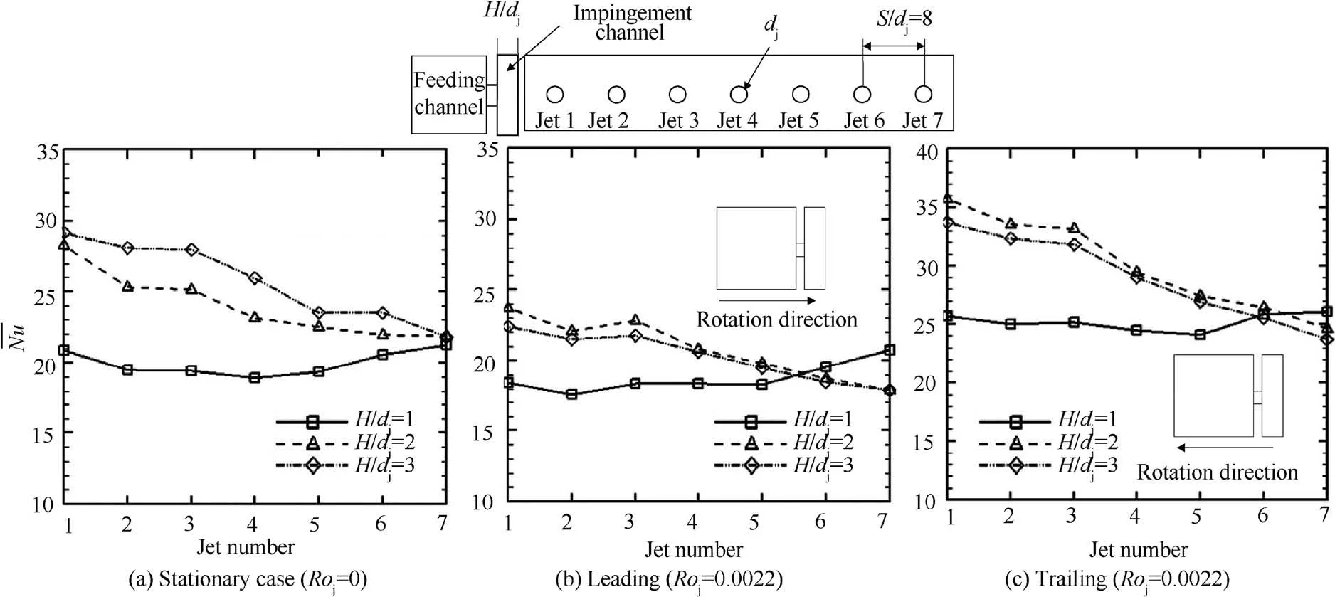
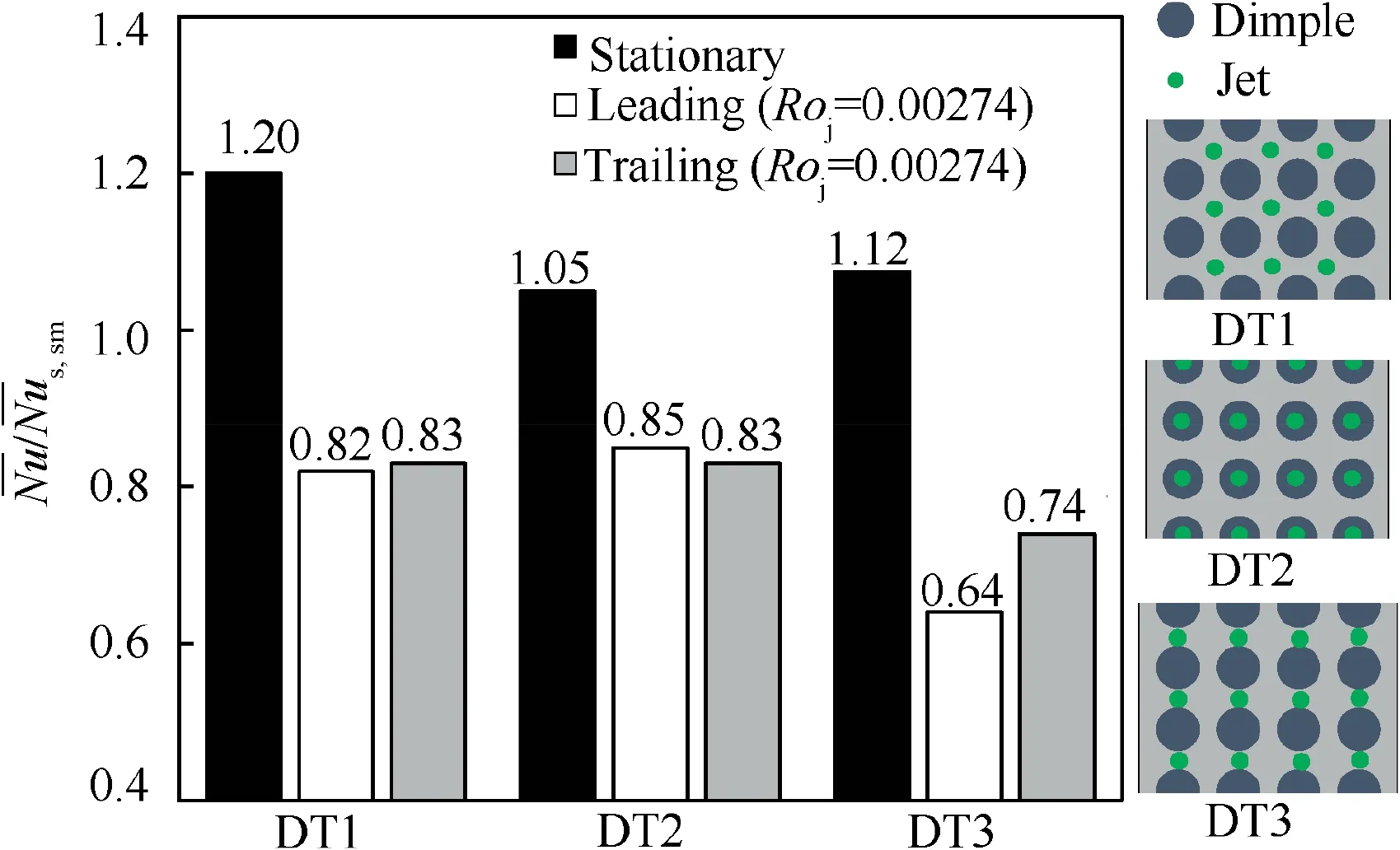
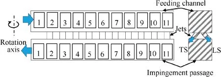
3.5. Dimple/protrusion cooling

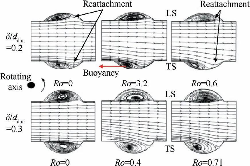
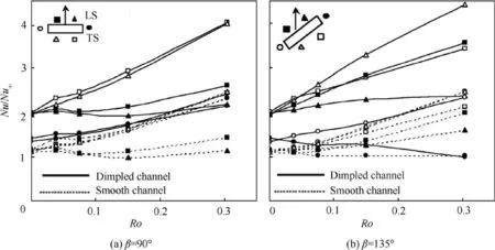
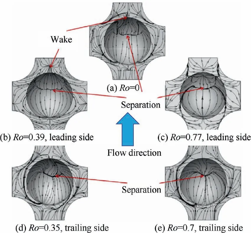
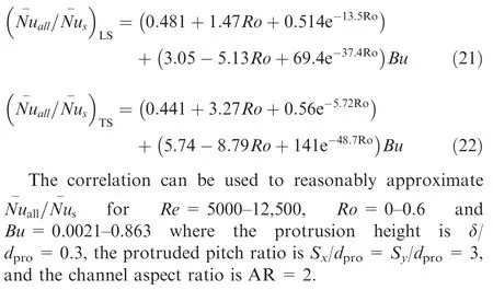
3.6. Latticework cooling
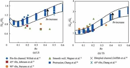
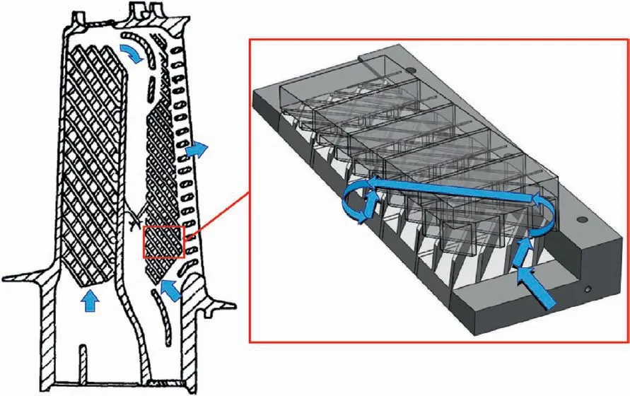
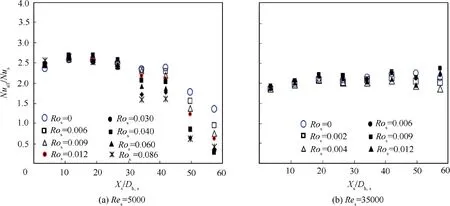
3.7. Swirl cooling
4. Effects of buoyancy
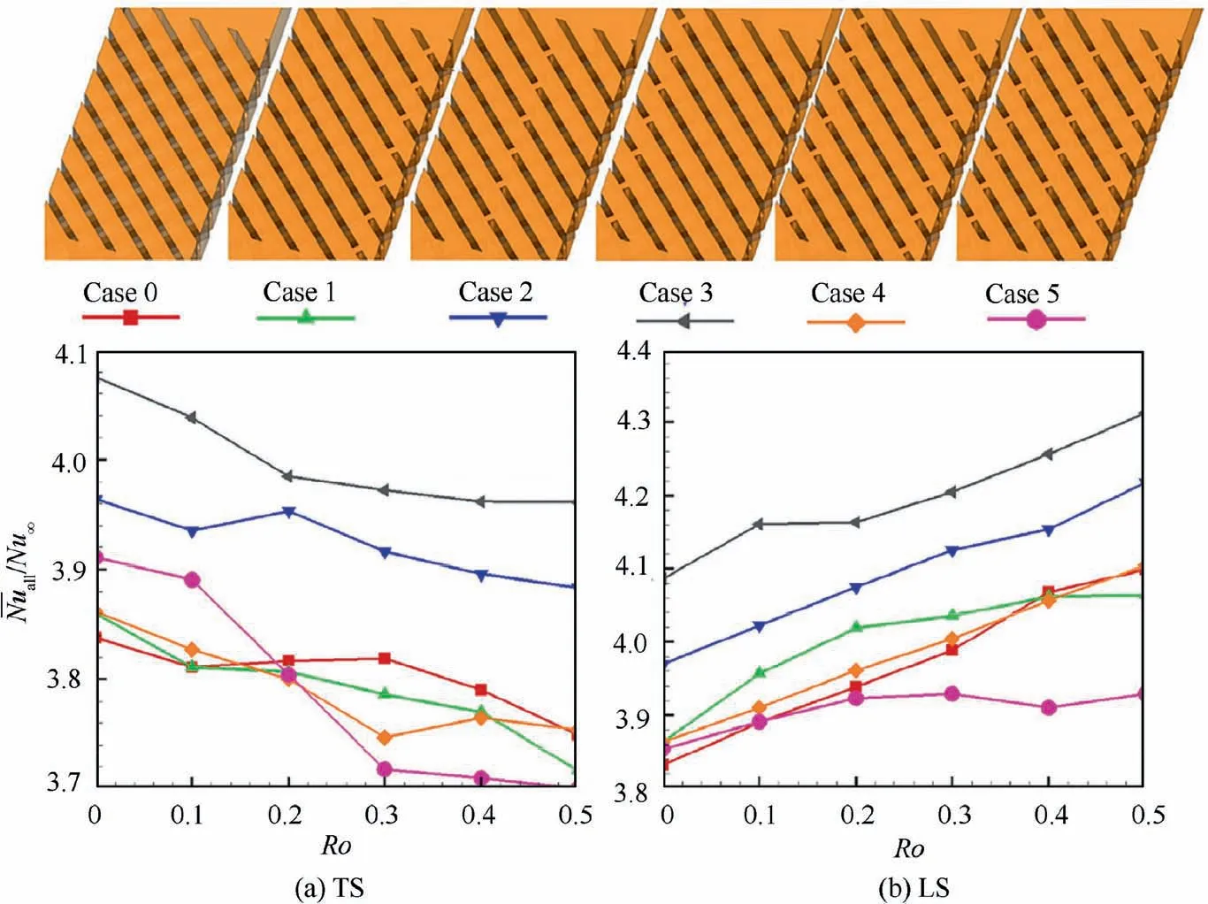

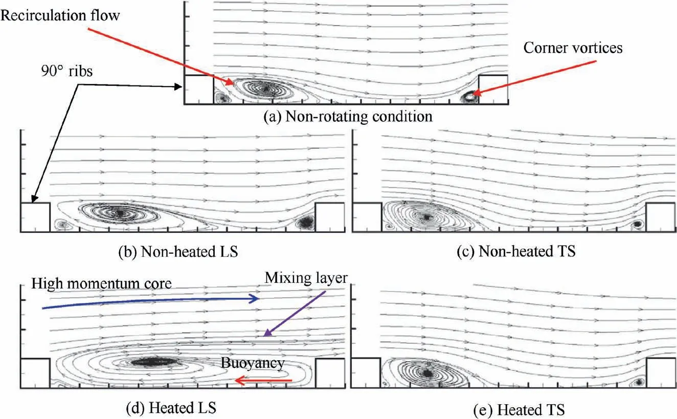

5. Rotational effects on friction factor
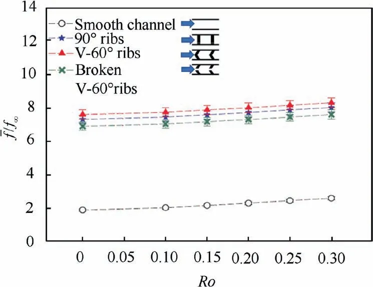

6. Experimental methods and numerical modeling


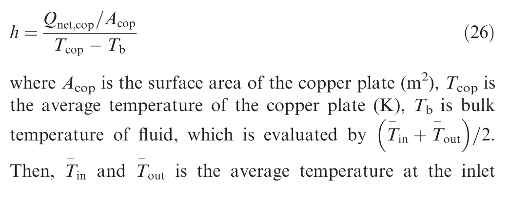
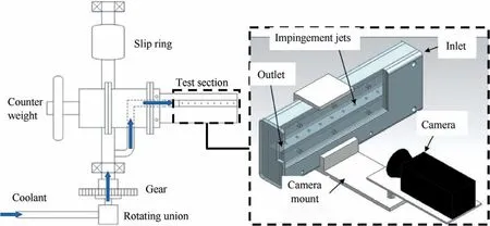
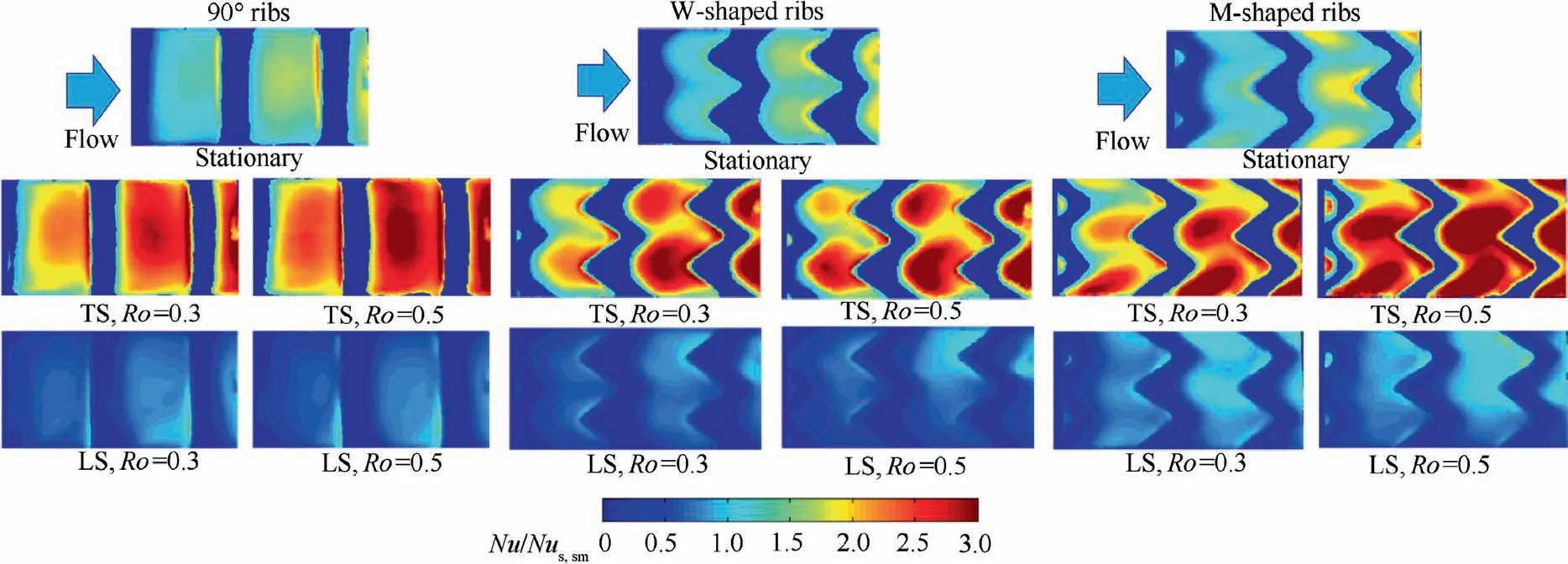
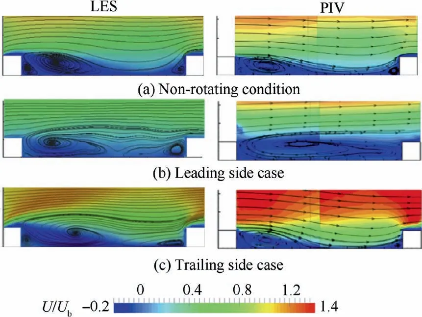

7. Recommendations for future research
8. Conclusions
 CHINESE JOURNAL OF AERONAUTICS2021年7期
