Parameter studies and evaluation principles of delamination damage in laminated composites
Kngkng WANG, Liin ZHAO,*, Himing HONG, Jinyu ZHANG,Yu GONG
a School of Astronautics, Beihang University, Beijing 100083, China
b Shenyang Aircraft Design and Research Institute, Shenyang 110035, China
c College of Aerospace Engineering, Chongqing University, Chongqing 400044, China
KEYWORDS Analytical model;Composite;Delamination;Evaluation principles;Parameter study
Abstract Delamination represents one of the most severe failure modes in composite laminates,especially when they are subjected to uniaxial compression loads. The evaluation of the delamination damage has always been an essential issue of composite laminates for durability and damage tolerance in engineering practice. Focusing on the most typical and representative elliptical delamination issue,an analytical model simultaneously considering the conservative buckling process and non-conservative delamination propagation process is implemented. Various computational cases considering different delamination depths, directions, aspect ratios, and areas are established,and the predicted results based on the analytical model are carefully compared.Effects of these geometrical delamination parameters on the buckling,delamination propagation,and failure behaviors of composite laminates are thoroughly analyzed,and innovative evaluation principles of the delamination damage have been concluded. It is found that the delamination area is the key factor that truly affecting the failure behaviors of delaminated composites,and the local/global buckling and failure loads show clear linearity with the delamination area, whilst the delamination depth and direction only have slight effects.
1. Introduction
Composite materials are increasingly used in aerospace engineering because of their excellent mechanical behaviors.However, inter-laminar properties of laminated composites are usually weak1,2due to their inherent characteristics, and thus delamination damage turns to represent an extremely critical damage mode.3–5The integrity of laminates would be evidently weakened when the delamination damage occurs, directly leading to premature compressive buckling6and unexpected failure.7,8Hence according to the request of the damage tolerance evaluation, effects of delaminations with various parameters on failure mechanisms of composite laminates,as well as unified evaluation principles of delamination, have attracted wide attention,9and the analytical models6–21have been developed and commonly used due to their convenience and simplicity.
Based on the First Order Shear Deformation Theory(FSDT), Ovesy et al.6have developed an analytical model and validated with numerical results, the effects of delamination areas on the buckling processes of clamped laminates were investigated simultaneously considering the circular and rectangular delamination cases. Focusing on the buckling behaviors of composite laminate with rectangular delaminations,Xia et al.11have systematically studied the effects of parameters including thickness-to-width ratio, material properties,aspect ratio,length and depth with both analytical and numerical methods as a comparison. Similarly, for this kind of delaminations, Kharazi et al.13have also developed a layerwise theory to investigate the effects of parameters including delamination area and length on the buckling mechanisms of composite plates,and the results have been verified by comparison with other analytical or numerical methods. On the basis of the Higher Order Shear Deformation Theory (HSDT) and Rayleigh-Ritz approximation theory, buckling behaviors of delaminated composites under uniaxial compressive loading have been investigated by Kharghani and Soares,14and cases of inner or through-width embedded delaminations have been discussed. Further, effects of different delamination parameters including laminate thickness, layup sequences, depth,length, breadth and position were analyzed.15Meanwhile,Kumar et al.16have conducted modal analysis of delaminated plates and shells using Carrera Unified Formulation (CUF), a novel efficient approach to accurately predict the 3D stress state of the structural model.It was found that for a given size of delamination,the effect of delamination on shell structure is more predominant in comparison with the plate structures.
Focusing on the effects of delamination parameters, when applying the models above to engineering practice,researchers will encounter inadequacies mainly in two aspects:the first one is that all analytical models above6,7,10–15have only studied the buckling behaviors of the delaminated laminate,and the buckling load was used for the evaluation of damage tolerance to obtain a relatively conservative results, regardless of the nonconservative delamination growth and ultimate failure processes.9As for this aspect, different from these researches,the non-conservative delamination growth characteristics have been also evaluated with the introduction of fracture mechanics into buckling analyses. Simultaneously considering the structural stability and delamination propagation characteristics, an extended analytical model has been established and numerically verified by Ko¨llner and Vo¨llmecke,9,17and classic cases including circular or symmetric elliptical delaminations were discussed. Comprehensively accounting for the buckling process, delamination propagation path, and ultimate failure strength of composites containing a delamination, Wang et al.18have also proposed an analytical framework based on the FSDT, and the accuracy of the model on circular delamination cases has been verified with experimental results. Further, based on the CUF, progressive delamination and failure indices of composite layered structures have been also investigated,19–21and the accuracy and computational efficiency of CUF models through benchmark composite delamination problems including multiple delamination fronts have been verified. However, effects of different delamination parameters on both the buckling and failure behaviors of delaminated composites have been barely simultaneously investigated. Thus there is a lack of basic principles for the characterization of the delamination damage in engineering practice, and the key factor affecting failure behaviors of delaminated composites has not been determined.
As for the second aspect, researchers in these work9,12,17,18all focused on the symmetric delamination problems with the assumption that the delamination only propagated transversely or parallel to the loading axis,regardless of the delamination propagation path in more complicated asymmetric delamination cases. However in engineering practice, asymmetric delaminations are comparatively more representative,especially arbitrary elliptical delaminations.22In consideration of this issue,HSDT has been also implemented by Ovesy et al.7when accounting for compressive behaviors of more complicated delamination issues with arbitrary shapes. Nevertheless,the problem is also that only buckling behaviors can be studied with that model.
According to the essential requests of durability and damage tolerance evaluation in engineering practice, this paper is focusing on effects of typical geometrical delamination parameters including delamination depth,direction,aspect ratio,and area on all the buckling,delamination propagation,and failure behaviors of composite laminates. An extended analytical model simultaneously considering the conservative buckling process and non-conservative delamination propagation and failure process of delaminated composites under compression is implemented based on the work in Ref.[22].Various of computational cases with representative elliptical delaminations are carefully designed and detailed comparisons among the analytical solutions are analyzed, and evaluation principles for the delamination damage in engineering practice have been concluded.
2. Review of the previously developed analytical model
The previously developed model22is summarized, and the implementation procedure is established in this section. The analytical comprehensively considers the two stages in the whole failure process of the delaminated composites: the conservative buckling stage with a constant delamination boundary, and the non-conservative delamination propagation and failure stage with a continuously changing delamination boundary.
2.1. Conservative part—buckling process
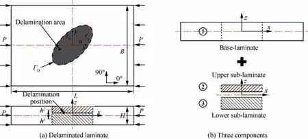
Fig. 1 Geometric model of a laminate with an elliptical delamination.
Taking the typical elliptical delamination problem22shown in Fig.1(a)as an example,the dimension of the rectangular composite laminate is 150 mm(L)×100 mm(B)×4 mm(H).The stacking sequence is [45/0/-45/90]4S, and material parameters have been listed in Table 1, in which E11and E22are elastic moduli in the 0° and 90° directions, G12and G13are shear moduli, ν12is the poisson’s ratio, Xtand Xcare the tensile and compressive strength in the fiber direction, Ytand Ycare the tensile and compressive strength in the in-plane transverse direction,S12are the shear strength,GICand GIICare the critical energy release rate of the opening and shearing mode,other parameters related to the through-thickness direction are set based on the transverse isotropic assumption and engineering experience. An elliptical delamination is embedded at the center of the laminate. The semi-major and -minor axes of the elliptical delamination are defined as raand rb, respectively. The direction of the ellipse is determined with an angle α,which is between the global x axis and the major axis of the ellipse,and ΓDis the delamination boundary.h2(or h3)is the distance between the mid-planes of the Base-laminate and the Upper sub-laminate (or the Lower sub-laminate). Clamping constraints are applied to the upper and lower loading edges of the laminate, and only out-of-plane translational degree of freedom of the side edges are constrained,22–26a uniaxial compressive loading P is applied along the x axis.
According to the method in Ref.[22],the laminate is subdivided as three separate components,10,12,26i.e. the baselaminate, the upper (thinner) sub-laminate, and the lower(thicker) sub-laminate, which are numbered as component 1–3 in Fig. 1(b), respectively. When the boundary conditions for the above problem are mathematically given, following the analytical model in Ref. [22] and on the basis of the Rayleigh-Ritz methodology,6,7,14,15,27the deformation fields can be expressed with a series of functions with pending coefficients Kmn(m,n=0,1,2···), and the strain energy of each component can be integrated. Then with the summation of the strain energy of the three components, the total strain energy U of the whole laminate in Fig. 1(b) can be given, as expressed in Eq. (1):


Table 1 Composite material properties.
where Uiis the total strain energy of the ithcomponent. The total potential energy Π of the composite laminate can be defined as the summation of the strain energy U and external work W:

Actually, following the Rayleigh-Ritz methodology, the total potential energy of the laminate Π is eventually a function of all the pending parameters Kmn.According to the principle of minimum potential energy, the deformation field and buckling state can be all determined when a series of partial differential equation are solved,10as given in Eq. (3), and the conservative buckling process of the laminate can be therefore computed step by step.

2.2. Non-conservative part—delamination propagation path and failure evaluation
In consideration of the complicated delamination boundaries when delamination has propagated, an innovative method has been proposed in the precious work22based on the segmentation and approximation idea of definite integration.Based on this method, the delamination area is divided into n strips, as shown in Fig. 2, and the delamination boundary can be approximately substituted by boundaries of all strips,which have been highlighted in yellow. Then the shape function ΓD(x,y) of the delamination boundary can be described with a set of equations of all strips. Taking the ithstrip as an example, the shape function can be written as:
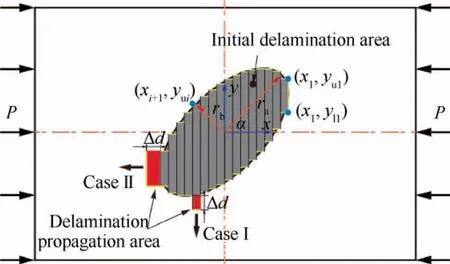
Fig. 2 Calculation diagram of delamination propagation path.

where the coordinates at the far right and left boundaries of the outer two strips are set as x1and xn+1, the coordinates at the upper and lower boundaries of the ithstrip are set as yuiand yli.With the use of this strategy and simultaneously taking the delamination propagation position and direction into account, two delamination propagation cases are considered,including the transverse propagation case(Case I)and longitudinal propagation case (Case II), as shown in Fig. 2.
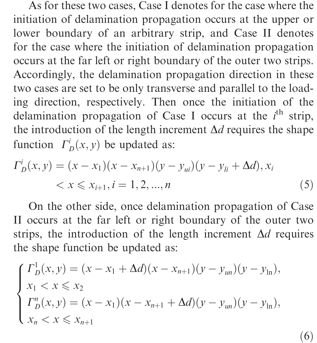
Following this method,the new delamination boundary can be determined no matter where the delamination propagation occurs, and the total potential energy Π of the laminate can be updated step by step. Further, according to the mechanics of brittle fracture, when the energy release rate G at any point at the delamination boundary has reached its critical value,the initiation of delamination propagation would occur,5,8,17,27–29and Eq. (7) provides its mathematical expression, in which G is calculated through a partial differentiation equation of the total energy Π and the delamination area A.It is worth noting that the participation of each delamination propagation mode cannot be determined by Eq. (7), and GC= GICis assumed in this work to obtain conservative results.18,22

After the initiation of delamination propagation, actually the external force would gradually decrease with the continuously growth of the delamination, at a constant deformation extent. Therefore the ultimate failure of the laminate can be defined according to the recommendation in the engineering practice. In this model, the laminate is considered as failed when a load drop of over 20%18,22has been detected in the iteration procedure,as shown in Eq.(8), and then the calculation process is ended.

2.3. Model implementation
Fig. 3 shows the calculation process of the analytical model,and the flowchart mainly comprises the following several steps:
Step 1: Input basic geometric data of the composite laminate, and suppose the functions of the deformation fields on the basis of the boundary conditions and the FSDT.
Step 2:Calculate the total energy of the laminate,and solve the partial differential equations.
Step 3:Compute the strain energy release rate at the delamination boundaries. If Eq. (7) has been satisfied at any point,go to Step 4; otherwise increase the deformation extent with an increment Δε and go back to Step 1, then update the functions of deformation fields.
Step 4: Calculate the external force of the laminate, and compare it with the maximum value. If the force drop was within 20%, add a length increment Δd to the initial length of the strip where delamination propagation occurs, then go back to Step 1 and update the functions of deformation fields;otherwise end the simulation procedure directly.
Additionally,simultaneously taking the computational cost and accuracy of the model into consideration, corresponding parameters are set as Δε = 10-4, n=40, and Δd=1 mm.
3. Computational and experimental cases
On the basis of the previously developed and validated analytical model, a series of computational cases are established for the investigation on the effects of delamination parameters,and experiments for some typical cases are additionally conducted for the further validation of the analytical model. This section introduces the setups of the cases.
3.1. Computational cases
To comprehensively reveal the effects of parameters including the depth, direction, aspect ratio, and area of an elliptical delamination on the compressive buckling,delamination propagation,and failure behaviors of composite laminates,a series of computational cases are designed and listed in Table 2. In Table 2, the depth d represents the position of the delamination in the thickness direction, and it is defined as the ratio of the thickness of the upper sub-laminate and the whole laminate.α,ra,and rbare the geometric parameters of the elliptical delamination.The aspect ratio is defined as λ = ra/rb,and the delamination area is calculated with Eq. (9).
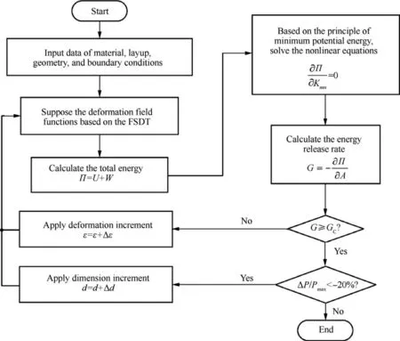
Fig. 3 Calculation process of analytical model.

The cases in Table 2 are mainly comprised of four categories:
Cases d1-d3: These three cases are designed for the investigation on effects of the delamination depth. Same geometric parameters: α=0°, ra=25 mm, rb=12.5 mm, and A=981.75 mm2are designed for these cases, and delaminations are all located at the interface between the 0° and-45°plies. The only difference is that, the delamination is set between the 6th and 7th plies for Case d1, between the 10th and 11th plies for Case d2, between the 14th and 15th plies for Case d3.
Cases α1-α5: These five cases are designed for the investigation on effects of the delamination direction. Same delamina-tion depth (14/32)and parameters:ra=25 mm,rb=12.5 mm,and A=981.75 mm2are designed for these five cases, and delaminations are all located at the interface between the 0° and-45° plies. The only difference is that,the elliptical delamination direction α is set as 0°, 30°, 45°,60°, and 90°, respectively.

Table 2 Computational cases with different delamination parameters.
Cases λ1-λ4:These four cases are designed for the investigation on effects of the delamination aspect ratio. Same delamination depth (14/32), direction α=0°, and semi-major axis ra=25 mm are designed for these four cases.The only difference is that the semi-minor axis of the elliptical delamination is set as rb=10 mm, 12.5 mm, 16.7 mm, and 25 mm, respectively. Therefore the aspect ratios of the elliptical delaminations are 2.5, 2.0, 1.5, and 1.0, respectively.
Cases A1-A4: These four cases are designed for the investigation on effects of the delamination area.Same delamination depth (14/32), direction α=0°, and circular shape (with an aspect ratio of 1.0) are designed for these four cases. The only difference is that the semi-major and semi-minor axes of the elliptical delamination are set as ra=rb=25 mm, 20 mm,15 mm, and 10 mm, respectively.
3.2. Experimental cases
To validate the effectiveness and accuracy of the developed analytical model, failure behaviors of Case α3has been experimentally analyzed in Ref. [22], according to ASTM D7137.30In this work,following the same experimental procedures as in Ref.[22]and simultaneously considering the cost,specimens of typical cases including Cases λ3,A1,A3,and A4have been also manufactured, and three specimens were tested for each case.Failure loads were recorded by the test system. With the further comparison of experimental and computational results of these additional four cases, the applicability of the analytical model for a more wide range can be simultaneously validated.
4. Results and discussion
Results of the computational and experimental cases are given in Table 3 and analyzed in this section, effects of the elliptical delamination depth, direction, aspect ratio, and area on the buckling process,delamination propagation and failure behaviors of delaminated composites are comprehensively discussed,and basic evaluation principles of delamination damage have been concluded.
4.1. Effects of the delamination depth d
As shown in Table 3, by comparing the predicted results of Cases d1-d3, it can be clearly seen that all the local / global buckling and failure loads slightly increase with the delamination depth moving from a shallow position to the deep. As is concluded in Refs.[18,22],the deformation process of a delaminated composite under compression can be divided into three stages:the original in-plane deformation stage,the local buckling stage, and the global buckling stage. The demarcation point of the first two stages presents the local buckling load,at which the upper sub-laminate starts to buckle;the demarcation point of the latter two stages presents the global buckling load, at which the lower sub-laminate also starts to buckle.When the delamination is at a shallow position, the stiffness of the upper sub-laminate is relatively low, which can lead to its premature local buckling. When the sub-laminate starts to buckle,its axial stiffness would suffer a sudden loss23,31,32then eccentric compressive loading would generate, which can lead to an increasingly faster growth of the out-of-plane deflection,which would result in premature global buckling and failure.This can be taken as support of the variation trend of the predicted buckling and failure loads in Table 3.
Fig. 4 shows the energy release rate distributions along delamination boundaries in the three cases, corresponding to the loads at which the delamination propagation initiates. In Fig. 4, the delamination area is marked with a black dotted loop, the blue, green, and purple loops are the energy release rate distributions along the delamination boundaries, and the threshold G=GICis reached at the Maximum Point (MP) in each loop. The point ‘MP’ and centre point ‘O’ determine an red connection line with an intersection angle θ to the x direction. The red points ‘PP’ (Propagation Point, shows the position where the delamination propagation initiates) are intersection points of the connection line and the delamination boundary.Besides,the black arrows marked out the delamination propagation direction, indicating that the delamination tends to propagate transversely to the load. From Fig. 4, it can be seen that for a shallow delamination case with a more premature and larger out-of-plane buckling deformation,such as Case d1, the blue energy release rate distribution loop is more full, i.e. the difference between the maximum and mini-mum value in the loop is relatively small. Therefore in some extreme terms, such as more shallow delamination cases, it is possible that the delamination would propagate in the load direction. Comparatively, for cases with deep delaminations,the difference between the maximum and minimum value in the loop is larger, indicating that the delamination tend to propagate only transversely to the load direction.
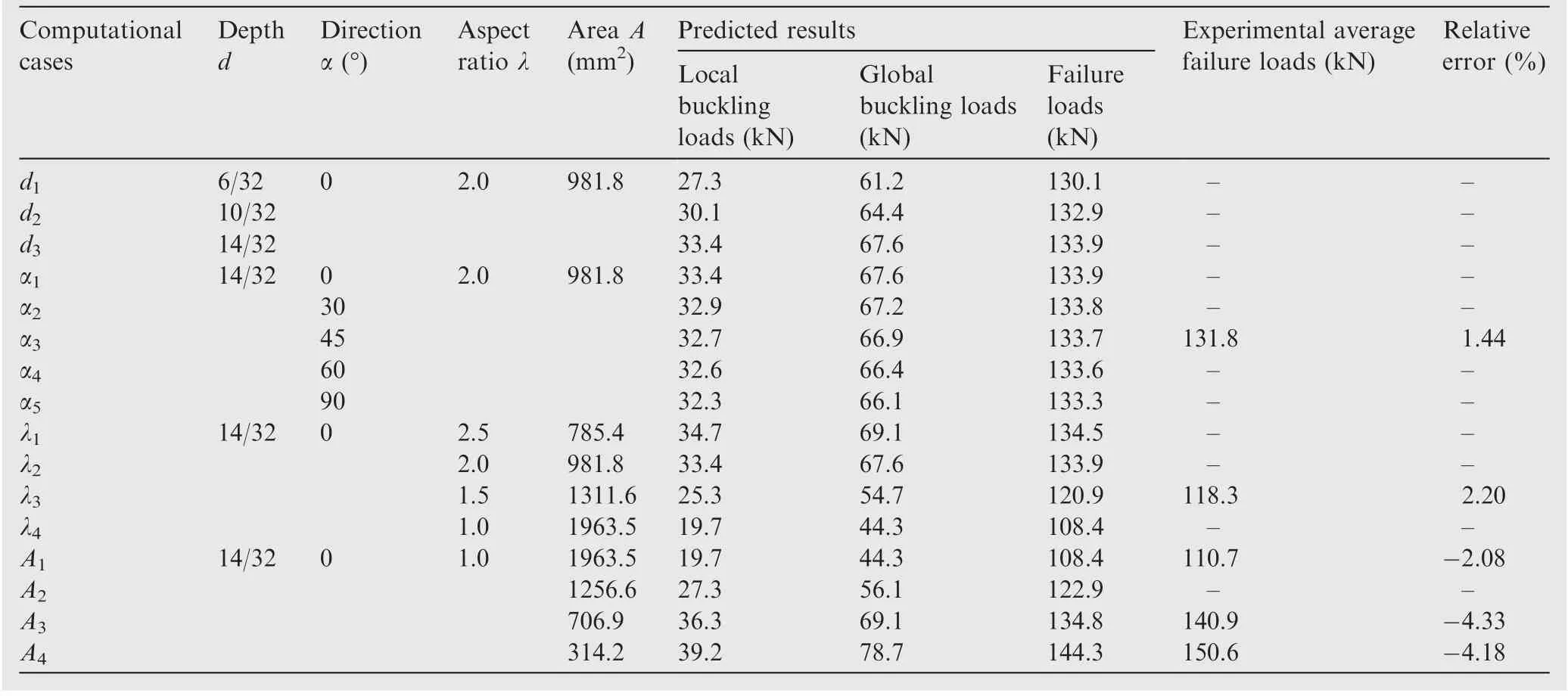
Table 3 Buckling and failure loads of cases with different delamination cases.
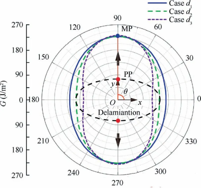
Fig. 4 Energy release rate distribution along delamination boundary: Case d1-d3.
4.2. Effects of the delamination direction α
In Table 3, by comparing the predicted results of Cases α1-α5with different delamination directions,it can be seen that with the change of delamination direction α from 0° to 90°, all local/global buckling and failure loads show a slow downward trend,and the declining extent is within 4%.Therefore conclusions can be found that when other parameters are kept constant, only delamination direction has little effect on the buckling and failure loads of delaminated composites.Besides,when the delamination direction is consistent with the loading direction, the laminate would have the highest buckling and failure loads.
The energy release rate distributions along the delamination boundaries in Cases α1, α2, α4, and α5, corresponding to the propagation initiation load are presented in Fig. 5, whilst the result of Case α3has been given in Ref. [22]. Similar to Fig.4,the delamination areas,energy release rate distributions along the delamination boundaries, maximum points ‘MP’,initial delamination propagation positions ‘PP’ and directions θ are all given.With the rotation angle α increasing from 0°to 90°, it can be found that the energy release rate distribution loop is increasingly full, but delaminations still tend to propagate transversely.Meanwhile,it can be also found that for the four cases, directions of energy release rate loops are also rotating with the changing of α, and the propagation points‘PP’are all near to the points in delamination boundaries with the maximum transverse (y) coordinates, which is in accordance with the results in Ref. [22]. The comparisons of directions where the ‘PP’ in Fig. 5 belongs (θ) and directions of points with maximum transverse coordinates (η) in delamination boundaries are all listed in Table 4. It can be clearly seen that these two directions are approximately equal,and the relative errors between them are all within 4%, which indicates that the initiation of the delamination propagation is mostly possible to occur at the boundary points with the maximum transverse coordinates,9,17,18,22for the arbitrary elliptical delamination problems investigated here.
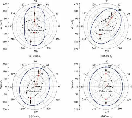
Fig. 5 Energy release rate distribution along delamination boundary (Case α1, α2, α4, α5).
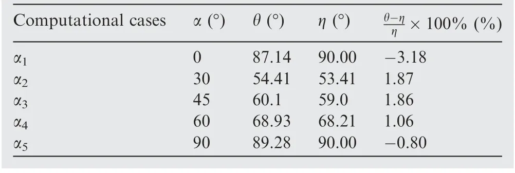
Table 4 Comparisons of directions of initial delamination propagation points (θ) and directions of the points in delamination boundaries with the maximum transverse coordinates(η).
4.3. Effects of the delamination aspect ratio λ
As shown in Table 3,comparing the predicted results of Cases λ1-λ4with different aspect ratios, it can be seen that with the change of delamination aspect ratio from 2.5 to 1.0, all local/ global buckling and failure loads apparently decrease, and the maximal declining extents of these three loads is 43.2%,35.9%, and 19.4%, respectively. Therefore delamination aspect ratio has remarkable influence on the buckling and failure loads of delaminated composites. When rais fixed, buckling and failure loads of delaminated laminates vary in a same trend with the delamination aspect ratio.
Fig.6 also shows the energy release rate distributions along the delamination boundaries in the four cases, corresponding to the propagation initiation load. It can be clearly seen that the energy release rate distribution loop is also increasingly full with the decrease of the aspect ratio, and as for Case I, the minimum value even approximately equals to the maximum value in the loop. Therefore, combining with the conclusions in Section 4.2, when the major axis of an elliptical delamination is along the loading direction,delaminations tend to propagate transversely. But when the aspect ratio is small enough,there is also a possibility of the delamination to propagate in the loading direction.
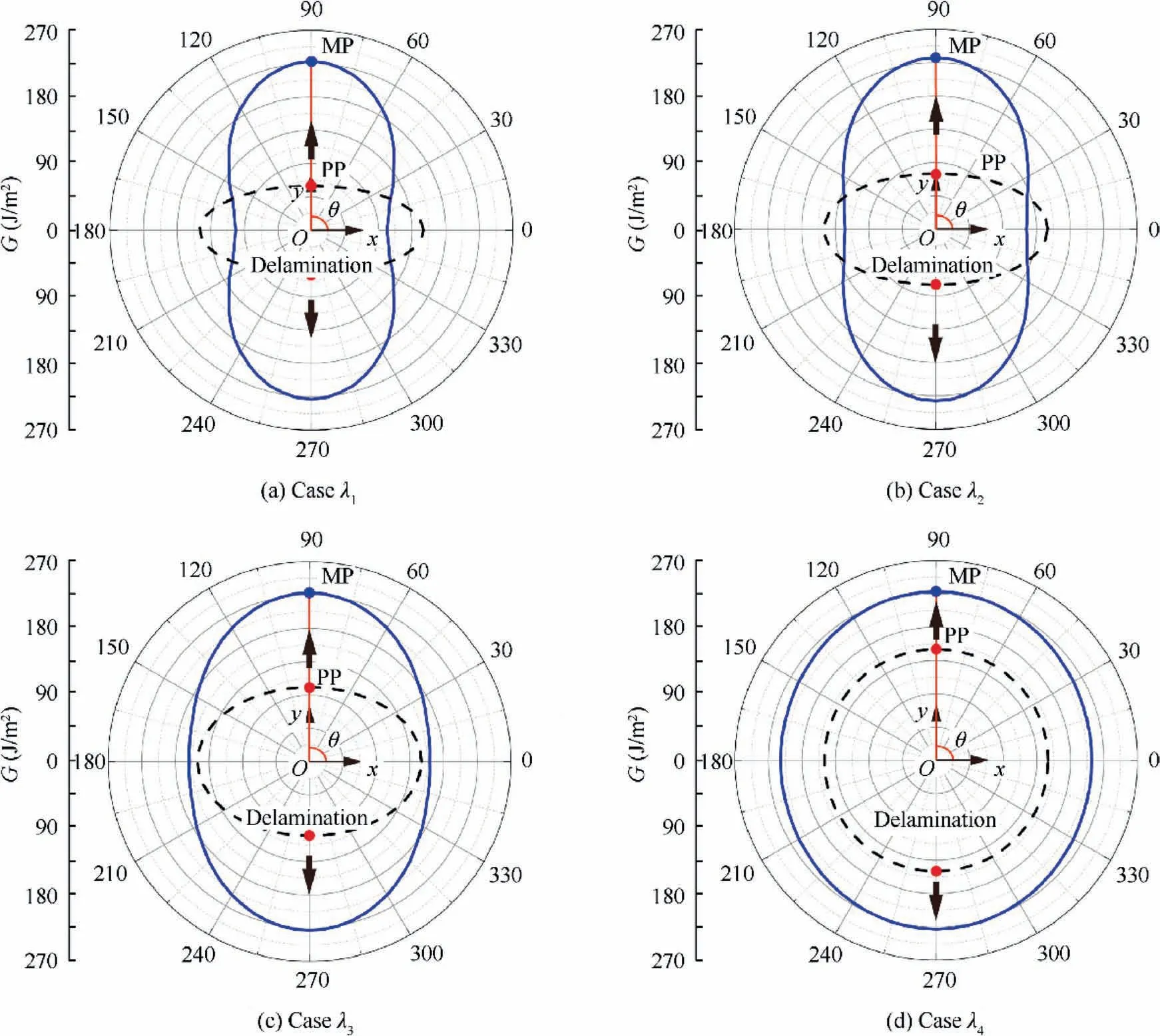
Fig. 6 Energy release rate distribution along delamination boundary (Case λ1-λ4).
4.4. Effects of the delamination area a
In Table 3, by comparing the predicted results of Cases A1-A4with different delamination areas. With the change of delamination radius from 10 mm to 25 mm,all local/global buckling and failure loads decrease much more apparently,and the maximal declining extents of these three loads is 49.7%,56.3%,and 24.9%, respectively. Therefore the delamination area also has remarkable influence on the buckling and failure loads of delaminated composites, buckling and failure loads of delaminated laminates vary inversely with the delamination area.
Fig. 7 illustrates the energy release rate distributions along the delamination boundaries in the four cases, corresponding to the propagation initiation load. It can be clearly seen that the energy release rate distribution loop is also increasingly full with the delamination area,indicating that for a larger circular delamination, there is also a possibility of the delamination to propagate in the loading direction.
Additionally,it is worth noting that in all cases,the delamination propagation processes were all fast and directly led to failures of composite laminates.22As for typical Cases α3, λ3,A1, A3, and A4, the predicted failure loads all agree very well with experimental average values, and the relative error are all within 5%, validating the effectiveness and accuracy of the analytical model.
4.5. Evaluation principles of delamination damage
Combining the predicted results of delamination cases with different depths,directions,aspect ratios,and areas in Sections 4.1–4.4, as for composite laminates investigated in this work,basic principles can be concluded as follows,
1) Delamination depth and directions have little effect on the buckling and failure loads of composite laminate;
2) The fast delamination propagation process is the direct cause of failures of composite laminates;
3) The initiation of the delamination propagation occurs at delamination boundary points with the maximum transverse coordinates, and delamination tends to propagate transversely to the loading;
4) Compared to the delamination depth and direction, the aspect ratio and area of an elliptical delamination are the most important factors affecting the buckling and failure loads of delaminated composites.
Further in this work, when studying on the effects of aspect ratios with Case λ1-λ4, the delamination area is also a variable. Besides, in Case A1-A4, the buckling and failure loads dropped remarkably with the increase of delamination area, whilst the aspect ratio is constant. Therefore the key factor affecting buckling and failure loads of delaminated composites tend to be the maximum dimension raor the area A of a delamination.
Fig.8 illustrates variation trends of the buckling and failure loads with the maximum dimension raor the area A of delaminations in all cases, respectively. In Fig. 8(a), it can be found that for Cases A1-A4, the buckling and failure loads show approximate linear growth with the maximum dimension ra.However, as for all other cases with a maximum dimension ra=25 mm, it is obvious that the factor rahas lost its ability to measure the buckling and failure loads. On the other hand,in Fig. 8(b), although the load data of Cases d1-d3and α1-α5slightly floats due to changes of delamination depth or direction, generally, the local / global buckling and failure loads of all cases show clear linearity with the delamination area A, and the linear Pearson’s correlation coefficients r are-0.9672, -0.9672, and-0.9405, respectively. Therefore above all,the most important principle is that,it is the delamination area A that truly affecting the buckling and failure loads of delaminated composites. This significant conclusion indicates that,with the analytical model in this work,the buckling and failure loads of delaminated composites can be approximately evaluated only with the delamination area,regardless of the delamination depth, direction, and aspect ratio. It has important guiding significance and can be taken as basic evaluation principles for engineering practice,because delamination issues with complicated shapes can be directly simplified as circular delaminations with equal areas.
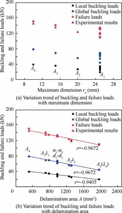
Fig. 8 Variation trends of buckling and failure loads with key factors.
5. Conclusions
In this paper,an analytical model is implemented based on the FSDT and the mechanical theory of brittle fracture. The model innovatively considers both the conservative buckling process and non-conservative delamination propagation and failure process of delaminated composites subjected to uniaxial compression loads.Focusing on the most typical and representative elliptical delamination issue, various of computational cases are established and the effects of geometrical delamination parameters including the delamination depth, direction,aspect ratio, and area on the buckling, delamination propagation, and failure behaviors of composite laminates are thoroughly analyzed. Based on the results, basic evaluation principles are concluded:
(1) The delamination depth and direction only have slight effects on the buckling and failure loads of composite laminates, but the delamination direction would affect the initial delamination propagation position.
(2) The initiation of the delamination propagation occurs at points with the maximum transverse coordinates in the delamination boundary, and delamination tends to propagate transversely to the loading.
(3) The delamination area is the key factor that truly affecting the failure behaviors of delaminated composites,and the local/global buckling and failure loads show clear linearity with the delamination area. It has significant guidance for the evaluation of delamination damage tolerance in engineering practice, because delamination problems with complicated shapes can be directly simplified as circular delaminations with equal areas.
Declaration of Competing Interest
The authors declare that they have no known competing financial interests or personal relationships that could have appeared to influence the work reported in this paper.
Acknowledgements
The research work is supported by the National Science Foundation of China (Nos.11572058, 11772028, 11872131 and U1864208).
 CHINESE JOURNAL OF AERONAUTICS2021年7期
- CHINESE JOURNAL OF AERONAUTICS的其它文章
- Integrated batteries layout and structural topology optimization for a solar-powered drone
- Polynomial networks based adaptive attitude tracking control for NSVs with input constraints and stochastic noises
- Morphing wing flaps for large civil aircraft:Evolution of a smart technology across the Clean Sky program
- Review on bio-inspired flight systems and bionic aerodynamics
- SARISTU:Adaptive Trailing Edge Device(ATED)design process review
- Continuous morphing trailing-edge wing concept based on multi-stable nanomaterial
