Aeroelastic prediction and analysis for a transonic fan rotor with the ‘‘hot” blade shape
Di ZHOU, Ziling LU,*, Tongqing GUO, Guoping CHEN
a Key Laboratory of Unsteady Aerodynamics and Flow Control, Ministry of Industry and Information Technology, Nanjing University of Aeronautics and Astronautics, Nanjing 210016, China
b State Key Laboratory of Mechanics and Control of Mechanical Structures, Nanjing University of Aeronautics and Astronautics, Nanjing 210016, China
KEYWORDS Energy method;Fan rotor;Flutter;Running blade shape;Static aeroelasticity;Time-domain method
Abstract This paper focuses on aeroelastic prediction and analysis for a transonic fan rotor with only its‘‘hot”(running)blade shape available,which is often the case in practical engineering such as in the design stage.Based on an in-house and well-validated CFD solver and a hybrid structural finite element modeling/modal approach, three main aspects are considered with special emphasis on dealing with the‘‘hot”blade shape.First,static aeroelastic analysis is presented for shape transformation between ‘‘cold” (manufacturing) and ‘‘hot” blades, and influence of the dynamic variation of‘‘hot”shape on evaluated aerodynamic performance is investigated.Second,implementation of the energy method for flutter prediction is given and both a regularly used fixed‘‘hot”shape and a variable ‘‘hot”shape are considered. Through comparison, influence of the dynamic variation of‘‘hot” shape on evaluated aeroelastic stability is also investigated. Third, another common way to predict flutter,time-domain method,is used for the same concerned case,from which the predicted flutter characteristics are compared with those from the energy method.A well-publicized axial-flow transonic fan rotor, Rotor 67, is selected as a typical example, and the corresponding numerical results and discussions are presented in detail.
1. Introduction
With the development of modern aero-engines, the pursuit of high-performance compressor and fan rotor has become increasingly intense.1Particularly in terms of blade design,many advanced means have been taken, such as optimization of blade profile,extensive application of light flexible materials and thin-walled structures and cancellation of additional mechanical dampers like part-span shrouds. Although they bring advantages of superior rotor overall performance and light weight, however, the accompanying aeroelastic problems(static aeroelasticity and flutter)may become more prominent,which are firmly related to interactions between aerodynamic loads and structural motions. With a rapid development of Computational Fluid Dynamics (CFD) and Computational Structural Dynamics (CSD) techniques, much attention has been paid to numerical investigation of rotor blade aeroelasticity.
In the study of static aeroelasticity, two distinct rotor blades are often introduced:one has a‘‘cold”(manufacturing,unloaded) shape and the other one has a ‘‘hot” (running,loaded) shape. Due to the aerodynamic and centrifugal loads acting on the blade under running conditions, there exist differences between two shapes, which can be much significant for flexible structures. As shown in previous literatures, any variations of geometrical parameters such as stagger angle,2sweep and lean,3casing treatment4tip gap size5may have dominant effects on the aerodynamic characteristics, thus accurate prediction of static aeroelasticity is of great importance. Also it will be seen below that shape transformation between ‘‘cold” and ‘‘hot” blades is usually a prerequisite of flutter prediction. Depending on the specific objective in engineering, static aeroelastic studies are classified into two categories. The first is to determine the ‘‘hot” shape from a given‘‘cold” one, which serves as a necessary step for checking the running blade geometry and design performance under the nominal condition. For example, Yamamoto and August6combined a finite element structure code and a finite difference Euler solver to investigate the effects of blade deformation on the performance of a large-scale propfan. Wilson et al.2adopted a closely-coupled aeroelastic code to predict the blade untwist and specially study the effect of stagger variability for a transonic fan rotor. Later, with a similar technique, Hazby et al.7studied the effects of blade deformation on the performance of a transonic impeller.It was found that the differences vary a lot with operating conditions and were mainly due to the tip clearance variation. More recent work can be referred to Wang,8Kang9and Falissard et al.10The other category of static aeroelastic studies is just the opposite, which can be used to guide the manufacturing and assembly process.On this issue, Mahajan and Stefko11proposed an iterative multidisciplinary analysis for accurate ‘‘cold” shape determination of a ducted fan rotor blade by coupling several commercial solvers.Yang and Zheng12reported an iterative procedure for the unrunning design of rotor blades. The numerical results for a ducted hollow fan showed a fully three-dimensional (3D) feature of the stagger angle and the significant effects of aerodynamic loads on deformation of the swept and bowed blade shape. Timon and Corral13used a simple spring-mass model to study the effects of geometric nonlinearities on the ‘‘hotto-cold” transformation of compressor blades, however the aerodynamic forces were discarded in their work. Some other interesting work include those of Liu14and Gaun et al.15
For the blade flutter,a large number of prediction methods at different levels of fidelity have been proposed in the past decades, among which the energy method and the timedomain method have gained the most popularity due to their advantages of making full use of the advances in CFD. The energy method prescribes that blades vibrate in a motion of some natural modal around its equilibrium (loaded) position,and then analyzes aeroelastic stability from the total aerodynamic work per cycle of vibration done by unsteady aerodynamic forces. Using this method, most earlier flutter analysis were aiming at 2D cascade and a comprehensive review can be found in Ref. [16]. In an innovative study by He and Denton,17a 3D shape correction method of solving the Euler equations and thin-layer Navier–Stokes (N–S) equations was developed, which was applied to an inviscid flat plat cascade and a real fan rotor.Sanders et al.18investigated the stall flutter features of a transonic low-aspect ratio shourdless fan blisk using a CFD code of solving the RANS (Reynolds-Averaged Navier–Stokes) equations. The effects of tip clearance, vibration amplitude and physical-time-step-size on flutter prediction were studied.With a similar technique, Vahdati et al.19identified two types of flutter, namely, stall flutter and acoustic flutter,which are found to be driven by flow separation and intake acoustics, respectively. Recently, the authors20reported a double-passage shape correction based energy method for predictions of unsteady flow and flutter in turbomachinery,which shows a favorable convergence speed and solution stability.
Compared with the energy method, time-domain method provides a stronger fluid–structure coupling and a more actual modeling because the assumptions of blade forced vibration and linear flutter behavior are removed, however, it is usually at the cost of higher complexity and computational efforts.For this method, at each time step, the structural motion of blade relative to its unloaded position is calculated from the unsteady aerodynamic and centrifugal forces and then the instantaneous flow filed is simulated based on the updated configuration. To accord with its theoretical basis, the timedomain method needs to be applied for a‘‘cold”shape,which is different from the energy method.So far,great contributions have been made in developing various time-domain methods.For example,Carstens and Belz21studied flutter characteristics of vibrating compressor blades with an algorithm combining the Newmark integration method and an Euler upwind solver.Sadeghi and Liu22coupled an unsteady RANS solver with a modal approach to perform the flutter analysis of Rotor 67 at design speed.Later,Zheng and Yang23and Hongsik et al.24also studied flutter characteristics of the same fan rotor with different time-domain methods, both of which indicate that the flow unsteadiness is a key factor to influence the aeroelastic stability.Note that in all of their work,there seems no mention of the used blade shape or the associated shape transformation, despite the fact that the publicized profiles of Rotor 67 actually represent the ‘‘hot” blade geometry under a design speed operating condition as stated in the original report.25
Given the statements above, this study is motivated by the following concerns.First,in order to obtain the fan rotor performance map, most existing studies are based on steady flow computations for a fixed ‘‘hot” shape. As pointed out by Wilson et al.,2this common practice could produce significantly different results relative to those for a variable ‘‘hot” shape,which is gained from a ‘‘cold” shape by ‘‘cold-to-hot” static aeroelastic prediction. However, it is often the case that only a ‘‘hot” shape under a certain operating condition is available such as in the design stage (no manufacturing blade is available). Here, we consider this issue not only for showing an effective solution procedure and static aeroelastic analysis,but also making a necessary basis for the flutter prediction.The second concern is similar to the first one, that is, when using the energy method to evaluate aeroelastic stabilities under different operating condition, the usual way is to make calculations for an oscillating blade around a fixed equilibrium position (i.e., a fixed ‘‘hot” shape). Obviously, this treatment also ignores the dynamic variation of‘‘hot”shape.How much influence does this simplification has on flutter characteristics have not yet been investigated. The third concern is about comparison of the energy method and time-domain method.To make reasonable flutter predictions with either method,care should be taken to use an appropriate blade shape.However, to authors’ knowledge, most studies did not address this issue specially. Therefore, taking the aforementioned case as a typical example where only a ‘‘hot” shape is available, implementations of each method are presented and their results are compared.
This paper is organized as follows.First we introduce basic numerical simulation methods in CFD and CSD solvers. Section 3 gives the geometry and computational model.Then Sections 4 and 5 are about static aeroelastic and flutter predictions for a transonic fan rotor with the ‘‘hot” blade shape, respectively. Discussions and analysis on the solution procedures and calculated results are together presented with emphasis on resolving the above three concerns. The last section is the conclusion.
2. Basic numerical simulation methods
2.1. CFD solver
An in-house and well-validated CFD solver20,26is used for simulation of 3D steady and unsteady flows around rotor blades so as to provide accurate aerodynamic forces, which is based on solving the RANS equations in a rotating frame of reference. For simplicity, the rotation axis is assumed to coincide with the x-axis and the angular velocity vector ω has the components ω= [ω,0,0]T.Written in an integral form for a control volume Ω(static or deforming)with a surface element dS, the N–S equations read

Because the present governing equations are solved for the absolute velocities,vectors of the conservative variables W,the convective fluxes Fcand the source terms Q have the following components
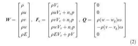
where ρ, u, v, w, p, E denote the density, the velocities,the pressure and the total energy per unit mass, respectively.The absolute and relative contravariant velocities are defined as V=nx(u-ug)+ny(v-vg)+nz(w-wg) and Vr=V+nyωz-nzωy, with nx, ny, nzbeing components of the outward facing unit normal vector of the surface ∂Ω and ug, vg, wgcomponents of the grid velocity vector. For steady flow simulation,the grid velocities are set to zero.The viscous fluxes Fvretain the same as in the Navier–Stokse equations formulated in an inertial frame, which are not shown here.
A structured finite volume method is used to discretize the governing equations, with the convective fluxes evaluated by Roe’s flux-difference splitting scheme and the viscous fluxes by central difference scheme. To achieve higher accuracy, a third-order Monotone Upstream Centered Scheme for Conservation Laws (MUSCL) scheme with the Van albada’s limiter is employed for the solution reconstruction. For steady flow simulation, an implicit Lower-Upper Symmetric Gauss-Seidel (LUSGS) scheme is used to integrate equations in time. For unsteady flow simulation, the dual time-stepping approach is applied together with the LUSGS scheme for the stationary solution in pseudo time. The turbulence effects are accounted for by the Spalart–Allmaras (S–A) oneequation model. To accelerate the solution convergence, the Message Passing Interface (MPI) technique is used for parallel programming.
At the inlet, the total pressure, total temperature and flow angles are prescribed, while the other flow variables are calculated from the non-reflect boundary conditions and the isentropic relation. At the outlet, with the static pressure specified at hub location, the pressure distribution is obtained by solving the radial equilibrium equation, and the other flow variables are extrapolated from the interior field. At wall surfaces, the no-slip and adiabatic boundary conditions are used.Without considering the inter-blade phase angle,periodic conditions are imposed along the circumferential boundaries. In aeroelastic computations, to achieve the mesh deformation with high quality and efficiency, a recently-developed hybrid dynamic mesh method namely the RBF-TFI method27is applied. Specially, when dealing with blade tip clearance, to prevent large mesh distortion and meanwhile keep the shape of casing unchanged, the mesh points are allowed to slide along the casing surface.
2.2. CSD solver
Applying Lagrange’s equations to a rotating elastic blade, the structural equation of motion in physical space can be written as

where Δx is the displacement vector relative to the ‘‘cold”shape xcold, m, g, k represent the mass matrix, the damping matrix and the dynamic stiffness matrix respectively, fc, fg, farepresent vectors of the centrifugal force, Corilios force and aerodynamic force respectively. The influence of fgis very small and it is often ignored. By decomposing the total deformation Δx into two parts: one is the centrifugal force caused deformation Δxcand the other one is the aerodynamic force caused deformation Δxa, Eq. (3) turns to

Due to the fact that Δxais very small compared to the characteristic length of rotor blade,its influence on g,k and fccan be ignored. Therefore, we have

where Δxcis regarded as the deformation relative to xcoldand is obtained from the nonlinear finite element analysis of structures.

Subtracting Eq. (5) from Eq. (4), we obtain By defining an only centrifugal force caused blade shape(also named the ‘‘vacuum” shape) as xvac=xcold+Δxc, Δxacan be regarded as the deformation relative to xvac.For solving Eq. (6), the linear elastic model is usually assumed, based on which the modal superposition method is most adopted. With the first n vibration modals included, Δxais expressed as

where Φ is the structural modal shape matrix with φithe ith vector, and q is the vector of the generalized (modal) coordinates with qithe ith component.
Substituting Eq.(7)into Eq.(6)and multiplying both sides by ΦT, the structural motion of equation is transformed into the modal space as follows
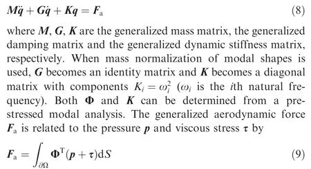
A second-order predictor–corrector scheme28is applied to solve Eq. (8) for the solution q and the resulting Δxa. This method has an overall good performance in computational accuracy, efficiency and stability, which is beneficial to enable a tight CFD/CSD coupling. Because it is usually not desirable to generate the point-to-point mesh at the fluid–structure interface, for accurate data exchange between fluid and solid domains, the Radial Basic Function (RBF) method is employed to interpolate the displacement or modal shape from structural nodes to aerodynamic mesh points.
Note that for static aeroelastic computations, the inertial and damping forces disappear in all the above structural equations and the aerodynamic force becomes independent of time.
3. Geometry and computational model
A well-publicized axial-flow transonic fan rotor, Rotor 67, is selected to be studied, which was designed and experimentally studied at the NASA Lewis Research Center.25For this rotor,different from most existing studies, we consider the dynamic variation of ‘‘hot” shape at different design speed operating conditions, and the provided blade profiles, tip clearance and other geometry parameters are all reasonably assumed as the ones at the peak efficiency condition. A schematic diagram of the rotor together with the computational domain is shown in Fig.1,and the basic specifications are given in Table 1.For structural modeling,the material of the solid blade is chosen as titanium-alloy and the hub is thought to be rigid enough.Like in most numerical studies,the structural damping is omitted so that the damping matrices g and G vanish.
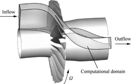
Fig. 1 Schematic diagram of Rotor 67.
In the fluid domain, the mainstream region and tip clearance are meshed using typical O4H and OH topologies respectively and the resulted whole mesh consists of 0.74 million cells.This mesh has proven to be fine enough with a previously conducted mesh-independence study.The inlet flow is assumed to be uniform and along the axial direction, which has a total pressure of 1.013 MPa and a total temperature of 288.15 K.At the outlet, by adjusting the prescribed static pressure at hub within an appropriate range, different operating conditions can be realized. The unit Reynolds number based on the inlet velocity is about 1.2×10⁷m-1. In the solid domain, 8-node solid hexahedron elements are used for Finite Element Method(FEM) analysis, resulting in a mesh consisting of 1600 cells.The first six natural modals are considered.
In order to achieve our goals,three main tasks will be considered in the next two sections.First,static aeroelastic prediction is performed in order to obtain an accurate‘‘cold”shape,from which geometry differences among ‘‘cold”, ‘‘vacuum”and ‘‘hot” shapes and aerodynamic characteristic differences between fixed and variable‘‘hot”shapes are discussed.Second,using the energy method to predict blade flutter, differences between aerodynamic dampings from fixed and variable‘‘hot”shapes are analyzed,so that influence of the dynamic variation of‘‘hot”shape on flutter characteristics is explored for the first time to our knowledge. Last, comparisons of the energy method and time-domain method are made in terms of prediction accuracy.
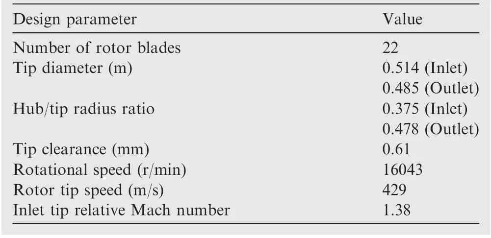
Table 1 Basic specifications of Rotor67.
4. Geometry and computational model
4.1. ‘‘Cold-to-hot” and ‘‘hot-to-cold” transformation algorithms
Because evaluation of the centrifugal deformation Δxcand pre-stressed modal analysis depend on a ‘‘cold” blade shape that is not known a priori, a ‘‘hot-to-cold” transformation is required. Before introducing its algorithm, we would like to first give the ‘‘cold-to-hot” transformation algorithm (see Fig. 2), which is necessary for the former one and subsequent aerodynamic analysis. In order to enhance the iterative efficiency and avoid the oscillation, the relaxation technique is used. Note that the predicted ‘‘hot” shape varies for different operating conditions.
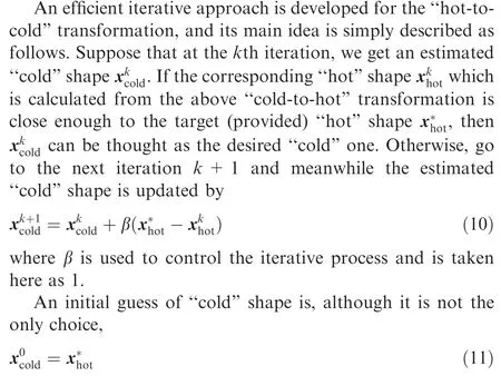
For more clarity, Fig. 3 gives the flow chart of ‘‘hot-tocold” transformation algorithm. Both parameters ε and δ in the two figures are predefined thresholds.
4.2. Results and analysis
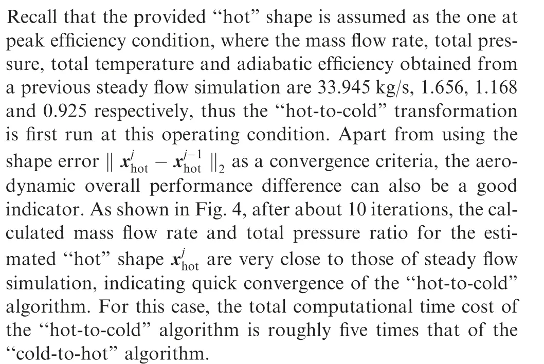
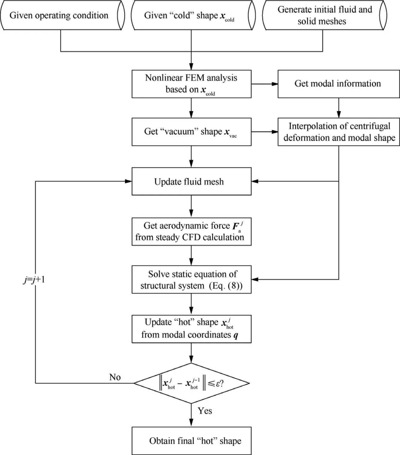
Fig. 2 Flow chart of ‘‘cold-to-hot” transformation algorithm.
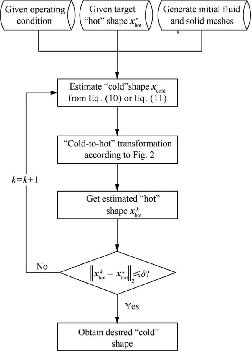
Fig. 3 Flow chart of ‘‘hot-to-cold” transformation algorithm.
In terms of blade deformation analysis, Fig. 5 first intuitively compares the three different shapes at peak efficiency condition,i.e.,‘‘cold”,‘‘vacuum”and‘‘hot”shapes.It is found that both centrifugal and aerodynamic forces lead to the wellknown blade untwist,the former of which is much more significant. This is more quantitatively seen in Fig. 6, where Leading-Edge (LE) and Trailing-Edge (TE) displacements and stagger angel variations along the span are presented.The LE deformation grows exponentially with span, but the TE deformation keeps nearly constant at first and then increases rapidly after about 50%span.The stagger angle variation varies almost linearly from hub to tip. Because the maximum displacement reaches above 6 mm and the maximum stagger angle variation reaches about 2°, it is of great importance to consider this significant shape difference in aerodynamic and aeroelastic analyses.
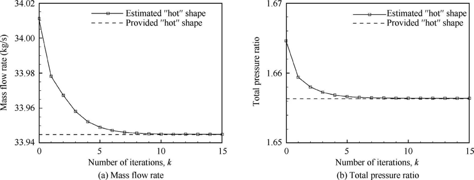
Fig. 4 Calculated overall aerodynamic performance at peak efficiency condition.
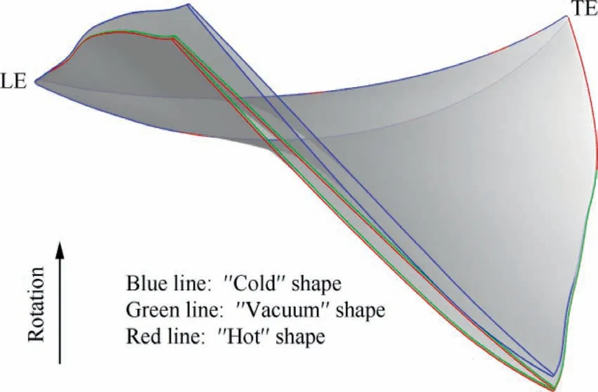
Fig. 5 Comparison of three different blade shapes at peak efficiency condition.
Fig. 7 shows different blade shapes together with the shroud profile near tip in the axial-radial plane.It is found that the ‘‘vacuum” shape overall expands axially relative to the‘‘cold”one and the‘‘hot”shape again slightly expands relative to the ‘‘vacuum” one. Particularly near LE region, the total forward deformation can account for almost 10% of the axial length of the tip section,owing to which blade-casing interference does not occur. In fact, under centrifugal and aerodynamic forces, the blade expands radially near LE region but shrinks at most other region. This indicates that to obtain a uniform ‘‘hot” tip clearance, care should be taken to consider the variation of tip clearance along the axial direction in blade manufacturing process.Fig.8 also shows tip sections of different blade shapes in the axial-circumferential plane. It is seen from this figure and calculated modal coordinates (not shown here) that the first-order bending is the most principle deformation mode.
In terms of aerodynamic analysis, both fixed and variable‘‘hot” shapes are used. For the former one, steady computations are done based on the provided‘‘hot”shape under varying operating conditions, while for the latter one, ‘‘cold-tohot” static aeroelastic computations are done based on the‘‘cold” shape obtained above. As shown in Fig. 9, the predicted design speed characteristics of the variable ‘‘hot” shape agree slightly better with the experimental data than those of the fixed ‘‘hot” shape.
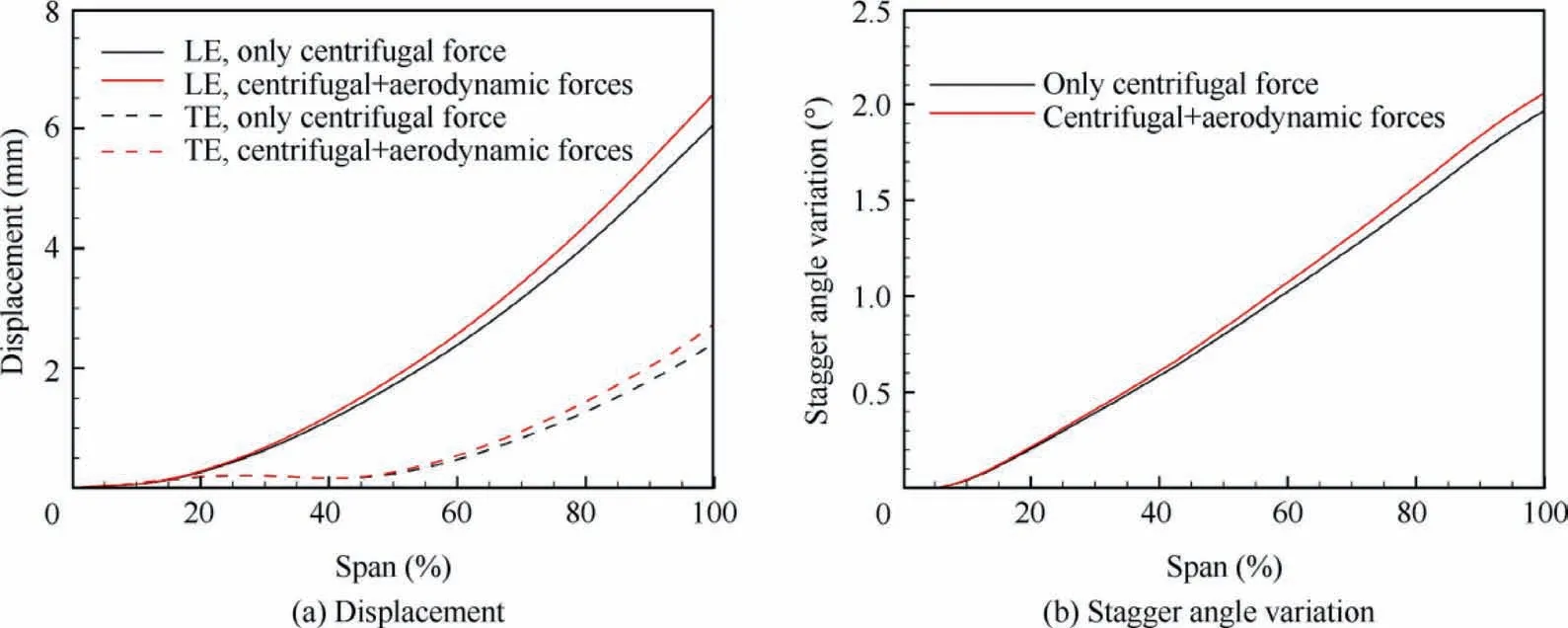
Fig. 6 Blade deformation along span under different forces at peak efficiency condition.
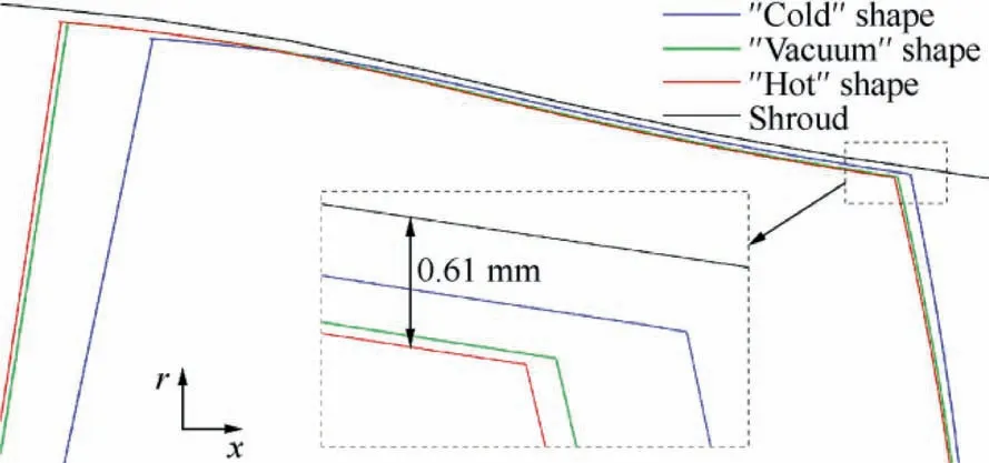
Fig. 7 Different blade shapes and shroud profile near tip in axial-radial plane.
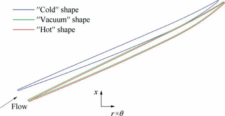
Fig. 8 Tip sections of different blade shapes in axial-circumferential plane.
To further compare the details of flow field, a near peak efficiency condition and a near stall condition, as shown in Fig. 9, are selected to be studied. The calculated spanwise distributions of total pressure ratio, total temperature ratio and flow exit angle at these two typical conditions from fixed and variable ‘‘hot” shapes are given in Figs. 10 and 11. Also presented are the experimental data. For the near peak efficiency condition, good agreements are found between predicted and measured results. The results of fixed and variable ‘‘hot”shapes agree very well with each other,which is to be expected since the provided‘‘hot”shape is defined at the peak efficiency condition. For the near stall condition, differences between results of two ‘‘hot” shapes are more obvious, and they basically increase with span.This again demonstrates the influence of the dynamic variation of ‘‘hot” shape on aerodynamic performance.
Because the used fan rotor with solid blades is rather stiff,differences between ‘‘vacuum” and ‘‘hot” blades are relatively small. From the engineering point of view, it is reasonable to ignore the aerodynamic caused deformation, as has been frequently adopted in practice. However, with extensive use of light and flexible blade structures, the effects of the aerodynamic force would become more important.
5. Flutter prediction and analysis
Based on the former static aeroelastic analysis, this section focuses on flutter prediction of the same fan rotor using both energy method and time-domain method. Before that, it is worth mentioning that only the blade vibration with 0 nodal diameter is studied in this work, i.e., the blades of this rotor are assumed structurally uncoupled. For more sophisticated aeroelastic studies considering blade/disk coupling(flutter with a certain number of nodal diameters and different blade mode shapes), one may refer to.29,30
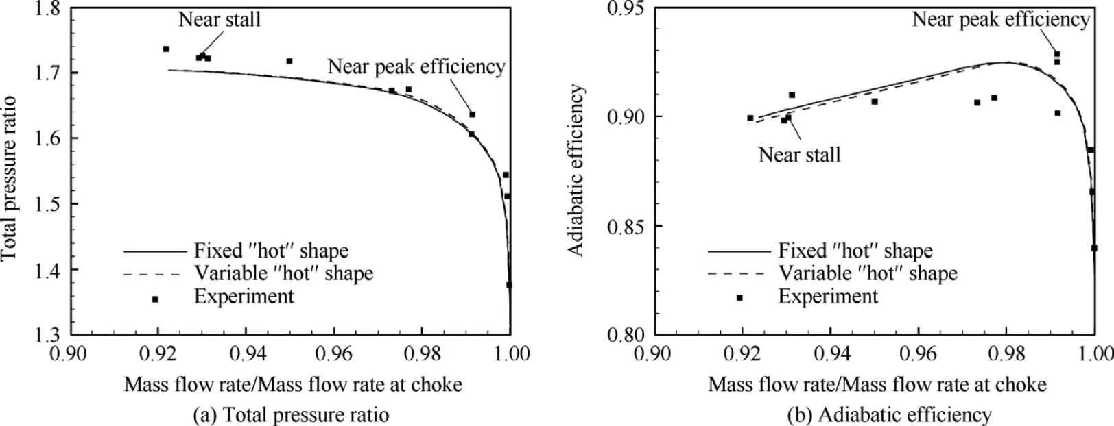
Fig. 9 Fan rotor design speed characteristics.
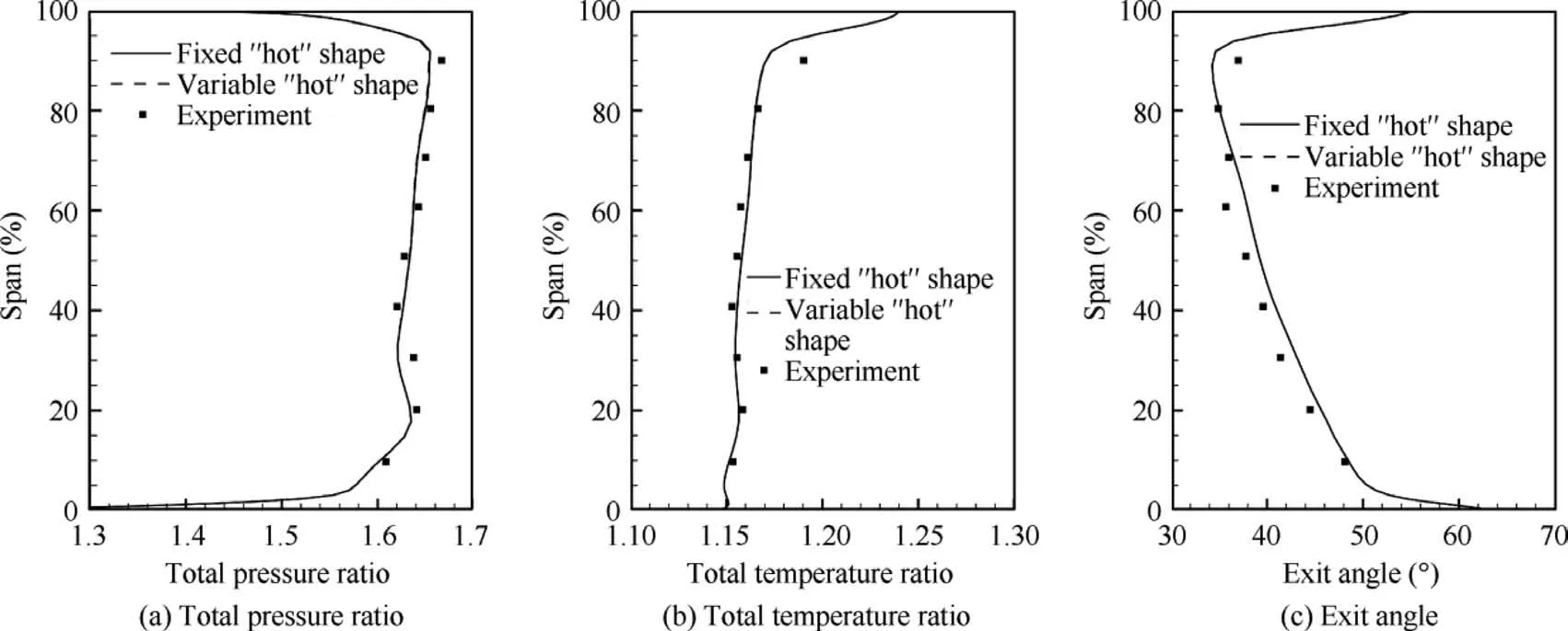
Fig. 10 Spanwise distributions of aerodynamic performance at near peak efficiency condition.
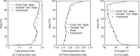
Fig. 11 Spanwise distributions of aerodynamic performance at near stall condition.
5.1. Flutter prediction by the energy method
The specific algorithm of the used energy method is shown in Fig. 12, where the blade is forced to vibrate sinusoidally in some natural modal. In this case, only the dominant first-order bending modal is considered since it plays a dominant role in static aeroelastic deformation and vibration response (shown in the next section). The modal amplitude q is determined to make the maximum displacement at tip to be 1 mm as suggested by Sanders et al.18Following Kersken et al.,31the aerodynamic damping coefficient is defined as

where Wcycleis the total aerodynamic work per cycle of vibration, ω is the natural angular frequency and M is the generalized mass.
For unsteady CFD calculation, each vibration cycle is divided into 180 physical time steps and the number of pseudo time steps is chosen to make the residual fallen by one order or reach a maximum value of 100. At each operating condition,less than 10 cycles are required to gain a converged and stable aerodynamic damping.
As demonstrated above, both fixed and variable ‘‘hot”shapes are used to predict flutter for different operating conditions, and the calculated variations of aerodynamic damping coefficient with mass flow rate are shown in Fig. 13.A similar variation trend is found in the figure, that is, the aerodynamic damping coefficient has two peak values near the peak efficiency point but decreases with the operating condition close to stall margin or choke margin. Since there is no geometric variation between two‘‘hot”shapes at the peak efficiency condition,the resulted damping values are the same.As the operating condition approaches stall, the damping value of the fixed‘‘hot”shape is obviously higher than that of the variable‘‘hot” shape, indicating a negative influence of the dynamic variation of‘‘hot”shape on the evaluated aeroelastic stability.On the contrary,as the operating condition approaches choke,the influence is much smaller.
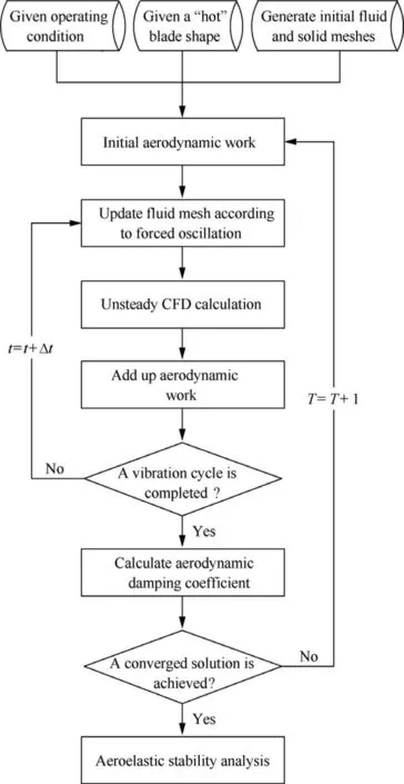
Fig. 12 Flow chart of used energy method.
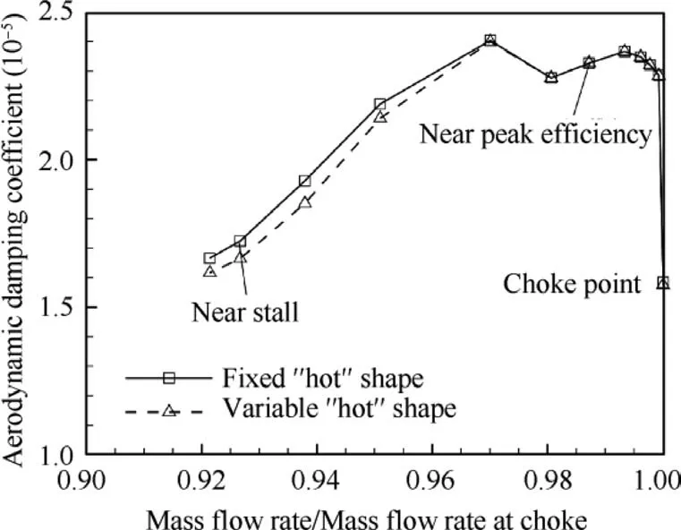
Fig. 13 Calculated variations of aerodynamic damping coefficient with mass flow rate.
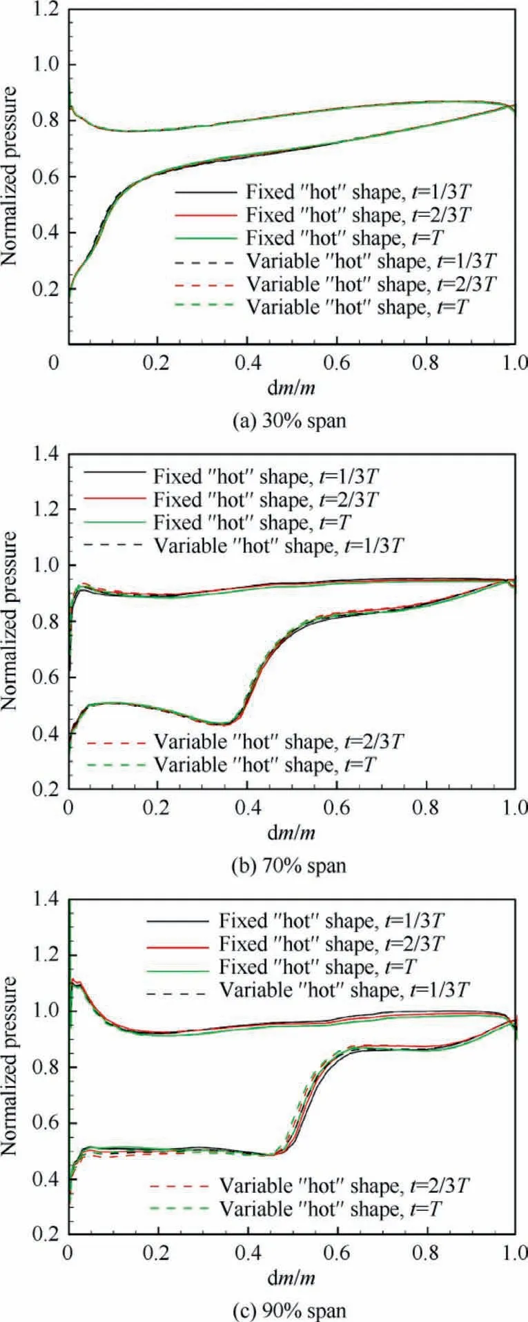
Fig. 14 Instantaneous pressure distributions at different spanwise locations for near stall condition.
To show how the dynamic variation of‘‘hot” shape affects aeroelastic stability, the near stall condition (about 93% maximum mass flow rate) described in Section 4 is chosen to be investigated. Fig. 14 presents instantaneous pressure distributions at three time instants in a vibration cycle (t=1/3T,t=2/3T, t=T) at three typical spanwise locations (30%,70%, 90% span) for the near stall condition. The symbol m represents the curvilinear arc length along the local blade section.It is found that differences between unsteady pressures of fixed and variable ‘‘hot” shapes mainly appear in the suction surface and are more significant at higher span. Particularly at 90% span, the dynamic variation of ‘‘hot” shape leads to an obvious overall movement of the oscillating passage shock.Since it is well known that the presence of shock plays an essential role in affecting the aeroelastic stability, this shock movement is probably associated with the change of aeroelastic stability.
In order to show the relationship between aeroelastic behavior and shock more intuitively, for the same near stall condition, Fig. 15 presents contours of aerodynamic work per cycle of vibration (flood) and instantaneous pressure (isoline) on both suction and pressure surfaces obtained from the variable ‘‘hot” shape. Note that the computational cell area is included in the definition of the local work, which is
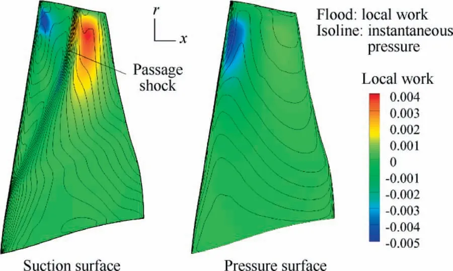
Fig. 15 Contours of aerodynamic work per cycle of vibration(flood) and instantaneous pressure (isoline) on blade surfaces.

As shown in Fig. 15, the major positive-work (unstable)area appears behind 50% chord location of the upper-span sections on the suction surface, which just corresponds to the region behind the passage shock. There are also two concentrated negative-work (stable) areas respectively on the suction and pressure surfaces, both of which are located near leading edge of the upper-span sections. Besides, all the other areas have very small values of aerodynamic work indicating less effect on the aeroelastic stability.
5.2. Flutter prediction by the time-domain method
Based on the two-way fluid–structure coupling, Fig. 16 shows the algorithm of the used time-domain method for the situation where only its ‘‘hot” shape is available. For each operating condition, a 10% disturbance of static aeroelastic deformation (i.e., modal displacements) is artificially imposed to the variable ‘‘hot” shape, on one hand, acting as an excitation source of unsteady flow field,on the other hand,by monitoring which over time, the aeroelastic stability is predicted.For unsteady CFD calculation, the used physical-time-step size and the number of pseudo time steps are set the same as above.
Fig. 17 gives the calculated time responses of modal displacements for the aforementioned near peak efficiency condition and near stall condition, where all modals show convergence trend and the first-order bending modal plays a dominant role. By performing a Fast Fourier Transformation(FFT)of the time-varying response at tip section for any operating condition, it is found that all the peak frequencies in the FFT spectrum correspond to the natural frequencies of the rotor blade, indicating that there is no modal coupling or frequency merging.
Because of the potential of single-degree-of-freedom flutter for this case and the dominance of the first-order bending modal, its time responses for the above two operating conditions are shown in Fig. 18. In order to extract a quantitative parameter that represents the aeroelastic stability from the time response curve, an exponential function a-be-ζωtis introduced to fit all the peak values by using the least square method, where a stands for the static modal displacement obtained previously, b=0.1a for the initial disturbance, ω for the first-order natural frequency and ζ for the unknown decay factor. The effectiveness of this fitting function can be verified as shown in the figure,where the fitted value of ζ is also presented. A positive ζ means that the rotor blade is free of flutter and the bigger this value, the better the aeroelastic stability is, and vice versa.
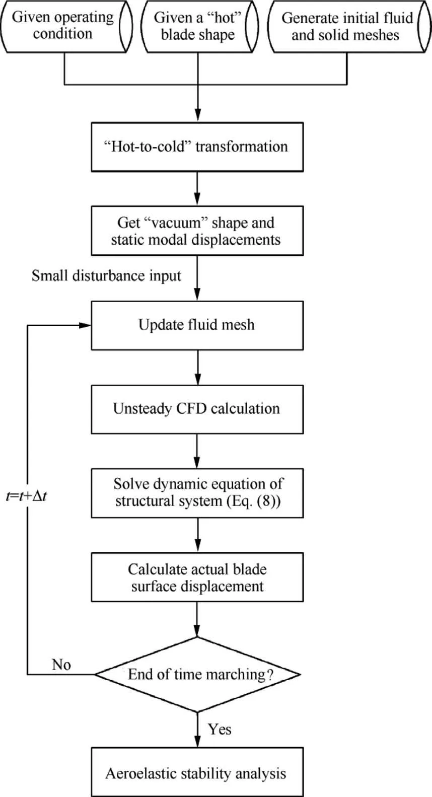
Fig. 16 Flow chart of used time domain method.
By considering more operating conditions, the calculated variation of decay factor with mass flow rate is shown in Fig. 19. The variation trend is found to be in excellent agreement with that shown in Fig. 13, indicating that the energy method and time-domain method which have different extents of fluid–structure coupling predict the same flutter characteristics of Rotor 67. This is to be expected for the two reasons.First, this solid fan rotor blade is relatively stiff and the firstorder vibration modal dominates.Second,the nonlinear effect of aeroelastic behavior in this case is weak.
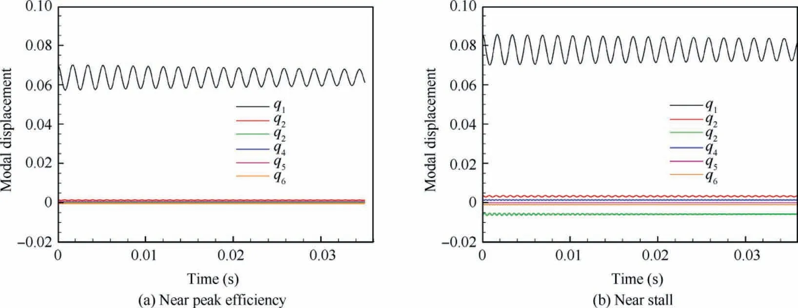
Fig. 17 Calculated time responses of modal displacements.
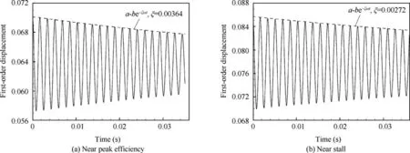
Fig. 18 Calculated time responses of the first-order modal displacement and fitting curves.
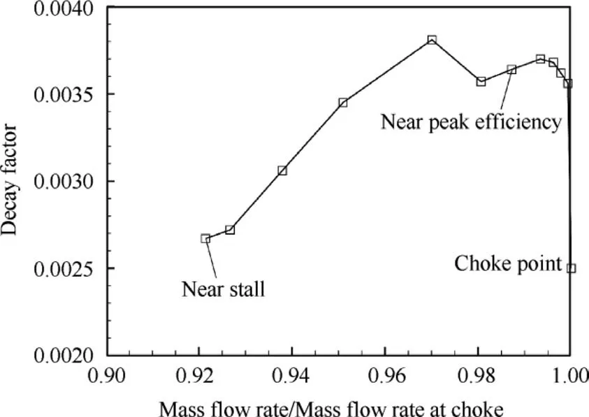
Fig.19 Calculated variation of decay factor with mass flow rate.
Finally,mechanism of decrease of aeroelastic stability when approaching stall and choke margin as shown in Figs. 13 and 19 is briefly discussed. It is known that at the near stall condition, due to the higher outlet pressure, the incidence angle increases leading to flow separation on the suction surface which is firmly related to blade flutter. With continuous increase of outlet pressure, first is the small-scale flow separation region, then the large-scale region and finally the stall appears along with the significant deterioration of aerodynamic performance before blade flutter happens.While at near choke condition,there is no flow separation since the incidence angle has a very small value (either positive or negative) and thus the aerodynamic loading is relatively small. However, it is noticed that when the outlet pressure is decreased to some extent, the passage shock on the suction surface moves downwards and turns to two trailing edge shocks,one traveling to a near-trailing-edge location on the pressure surface of the adjacent blade and the other one propagating further downstream.The authors argue that it is such change of shock structure that causes the rapid decrease of aeroelastic stability when near choke margin.
6. Conclusions
In this paper,computational aeroelastic studies for a transonic fan rotor with only its ‘‘hot” blade shape available are presented. First, ‘‘cold-to-hot” and ‘‘hot-to-cold” shape transformation algorithms are developed for static aeroelastic prediction and analysis. Geometry differences among ‘‘cold”,‘‘vacuum” and ‘‘hot” shapes and aerodynamic characteristic differences between fixed and variable ‘‘hot” shapes are discussed. The necessity of considering the dynamic variation of‘‘hot” shape for more accurate evaluation of the aerodynamic performance is demonstrated.Then we present an algorithm of the energy method for flutter prediction and analysis,and both fixed and variable ‘‘hot” shapes are used. It is found that the dynamic variation of ‘‘hot” shape has a negative effect on the evaluated aeroelastic stability, and this effect might be associated with movement of the oscillating passage shock.Further, a time-domain method is also used to predict blade flutter for the same situation where only a ‘‘hot” blade shape is known, from which the calculated variation of decay factor with mass flow rate has the same trend as the variation of aerodynamic damping obtained from the energy method.
Currently,due to the lack of information of flexible blades,a relatively stiff fan rotor was chosen to be studied,which is a major limitation of this work. It should be stressed that for modern rotor blades that often have larger aspect ratio,lighter weight and more flexible structure,the aerodynamic and aeroelastic effects of the dynamic variation of‘‘hot”shape would be more significant. More practical and sophisticated aeroelastic studies are being conducted.
Declaration of Competing Interest
The authors declare that they have no known competing financial interests or personal relationships that could have appeared to influence the work reported in this paper.
Acknowledgements
This study was supported by National Natural Science Foundation of China (No. 11872212), China Postdoctoral Science Foundation Grant (No. 2019M650112), Natural Science Foundation of Jiangsu Province, China (No. BK20190386)and a project funded by the Priority Academic Program Development of Jiangsu Higher Education Institutions, China.
 CHINESE JOURNAL OF AERONAUTICS2021年7期
- CHINESE JOURNAL OF AERONAUTICS的其它文章
- Integrated batteries layout and structural topology optimization for a solar-powered drone
- Polynomial networks based adaptive attitude tracking control for NSVs with input constraints and stochastic noises
- Morphing wing flaps for large civil aircraft:Evolution of a smart technology across the Clean Sky program
- Review on bio-inspired flight systems and bionic aerodynamics
- SARISTU:Adaptive Trailing Edge Device(ATED)design process review
- Continuous morphing trailing-edge wing concept based on multi-stable nanomaterial
