Reduction of vibration by periodically stitched sandwich panel
Nn LI, Mrouk BEN TAHAR, Ling MENG, Fusheng SUI,d,*
a Key Laboratory of Noise and Vibration Research, Institute of Acoustics, Chinese Academy of Sciences, Beijing 100190, China
b Sorbonne Universite´s, Universite´ de Technologie de Compie`gne, CNRS, UMR 7337 Roberval, Centre de Recherche Royallieu,CS 60319, Compie`gne Cedex 60203, France
c State IJR Center of Aerospace Design and Additive Manufacturing, Northwestern Polytechnical University, Xi’an 710072, China
d School of Physical Sciences, University of Chinese Academy of Sciences, Beijing 100049, China
KEYWORDS Composite structure;Parametric study;Periodic structures;Reduction of vibration;Stitched sandwich
Abstract This work reveals that the addition of periodically distributed stitches to sandwich structure enables a significant reduction of vibration in stop-band and this new functionality is systematically investigated. Firstly, a finite element model which is capable of taking into consideration the three layers of the sandwich as well as the stitches is developed.The diagram of dispersion is calculated by applying Floquet-Bloch theorem to the boundaries of unit cell.With properly chosen properties of stitches,a stop-band for flexural wave is observed.This stop-band is further confirmed by the forced response of a large stitched sandwich panel under point excitation.The level of vibration in the stop-band is significantly reduced.The influence of the stitch rigidity and density on upper and lower limits of stop-band is also examined,which confirms that stitched sandwich can be tuned to mitigate vibration in a certain frequency band with appropriate stitch properties. These investigations have demonstrated the potential application of stitched sandwich in the area of vibration reduction.
1. Introduction
Sandwich structures are widely used in various industrial fields owing to their high flexural stiffness to weight ratio and versatility enabled by various choices of skin and core materials(thermal insulation,1,2sound insulation,3impact absorption4,5and fire resistance6,7among others). However, the mechanical performance of classic sandwich structure in the transverse direction is less satisfactory due to the relatively low rigidity of the core material and poor connection between different layers. Core damage and debonding at the core/skin interface of sandwich panels under impact have been widely recognized and investigated.8–12The concept of stitching, successfully applied to laminates,13has been transferred to sandwich structures to improve the core/skin connection as well as stiffness and strength. The main mythology of stitched sandwich consists in reinforcing the transverse direction by through-thethickness stitches.A stitched sandwich panel made of polystyrene core and carbon fiber/epoxy facesheets is shown in Fig. 1.
Generally speaking, the fabrication of stitched sandwich panel composed of composite facesheets and foam core can be divided into two main steps: stitching of dry preform and moulding.The dry preforms prepared for stitching are stacked in the following order: the foam in the middle of fabrics for top and bottom facesheets.The thread can be inserted into the dry preform through different stitching techniques, among which lock stitch,14modified lock stitch,15–18tufting19,20are commonly used in manufacturing stitched sandwich.The stitching process is usually realized by stitching robot and the stitching parameters such as stitching step and space between stitching rows can be programmed. The holes created by needles in the stitching process connect the upper fabric and lower fabric and provide a path for resin infusion. Thus, the upper fabric,lower fabric and through-the-thickness threads form an interconnected network which can be infused together in the moulding process. For stitched sandwich, Vacuum Assisted Resin Infusion/Vacuum Assisted Resin Transfer Moulding(VARIM/VARTM)is the most commonly used moulding techniques.15,17,20–22When the resin solidifies, through-thethickness threads infiltrated and enveloped by resin will become uniformly distributed solid connections embedded in sandwich structures.
The mechanical effect of stitch addition has been widely discussed,focusing mainly on evaluating the resulting stiffness and strength through mechanical test and damage resistance through impact. Lascoup et al.21,23and Stanley et al.15both launched complete set of mechanical tests on stitched sandwich and provided benchmarks for mechanical evaluation.Lascoup et al.21,23conducted 4 points bending test,flatwise compression test and core shear test on both stitched sandwich with inclined stitches and unstitched sandwich and found that the grain brought by stitches for both modulus and strength in all three cases is significant.Besides panels with angled stitches,Stanley et al.15also tested vertically stitched sandwich panel and concluded that inclined stitches brought more improvement on shear strength than normal stitches. As to damage resistance,the absence of delamination during impact test of stitched sandwich was reported in both works.Beyond these,parametric studies have also been launched and the influence of stitching step,24–26stitching angles,17diameter of the stitching thread27and stitching pattern28–30have been investigated.
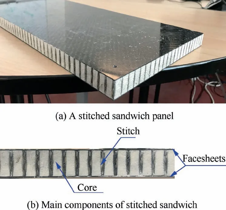
Fig. 1 Periodically stitched sandwich structure.
Besides the improvement in mechanical properties, periodically distributed stitches surprisingly bring another potential functionality, i.e., the mitigation of vibration. If stitching step and distance between two stitching rows are properly controlled during the fabrication process, the stitched sandwich then belongs to periodic structure and is thus capable of attenuating wave propagation in stop-band.
Other than adding through-the-thickness stitches,sandwich structures can be turned into periodic structure in various ways such as sandwich with binary core made of two types of materials,31–33sandwich with periodic hollow tube core34or periodic circular cavity core,35sandwich with periodically inserted resonators in core36and sandwich with periodic attachments on top facesheet.37The vibration reduction effect of these structures is demonstrated and thoroughly discussed in these works,the mechanical aspect of this modification or addition of supplementary parts is nevertheless neglected. The possible cost of weakening the original structure may limit their usage in certain circumstances where mechanical property also counts.For stitched sandwich, vibration reduction effect is only a byproduct of stitching and the improvement in mechanical properties has already been proved.Theoretically,stitched sandwich can be tuned to mitigate vibration in certain frequency band by varying elastic properties and/or density of its constituents including facesheets, core and stitch without adding any additional part. However, this potential functionality of stitched sandwich has not been exploited yet and relation between its properties and stop-band remains unrevealed.
In this paper,we aim at discovering the possibility of using stitched sandwich to reduce vibration. The finite element method developed to model the unit cell of stitched sandwich is briefly reviewed firstly.Then,the dispersion relation is calculated.After that,a stop-band of flexural wave is opened up by varying the stitch properties. The forced response of a large stitched sandwich panel under point excitation is calculated to further confirm the vibration reduction effect in stopband. Finally, a parametric study is launched to examine the influence of stitch rigidity and density on stop-band.
2. Finite element model of unit cell
Stitched sandwich panel is composed of repetitions of unit cell along x and y direction.The unit cell can be defined as a rectangular portion of the stitched sandwich panel with a quarter of stitch at each corner(Fig.2).The length of the unit cell equals stitching step and width equals distance between adjacent stitching rows.
For finite element modeling of unit cell,the stitches and the remaining sandwich panel are modeled individually and then assembled in a global coordinate system. The Finite Element Method (FEM) model and simulation method are described in more details in Ref. 20. They are summarized as below:
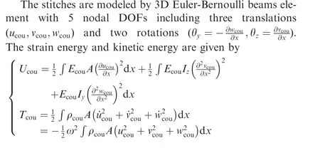
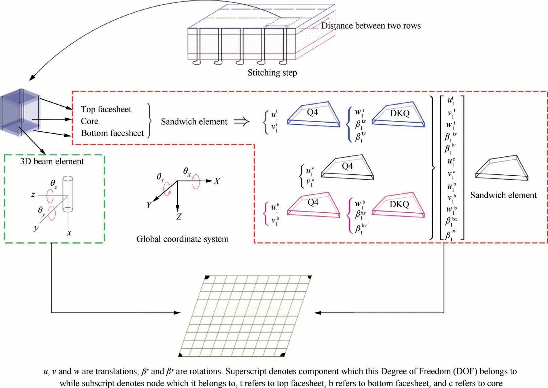
Fig. 2 Finite element model of unit cell.
where Ecouis the elastic modulus of the stitch; A is the cross sectional area; Iy=Izare second moments of area; ρcouis the density of the stitch; ω is angular frequency.
The remaining part is modeled by a sandwich plate element(Fig.2).The two facesheets are thin plates and are thus treated as Kirchhoff plate. The transverse displacement w and two rotations βxand βyare discretized by discrete Kirchhoff element.38In-plane displacements of the middle surface are also taken into consideration and discretized by Q4 element. The core is modeled by thick plate element with quadratic variation of displacement along thickness. Continuity of displacement on the interface of adjacent layers is naturally assured by hypothesis of displacement along z and common DOFs of three layers. Except variables sharing with top and bottom facesheets, the core has introduced only two new variables—i.e.,in-plane displacements ucand vcwhich are also discretized by Q4 element.
3. Calculation of dispersion relation
The governing equation of the unit cell of an elastic system is given by

where K and M are assembled stiffness matrix and mass matrix respectively,which are calculated numerically by finite element modeling in Section 2; f is force vector; q is vector of DOFs and divided into nine parts:

The components of vector q are defined in Fig.3.The division of force vector f is the same as q.
According to Floquet-Bloch theorem and continuity of displacement between adjacent unit cells (detailed in Refs.39–42),the DOFs of the unit cell can be reduced to the base:
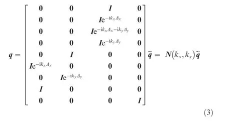
where
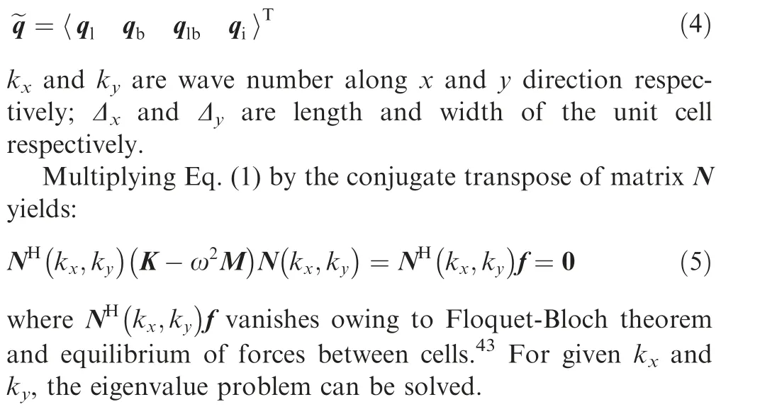
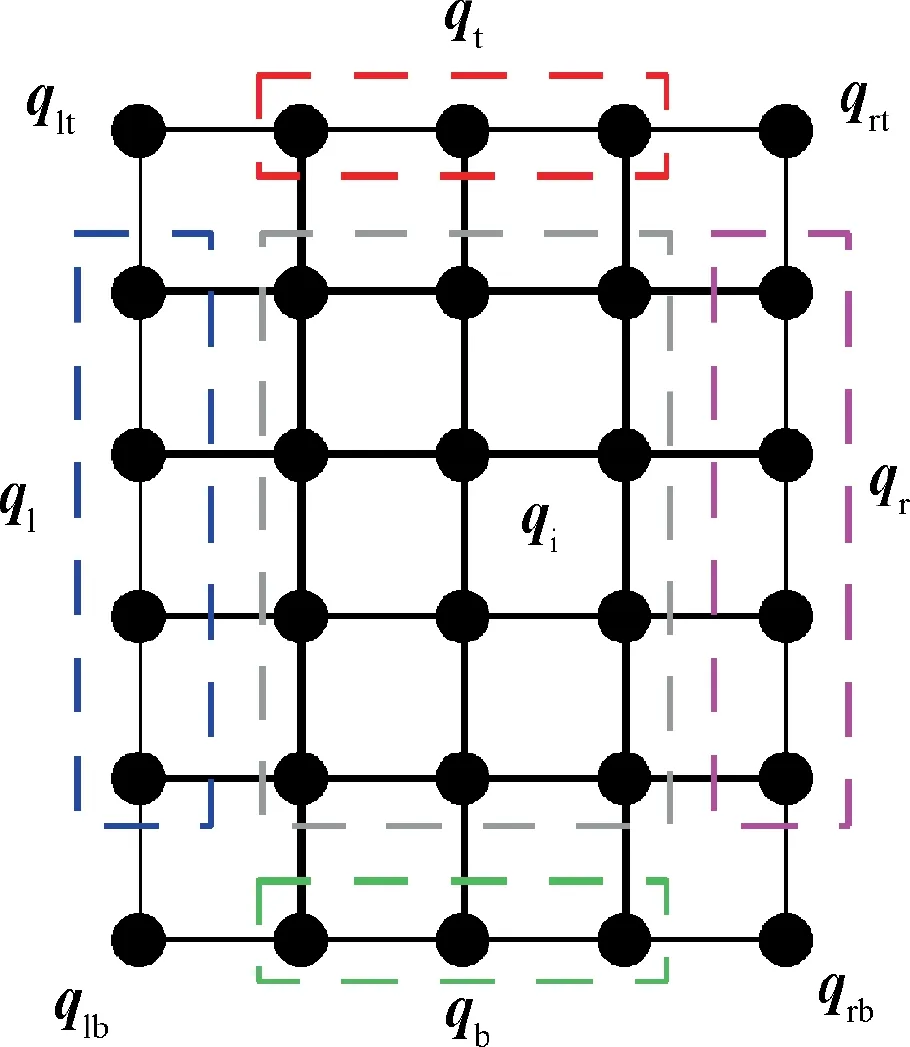
Fig. 3 Division of DOFs of a unit cell.
Although the calculation method mentioned above has already been well established, some interesting characteristics of the solution of Eq. (5) are still worth to discuss before we proceed to applications.For the sake of simplicity,these characteristics are illustrated through two examples of onedimensional propagation—i.e.,kyis always fixed to 0 and only kxvaries.
3.1. Illustration Example 1: Influence of element size in case of fixed cell size
For homogeneous structure (at least homogeneous along the direction of periodicity),the precision of calculation is guaranteed by proper choice of unit cell size.Fake stop-band may be created by improper spatial discretization.39In this case, the unit cell is usually meshed with only one finite element and no attention needs to be paid to element size as it equals the unit cell size.
Unlike homogeneous structure, for periodic structure the unit cell is defined by physical problem and the size of unit cell cannot be changed. This difficulty is usually overcome by meshing the unit cell with more finite elements and element size turns into a key factor which determines the precision of the solution.To facilitate the comparison with analytical solution,the dispersion relation of a homogeneous plate is calculated in this subsection as the influence of element size doesn’t differ in essence.
The diagram of dispersion of an infinite steel panel is calculated with three configurations(elastic modulus E=192 GPa,density ρ=7800 kg/m3, Poisson’s ratio ν=0.3), the unit cell is divided into 1, 4 and 100 elements respectively. The dimension of the unit cell is 1 m×1 m×0.005 m. The comparison with analytical solution is shown in Fig. 4.
The commonly used number of elements per wavelength varies from 6 to 10.44If the most strict requirement (10 elements per wavelength) is considered, wave number k should conform to:
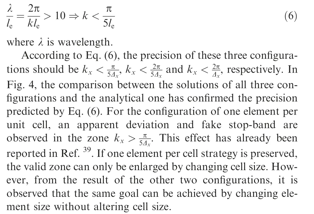
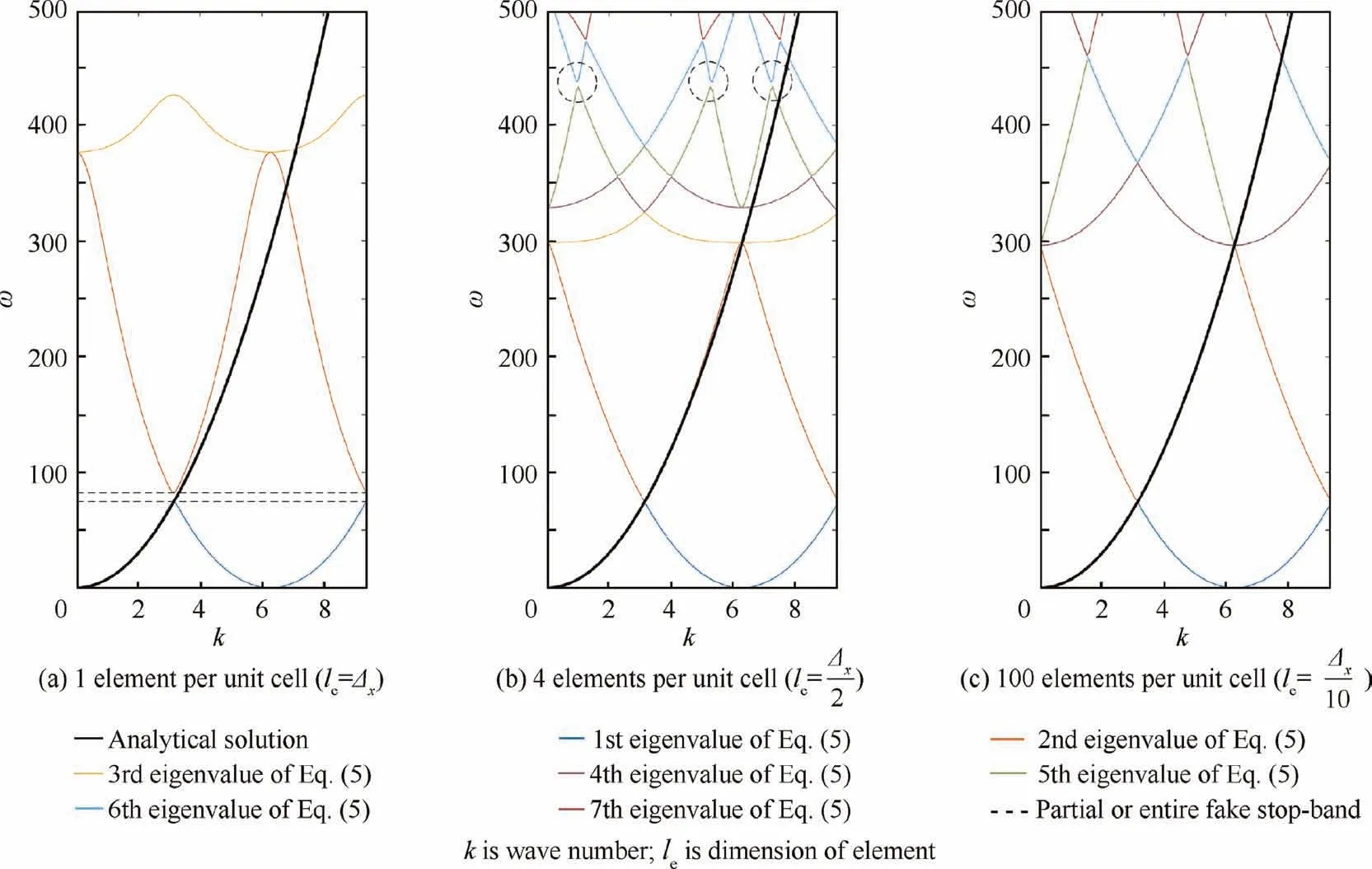
Fig. 4 Diagram of dispersion of three configurations.
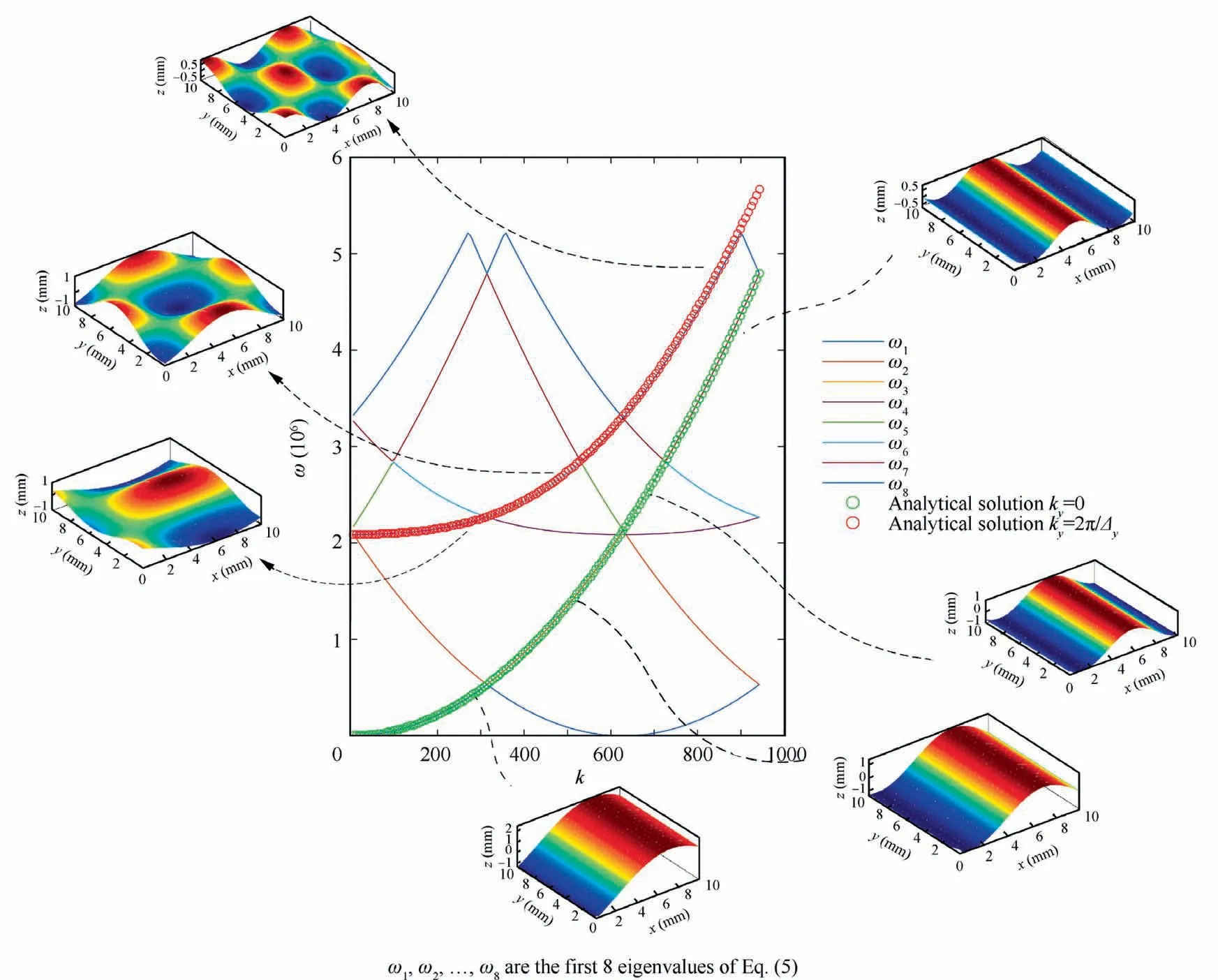
Fig. 5 Comparison of solution of Eq. (5) and analytical solution in case of one dimensional propagation.
3.2. Illustration Example 2: Insight into nature of different curves in diagram of dispersion
We consider an infinite orthotropic plate made of composite materials. The properties of the plate are as follows: elastic modulus in x and y direction E1=49500 MPa,E2=47500 MPa, Poisson’s ratio of plate ν12=0.11, shear modulus G12=3200 MPa, density of plate ρorth=1289.93 kg/m3, thickness of plate h=0.003 m. The dimension of the unit cell is set to 0.01 m×0.01 m and it is discretized by 20×20 Kirchhoff elements.According to Eq.(6),this element size corresponds to the valid zone of kx<.Thus the diagram of dispersion is calculated in the interval [0, 942] which is included in this valid zone.
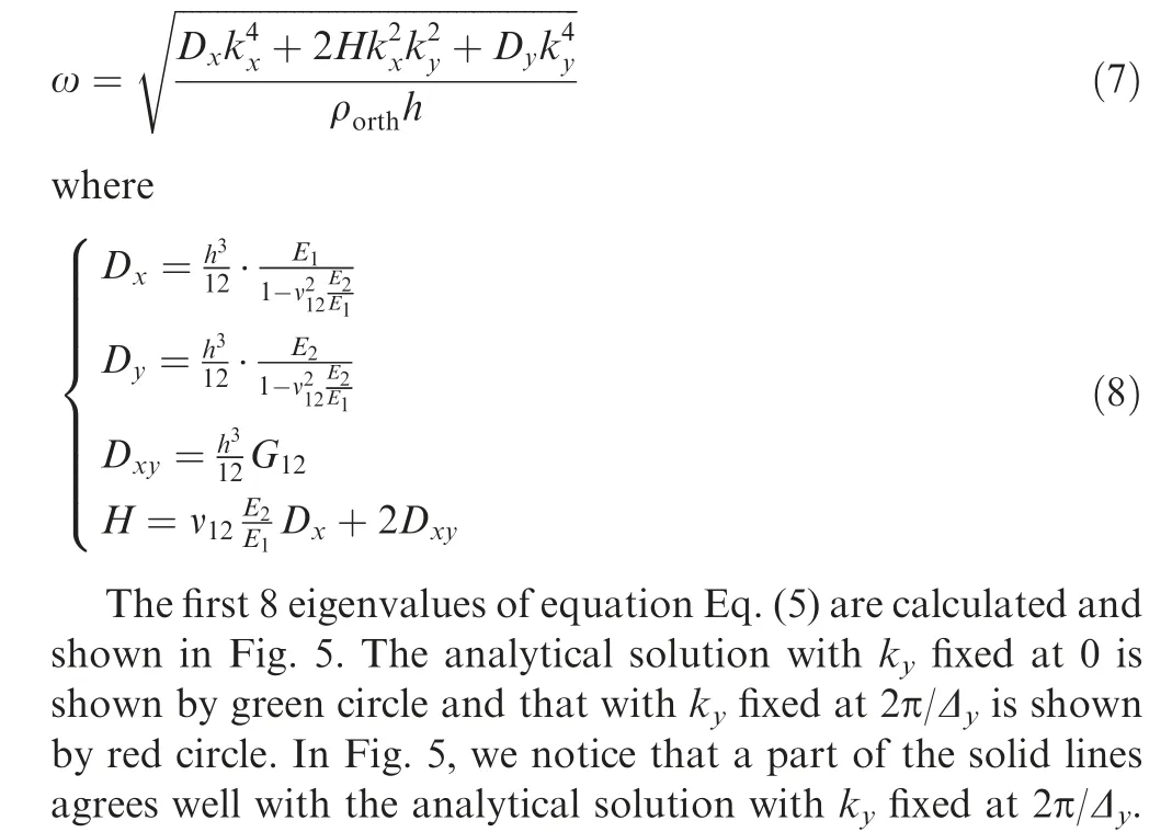
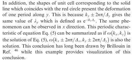
The dispersion relation of an infinite orthotropic plate can also be calculated analytically:45
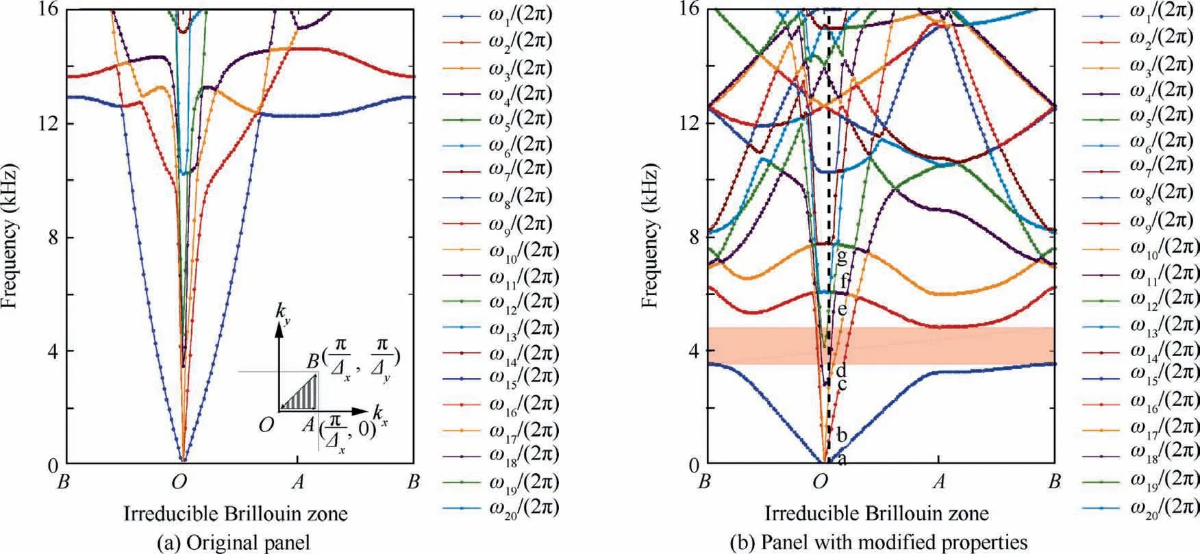
Fig. 6 Dispersion curves of stitched sandwich panel.
3.3. Diagram of dispersion of stitched sandwich
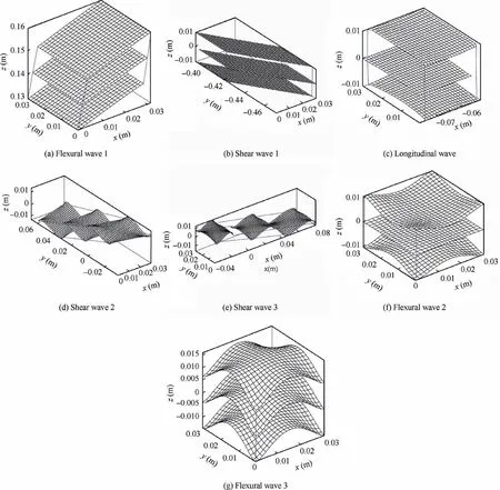
Fig. 7 Deformation of unite cell.
We take the geometric parameters, density and mechanical properties of a stitched sandwich panel reported in Ref.20as follows: thickness of top facesheet h1=1.14 mm, thickness of bottom facesheet h2=1.11 mm, density of top facesheet ρ1=1456.335 kg/m3, density of bottom sheet facesheet ρ2=1388.57 kg/m3, diameter of stitch D=3.93, density of stitch ρcou=1085.05 kg/m3,thickness of core hc=19.85 mm,density of core ρc=35.5 kg/m3, elastic modulus of top facesheet in x and y direction E11=52049.05 MPa,E12=68003.11 MPa, shear modulus of top facesheet G1=5061.96 MPa, elastic modulus of bottom facesheet in x and y direction E21=52064.93 MPa, E22=68041.66 MPa,shear modulus of bottom facesheet G2=5065.84 MPa, shear modulus of core Gc13=13.91 MPa, Gc23=5.38 MPa, elastic modulus of stitch Ecou=2969.78 MPa. The step of stitching and the distance between rows of stitches are both 0.01 m.The diagram of dispersion is calculated by varying kxand kyin Eq. (5) along the border of the irreducible Brillouin zone(lower right corner of Fig. 6(a)). From the dispersion curve shown in Fig. 6(a), we can see that there are no stop-band in the frequency band from 0 to 16000 Hz.
We kept the properties of facesheets and core,and changed stitching step and stitch rigidity and density which can be manipulated by altering the type of stitching thread as well as stitching needle.Fig.6(b)depicts the dispersion curve of a stitched sandwich panel with stitches 1000 times more rigid and 10 times heavier than the original panel(Emod=103Ecou,ρmod=10ρcou).The stitching step and distance between adjacent rows are both changed to 0.03 m. A large stop-band of flexural wave appears around 4000 Hz with these modified properties (red zone).The nature of this stop-band is determined by checking the mode shapes of waves in and near this stop-band. The mode shapes corresponding to the first 7 eigenvalues with wave number kx=,ky=0 (a–g marked in Fig. 6(b)) are depicted in Fig. 7. According to Fig. 7, the propagating waves existing in this band are shear wave(Figs.7(b),7(d)and 7(e))and longitudinal wave(Fig.7(c)).There is no propagating flexural wave in this band.In addition,this band is located between the dispersion curve of Figs.7(a)and 7(f)which are both flexural waves.Consequently,it is a stop-band of flexural wave.
4. Forced response of a stitched sandwich panel under point excitation
As there are no propagating flexural waves in the stop-band,the vibration in the transverse direction of the panel should be considerably reduced. The reduction of vibration can be quantified by calculating the transfer receptance of the panel under point excitation.Since the dispersion relation calculated in Section 3.3 illustrates the behavior of infinite plate, the forced response of infinite stitched sandwich panel would be the most suitable to illustrate this vibration reduction effect.The forced response of infinite panel may be accessed through employing perfectly matched layer,but the zone of exact solution is still restricted to a finite domain. Approximating the infinity by a panel large enough is a more realistic alternative and has been commonly used in related works.
In this section, we consider a stitched sandwich panel containing 400 unit cells,20 unit cells along direction x and 20 unit cells along direction y.Each unit cell has one quarter of stitch at each corner.In order to keep perfect periodicity,the stitches are not all the same across the whole panel. Fig. 8 depicts the detailed configuration: one quarter of stitch is located at each of the four corners,half stitch is located at borders except corners, entire stitches are distributed at inner part of the panel.The force is applied at the point marked in Fig. 8 along the transverse direction.
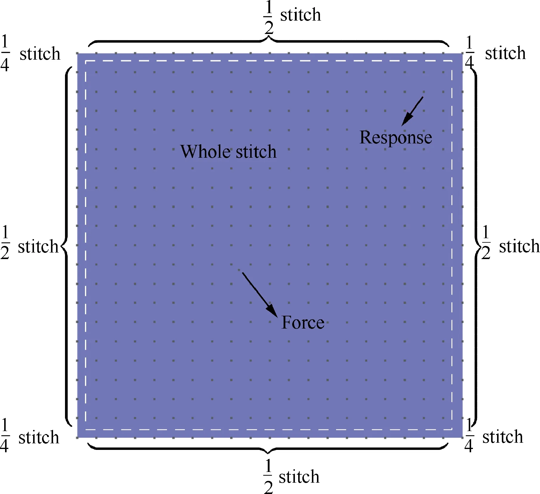
Fig. 8 Configuration of stitched sandwich panel.
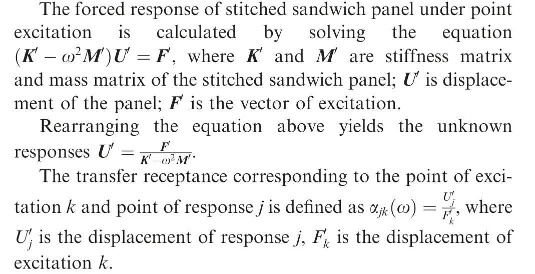
The transfer receptance at the points marked in Fig. 8 is calculated and shown in Fig. 9(b). From the transfer receptance curve, we can see that the vibration level in the stopband is significantly reduced. The deformation of the stitched sandwich panel at three frequencies (marked by a–c in Fig. 9(b)) in and out of the stop-band is depicted in Fig. 10. In the stop-band (Fig. 10(c)), the deformation only occurs in a small zone around the excitation and doesn’t propagate further.This phenomenon is a direct result of characteristics of waves that exist in the stop-band: only evanescent waves and oscillating decaying wave exist and the response is the synthesis of these waves. In our case, propagating waves other than flexural waves do exist in this stop-band but they don’t contribute as much as flexural waves to the response along the transverse direction.While out of the stop-band,the deformation spreads all over the whole panel (Figs. 10(a) and 10(b)). This example demonstrates clearly the potential of stitched sandwich in the aspect of vibration reduction.
5. Parametric study
In this section, the properties of the two facesheets and core are kept unchanged while the influence of the parameters related to stitches on the position and width of stop-band is investigated. The modified properties of stitch (Emod, ρmodand stitching step and distance between two rows are both 0.03 m) used in Section 3.3 serve as references and the rigidity and density of stitch will vary in their vicinities.The upper and lower limits of the stop-band with varying stitch rigidity are depicted in Fig.11.The upper limit rises as the elastic modulus of the stitch increases until elastic modulus reaches 102Ecou,after which the curve flattens into a horizontal line. The curve of lower limit is flat in the whole interval of interest, which indicates the lower limit is insensitive to the variation of rigidity. This trend can be explained by observing the deformation of unit cell at different points marked in Fig. 11. When the stitch is relatively soft (point b in Fig. 11), the second flexural mode (Fig. 12(b)) is a coupled mode in which both the deformation of the plate and deformation of stitch are significant.As the deformation of the stitch is also involved, the upper limit is influenced by the rigidity until the stitch becomes too rigid.At point d,the plate undergoes appreciable deformation while the stitch is hardly deformed (Fig. 12(d)). The influence of stitch rigidity becomes negligible from this point and the curve thus flattens. As to the lower limit, the deformation of the plate dominates from the beginning (Figs. 12(a) and 12(c)). As a result, the eigenvalues in the whole interval of interest are not sensitive to the change of stitch rigidity.
The varying trend of the upper limit and lower limit as a function of stitch density is shown in Fig. 13. The rigidity of stitch and stitching step are kept the same as the reference value in this process. The lower limit declines as the density of the stitch increases while the curve of the upper limit is flat. In order to explain the different behaviors of upper limit and lower limit as the density increases, the deformation of a slice of stitched sandwich panel corresponding to points a and b marked in Fig. 13 is depicted in Fig. 14. This slice is composed of 20 unit cells. The first flexural mode—i.e., the lower limit, is a global mode which involves both the movement of the stitch and the bare sandwich panel.As a result, the lower limit is sensitive to stitch density.As to the upper limit, the displacement of the plate is considerably larger than that of the stitch which almost remains still. Consequently, the upper limit doesn’t change much as the density increases.
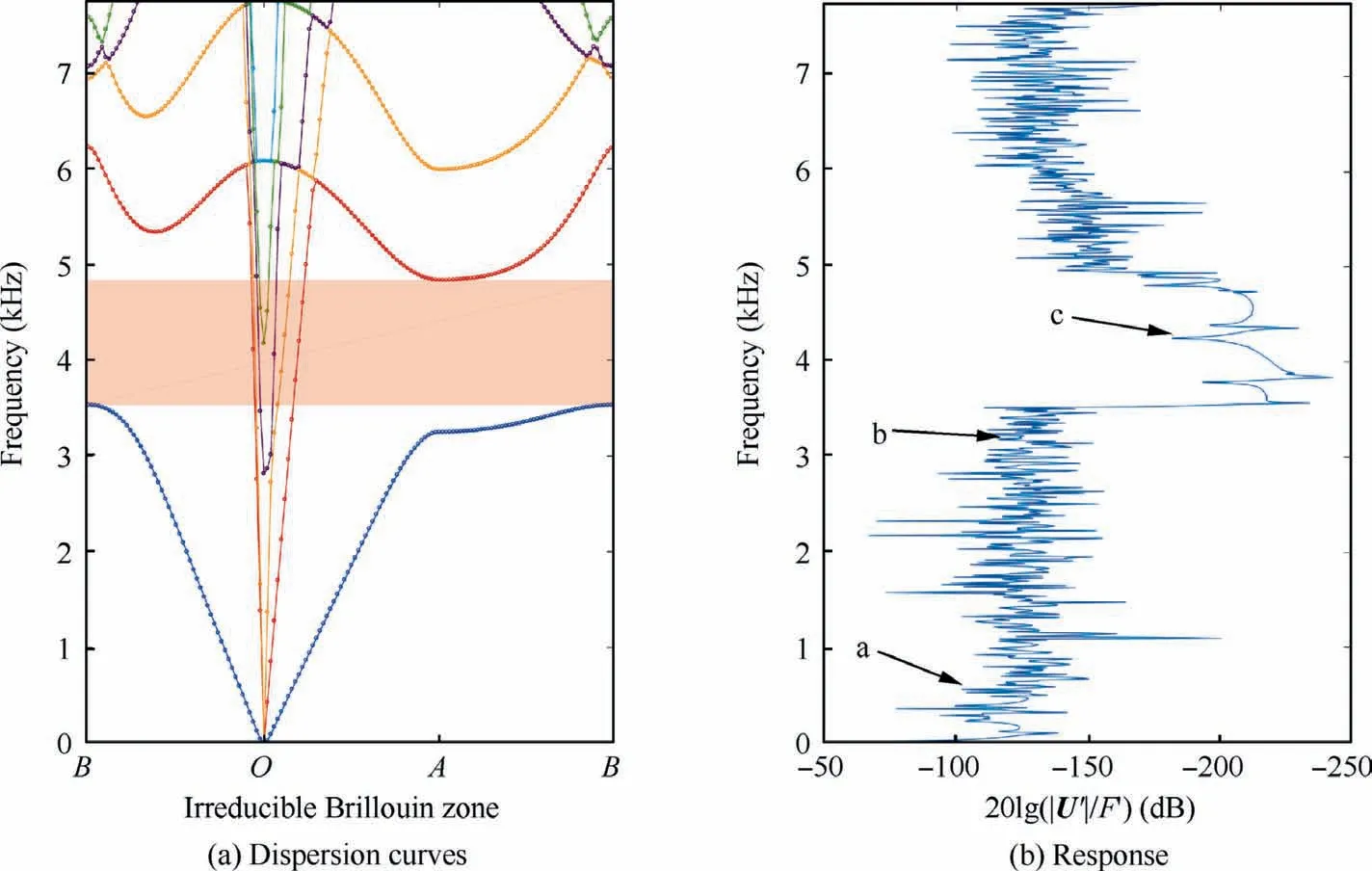
Fig. 9 Response in and out of stop-band.

Fig. 10 Deformation of stitched sandwich panel in and out of stop-band.
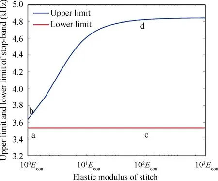
Fig.11 Influence of stitch rigidity on upper limit and lower limit of stop-band (ρmod=10ρcou; stitching step and distance between two adjacent rows are both 0.03 m).
6. Conclusions and future work
Stitched sandwich is in fact a multi-functional structure. The addition of through-the-thickness stitches, on one hand, has reinforced the original structure in the transverse direction,and, on the other hand, enables its application in the area of vibration reduction. In this paper, we have calculated the diagram of dispersion of stitched sandwich and found a stop-band of flexural wave with modified properties of stitches. The forced vibration of a stitched sandwich panel under point excitation is calculated and the vibration level of this panel in the stop-band is considerably reduced.A parametric study reveals that the stop-band can be tuned in a large range by varying stitch rigidity or density.
The conclusions mentioned above set the stage for further research in the future. Experimental investigations including a survey for proper needle diameter and material of stitch thread to achieve the desired rigidity and density and vibration test of stitched sandwich with altered stitch properties, will be launched.Another interesting direction would be optimization of the width and position of stop-band with respect to stitch properties. In addition, particular attention must be paid to the NonDestructive Testing (NDT) of periodic structure as there is no propagating waves in certain frequency band.
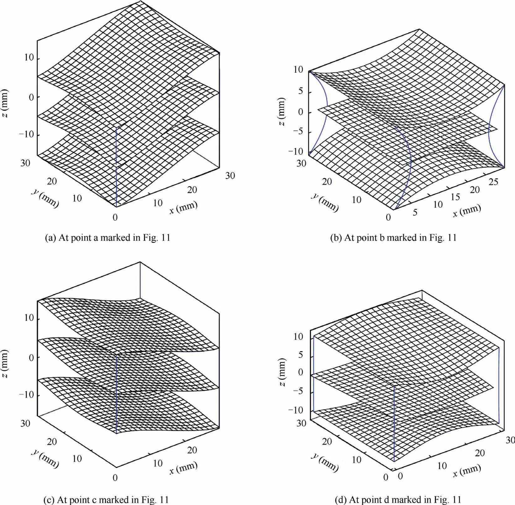
Fig. 12 Deformation of unit cell.
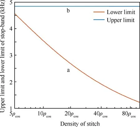
Fig.13 Influence of stitch density on upper limit and lower limit of stop-band(Emod=103Ecou;stitching step and distance between two adjacent rows are both 0.03 m).
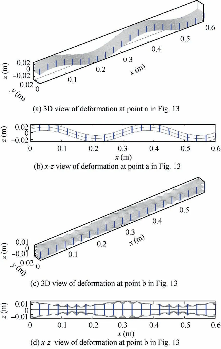
Fig. 14 Deformation of 20 cells (wave number kx=9π/50,ky=0).
Declaration of Competing Interest
The authors declare that they have no known competing financial interests or personal relationships that could have appeared to influence the work reported in this paper.
 CHINESE JOURNAL OF AERONAUTICS2021年7期
- CHINESE JOURNAL OF AERONAUTICS的其它文章
- Integrated batteries layout and structural topology optimization for a solar-powered drone
- Polynomial networks based adaptive attitude tracking control for NSVs with input constraints and stochastic noises
- Morphing wing flaps for large civil aircraft:Evolution of a smart technology across the Clean Sky program
- Review on bio-inspired flight systems and bionic aerodynamics
- SARISTU:Adaptive Trailing Edge Device(ATED)design process review
- Continuous morphing trailing-edge wing concept based on multi-stable nanomaterial
