Determining effects of impact loading on residual strength of fiber-metal laminates with grid-characteristic numerical method
Katerina BEKLEMYSHEVA, Vasily GOLUBEV, Igor PETROV,Alexey VASYUKOV
Moscow Institute of Physics and Technology, Dolgoprudniy, Russia
KEYWORDS Fiber-metal laminate;Grid-characteristic method;Low-velocity impact;Numerical modeling;Residual strength
Abstract The Grid-Characteristic numerical Method(GCM)that is quite common in solving aero and hydrodynamic problems can also be applied for mechanics of solids. It allows to implement complex border and contact conditions, including the non-reflecting border and the destructible contact. Both this conditions are very important for the precise and effective modeling of Low-Velocity Impacts(LVI)on fiber and Fiber-Metal Laminates(FML)and the resulting Barely Visible Impact Damage (BVID)that influences the residual strength of a composite aircraft part.BVID is the type of damage that is not visible by the naked eye and can be hardly detected by a standard ultrasound equipment that is used for regular maintenance.It can appear during any weak impacts like bird strike or hail.Determining its influence on the residual strength of the part is very important to define the priorities of development of ultrasound diagnostics. In this paper, the GCM was applied for a full cycle of loading of an FML aircraft cover part. The FML consisted of a Carbon Fiber Reinforced Polymer (CFRP) and a single titanium layer on the upper surface. The cycle of loading in a single calculation consisted of an LVI caused by a small striker and a comparatively slow compressive in-plane loading. Three-dimensional patterns of velocity and stress distributions over the time of calculation are given. Destruction patterns, obtained via the Hashin failure criterion are given and analyzed.
1. Introduction
The grid-characteristic numerical method was applied for mechanics of solids in various research fields,including seismic survey,1–3ice research,4impact damage,5,6medical ultrasound,7low-velocity impact on fiber and fiber metal laminates.8,9The grid-characteristic numerical method allows to implement complex border and contact conditions, solving the contact discontinuity problem in a stable and mathematically correct way. The non-reflecting border that is used to model an effectively infinite bulk of material in the seismic survey can be applied to model the local damage after the lowvelocity impact without the necessity to model the whole part,decreasing the calculation time. The destructible contact is used to model the delamination – the failure of contact between composite plies that affects the residual compression strength. Both this conditions are very important for the precise and effective modeling of low-velocity impacts on fiber and fiber-metal laminates.
There are different numerical methods that are used for modeling mechanics of solids.9–11All of them have different advantages and limitations, analyzing and comparing the methods is not the main purpose of this paper.Typically methods target either dynamic or static problems, and this makes modeling of certain processes quite complex task, since engineering problems may involve both fast dynamic and static stages. This paper aims to use the single grid characteristic method for such a task.
Fatigue damage evaluation is a very important problem in aircraft development12that requires a rigorous research in various fields of science. Composite materials are very effective and widely used, but their complex structure leads to complex and often unpredictable behavior under dynamic loading.The barely visible impact damage that often appears after a lowvelocity impact influences the residual strength of a composite aircraft part.10,11Barely visible impact damage is the type of damage that is not visible by the naked eye and can be hardly detected by a standard ultrasound equipment that is used for regular maintenance. It can appear during any weak impacts like bird strike,13gravel impact or hail. Determining its influence on the residual strength of the part is very important to define the priorities of development of ultrasound diagnostics.At the same time, experiments on this subject are very expensive–both in terms of composite consumables for the destruction testing and in terms of necessary equipment. A threedimensional pattern of barely visible impact damage is visible at electromagnetic microwaves14or magnetic resonance imaging,15but is not well detectable by the ultrasound that is more accessible.
In this paper,the grid-characteristic numerical method was applied for a full cycle of loading of a fiber metal laminate aircraft cover part. The fiber metal laminate consisted of a Carbon Fiber Reinforced Polymer (CFRP) and a single thin titanium layer on the upper surface.16CFRP of two types were modeled. A single-ply with loading along and across fiber direction and two plies with different respective directions.Each ply was modeled as a homogenous anisotropic material with the destructible contact condition between plies and between the upper ply and the titanium layer. The cycle of loading in a single calculation consisted of a low-velocity impact caused by a small titanium striker and a comparatively slow compressive in-plane loading.Three-dimensional patterns of velocity and stress distributions over the time of calculation are given.The Hashin failure criterion17was used.Destruction patterns are given and analyzed. Several experimental studies on this topic were summarized in,18but reproducing a statement even for a 16-ply composite requires to refine the mesh and to optimize the grid-characteristic numerical method program package.
2. Mathematical model and numerical method
2.1. Mathematical model and failure criterion
The CFRP was modeled as an orthotropic viscoelastic material. The elastic model was used due to comparatively fast –in fact, acoustic – time scale of the loading. The Maxwell viscosity model was used, and its implementation into the gridcharacteristic numerical method is thoroughly described in.19
2.2. Grid-characteristic numerical method
The grid-characteristic numerical method is used for hyperbolic systems of equations, and can be applied for threedimensional destructible anisotropic viscoelastic materials with plasticity by introducing the splitting by physical processes and spatial dimensions. The full mathematical statement and the calculation algorithm are given in,7,19and the general idea is as follows.
The calculation in this research was performed on regular cubic grids, because the target area has a simple form. The grid-characteristic numerical method can be applied for irregular tetrahedral grids,but it increases the calculation time.The equations system for an elastic material is:
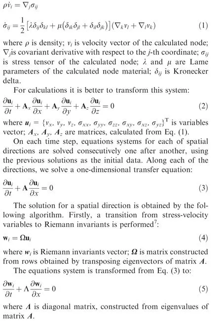
Thus,the hyperbolic equations system breaks up into a set of independent transport equations.Each of this equations has an exact solution that can be found by dropping a characteristic line on the previous time step according to the corresponding spatial direction and the eigenvalue. The approximation order of the method is determined by the approximation order of interpolation that is used to restore the exact solution from values in the grid nodes.In this research,first and second order interpolations areused.AfterallthetransportequationsforRiemanninvariants are solved,the original set of variables can also be restored.After that,allthe nodes of the calculation grid are checked for fulfilling thedestructioncriterion.Intheendonthetimestep,correctorfor plasticityindestructednodesisapplied.Thisalgorithmisapplied for all the grid nodes one after another.
There are limitations on the time step that follow both from the numerical method and from the spatial discretization as well. The standard Courant time step for the material with the largest elastic wave speed is used in this research–it means that a characteristic line falling from a node falls in a nearby grid element. More importantly, it means that only border nodes will have characteristic lines that fall out of the calculation grid and require border conditions.
2.3. Hashin failure criterion
The failure criterion used in this research is the Hashin failure criterion. First two formulas determine the fiber damage:
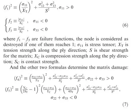
where f4–f5are failure functions;YTis tension strength across the ply direction;STis shear strength for fibers,YCis compression strength across the ply direction.
As it was shown in Ref.8,different failure criteria give different damage patterns evenwith the same strength parameters,but qualitativeresultstendtostaythesame.Thebestcorrespondence with the experimental data was obtained with the Hashin criterion.Also,it allows to distinguish different damage modes without requiring to introduce additional material parameters.
3. Numerical results
3.1. Problem statement
The aim of this research was to determine the influence of barely visible impact damage caused by a low-velocity impact on the residual strength of fiber and fiber-metal laminates.Several three-dimensional model problem statements were studied, the general view of the calculation area is given on the Fig. 1. The striker and the upper layer are titanium, middle and bottom layers are unidirectional CFRP plies with alignments that depend on a statement.
A composite plate 20 cm×20 cm was modeled. It consisted, depending on a statement, of two thick 5 mm CFRP unidirectional plies with different stacking sequence or of the same two CFRP plies with a 2 mm titanium layer on the upper surface. Stacking sequence [0°/0°] is further referenced as ZZ(in both plies the fiber direction is along the Z axis), stacking sequence [90°/90°] – as XX, stacking sequences [0°/90°] and[90°/0°] – as ZX and XZ respectively, the first letter denotes the alignment of the upper layer.
The low-velocity impact was modeled with a 5 mm×5 mm×5 mm cubic titanium striker. The shape of the striker was taken as cubical due to calculation grid limitations.Regular cubic grid allowed to accelerate calculations and effectively model comparatively wide and thin layers with large contact surfaces.At the same time,modeling of more complex striker shapes raises the question of mesh convergence,because in case of convex striker shape the size of contacting area depends both on the grid element size and on the contact threshold.The quasi-static,slow loading was modeled as external force border conditions on the bordering YZ planes,so the pressure was directed to the center of the plane along the Xaxis. The pressure changed linearly from zero to a maximum value in 12 mcs, which was enough for elastic waves from the impact to propagate and deteriorate,forming the resulting barely visible impact damage. The calculation continued until the damage pattern was stable for ten time steps and stresses across the calculation area were not high enough to cause any further damage. All the other surfaces are free borders –external force border conditions with zero value. This set of border conditions models the specimen supported from sides along the X axis.
The CFRP was modeled as a homogenous orthotropic material with the Hashin failure criterion. The material parameters are as follows.20Elastic parameters are: c11=23.30 GPa, c12=c13=c23=6.96 GPa, c22=c33=12.00 GPa,c44=1.67 GPa,c55=c66=5.01 GPa;density ρ=1.6 g/cm3, tension strength along the ply direction XT=26.30 MPa, compression strength along the ply direction XC=15.30 MPa, tension strength across the ply direction YT=2.13 MPa, compression strength across the ply direction YC=0.86 MPa, shear strength for fibers ST=15.30 MPa,shearstrengthforthematrix S=1.12 MPa. Contact strength SC=1.12 MPa. The damaged area was modeled as a zone with a Prandtl-Reiss plasticity material model with a zero plasticity limit.
The titanium was modeled as an indestructible homogenous isotropic material with the following parameters: Lame coefficients λ=120 GPa, μ=4.7 GPa; density ρ=4.5 g/cm3.
The contact between the striker and the plate is the sliding contact condition without friction, other contacts are destructible with the same contact strength SC. We estimated the strength of contact between CFRP and titanium layer as the upper bound – the strength of matrix material that serves as a glue both between CFRP plies and between CFRP and titanium.
3.2. Dynamic patterns of stress and velocity
To illustrate the loading process, let us demonstrate velocity patterns for several time steps during the first stage of loading.On Fig. 2 the velocity modulus distribution is presented for a two-ply CFRP,armed with a titanium layer,stacking sequence is ZZ.
Stress and velocity patterns are not very informative in the paper format, thus only the damage patterns will be given for the rest of the calculation.
3.3. In-plane loading of CFRP
In this paragraph, destruction patterns for a two-ply CFRP after a quasi-static in-plane loading with different amplitude are given. No low-velocity impacts or titanium layers are present.
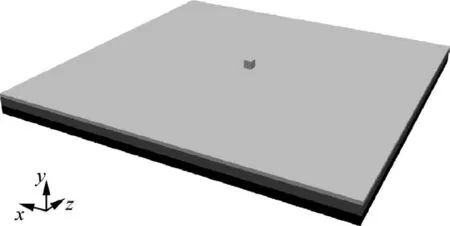
Fig. 1 General view of calculation area.
On the Fig.3 failure areas for a two-ply CFRP after an inplane loading of 7.5 MPa are given, and the Fig. 4 shows a loading of 10 MPa. Delamination patterns are not included,because it’s either no destruction for XX and ZZ stacking sequences, or full destruction for XZ. These figures show that if a fiber direction is the same in both plies,the damaged area is smaller or absent.
For the XZ stacking sequence, we can see a characteristic damage pattern.The ply with Z fiber alignment shows a damage pattern (Fig. 3(c)) similar to the damage pattern of ZZ sequence under a stronger loading (Fig. 4(a)). Unlike typical damage patterns in classic isotropic homogenous construction materials, these cracks are not directed at an angle of 45°.
According to Hashin failure criterion, the fibers are left intact,and the damaged area consists of matrix cracks.A small amount of these cracks leads to the appearance of barely visible damage, but a large amount, like in the right column of both Figs. 3 and 4, leads to the loss of material integrity.The calculation models a respectively short amount of time,so the deformations are not clearly visible,but further loading would lead to a complete destruction of the specimen.
On the Fig.5 failure areas for a two-ply CFRP after a lowvelocity impact of a 5 mm×5 mm×5 mm titanium striker with a velocity of 0.6 mm/s and an in-plane loading of 7.5 MPa are given, and on the Fig. 6 – a loading of 10 MPa.
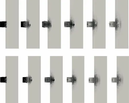
Fig. 2 Velocity modulus during the initial low-velocity impact for a two-ply CFRP, armed with a titanium layer, stacking sequence is ZZ.From left to right–consecutive time steps.On top–a cut in YZ plane,on bottom–a cut in XY plane.Velocity range is from 0(white)to 0.6 mm/s.
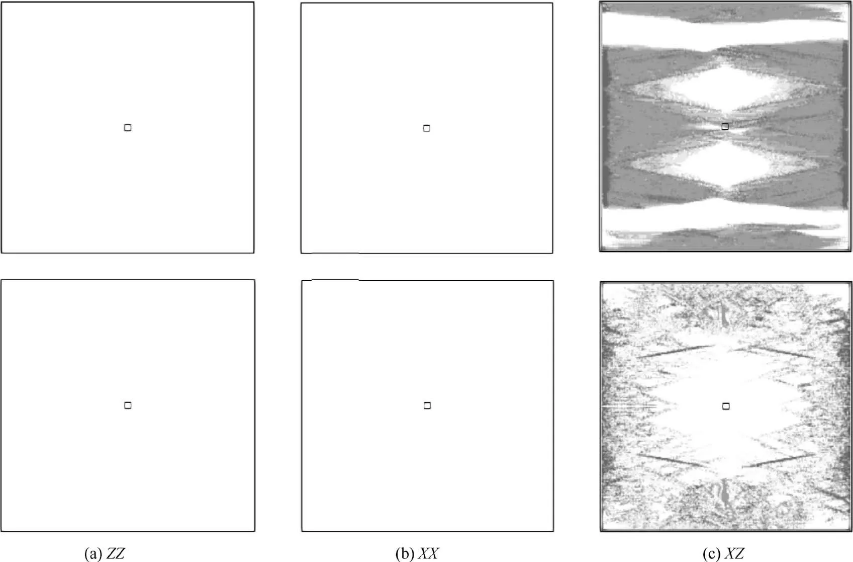
Fig. 3 Failure areas for a two-ply CFRP after an in-plane loading of 7.5 MPa. On top – the top ply, on bottom – the bottom ply.
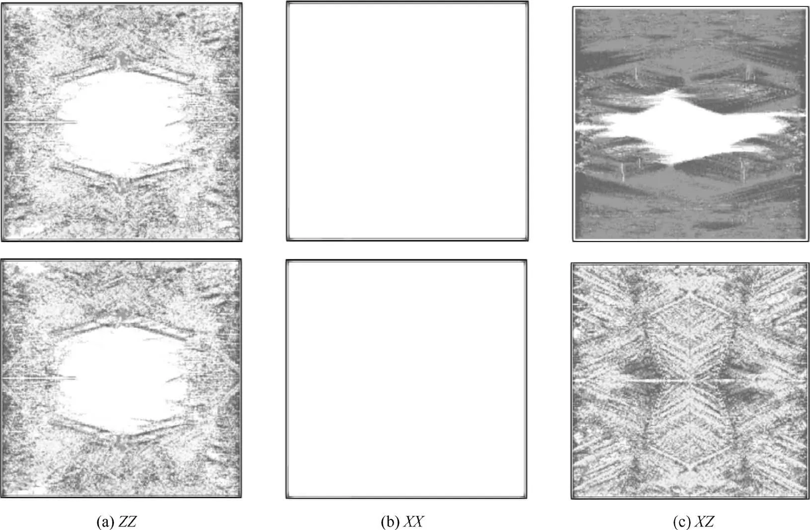
Fig. 4 Failure areas for a two-ply CFRP after an in-plane loading of 10 MPa. On top – the top ply, on bottom – the bottom ply.
The striker velocity was chosen so that the impact led to a damaged area which size is significantly larger than the size of the striker,but much smaller than the size of the plate.According to a wide range of experimental data,5,6,9this is a typical barely visible impact damage that is not visible by the naked eye and hard to detect with standard ultrasound equipment.Damaged area in the ZZ stacking sequence after the lowvelocity impact but before the quasi-static loading can be observed on Fig. 5(a) – the amplitude of quasi-static loading was too low to cause any damage. It has an elliptic shape,the bigger axis is along the fiber direction, which also qualitatively corresponds with experimental data.9Size and shape of damaged areas are similar in case of other stacking sequences and can be visible in the middle of the plate in other columns on Fig. 5.
In comparison with Figs.3 and 4 these figures show that in the presence of barely visible impact damage caused by a lowvelocity impact the resulting damage areas are larger, though the characteristic crack pattern after loading along and across the fiber direction remains the same.Even if the damaged areas from an impact and from a quasi-static loading are not connected(Fig.6(b)),the presence of damaged area in the middle of the specimen alters the elastic wave pattern and stress distribution during the loading and leads to a significant damage(Fig.4(b)).The failure measure corresponds to the matrix fracturing without fiber damage. Massive matrix fracturing can lead to appearance of macroscopic fractures that will grow during any consecutive loading.Damage that is appearing during the quasi-static loading can both propagate from the loaded side (Figs. 5 and 6(c), middle row) and from the damage caused by impact (Fig. 5(b)).
3.4. In-plane loading of CFRP, armed with a titanium layer
In this paragraph, destruction patterns for a two-ply CFRP,armed with a titanium layer,after a quasi-static in-plane loading with different amplitude are presented. In the first statement, no low-velocity impact is present.
Firstly, a laying in different directions was considered. On the Fig.7–a loading of 10 MPa.A loading with higher amplitude also leads to a full destruction of the sample. A loading with amplitude of 7.5 MPa and less doesn’t lead to any damage. Secondly, a single-direction laying was considered. On the Fig. 8 failure areas after an in-plane loading of 15 MPa are given. A loading with higher amplitude also leads to a full destruction of the sample. A loading with amplitude of 10 MPa and less doesn’t lead to any damage.
In the second statement, a low-velocity impact of a 5 mm×5 mm×5 mm titanium striker is considered.Destruction patterns for a two-ply CFRP,armed with a titanium layer,after a low-velocity impact of a 5 mm×5 mm×5 mm titanium striker and a quasi-static in-plane loading with different amplitude are presented.
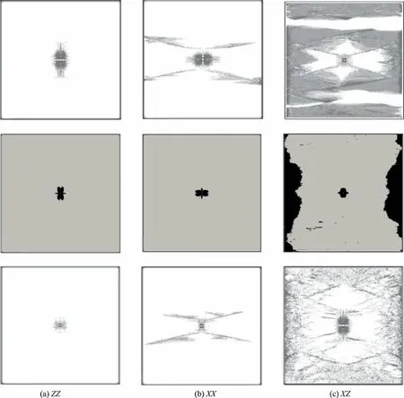
Fig. 5 Failure areas for a two-ply CFRP after a low-velocity impact of a 5 mm×5 mm×5 mm titanium striker with a velocity of 0.6 mm/sec and an in-plane loading of 7.5 MPa.On top–the top ply,in the middle–delamination(black areas),on bottom–the bottom ply.
Firstly, a different laying direction was considered. The amplitude of quasi-static in-plane loading was 5 and 7.5 MPa, which did not cause any damage without a lowvelocity impact. On Figs. 9 and 10 resulting failure areas are given for ZX and XZ stacking sequences and for 5 MPa loading. In the presence of the barely visible impact damage that was left after a low-velocity impact a damage after a quasistatic loading appears, and a stronger impact leads to a larger destruction of a specimen. The elliptic barely visible impact damage pattern is clearly visible in the middle of the specimen.Left columns on Figs.9 and 10 can be referenced for a damage pattern after the low-velocity impact but before the quasistatic loading, because it is too low to cause any additional damage.As you can see,the damage on the upper ply is significantly larger and includes two separate damaged areas – one directly beneath the striker and another that forms a wide ring around it. This damage pattern is dangerous, because one of the isolated areas can be missed during further examination.The order of laying is important in this statement because of the titanium layer that reinforces the composite plate under the quasi-static loading.
On Figs. 11 and 12 resulting failure areas are given for ZX and XZ stacking sequences and for 7.5 MPa loading. In that case, the amplitude of the low-velocity impact does not influence the resulting pattern as much as in other cases, but its presence even with a small amplitude still leads to a complete destruction of the specimen, while the same loading without a barely visible impact damage did not cause any damage to the specimen.
Secondly, a single-direction laying was considered. The amplitude of quasi-static in-plane loading was 10 MPa, which did not cause any damage without a low-velocity impact. On Figs. 13 and 14 resulting failure areas are given for ZZ and XX stacking sequences. In the presence of the barely visible impact damage that was left after a low-velocity impact a damage after a quasi-static loading appears, and after a stronger impact in case of ZZ stacking sequence (vertical axis on Fig. 13) it leads to a complete destruction of a specimen.The elliptic barely visible impact damage pattern is clearly visible in the middle of the specimen. In case of XX stacking sequence (horizontal axis on Fig. 14) even a weak lowvelocity impact leads to a loss of residual strength. Delamination patterns are not informative in this statement,and are not included in the paper.
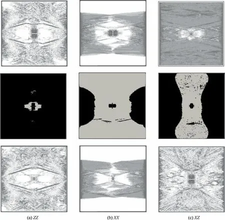
Fig. 6 Failure areas for a two-ply CFRP after a low-velocity impact of a 5 mm×5 mm×5 mm titanium striker with a velocity of 0.6 mm/sec and an in-plane loading of 10 MPa.On top–the top ply,in the middle–delamination(black areas),on bottom–the bottom ply.
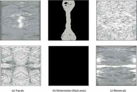
Fig.7 Failure areas for a two-ply CFRP,armed with a titanium layer after an in-plane loading of 10 MPa.On top–stacking sequence XZ, on bottom – stacking sequence ZX.
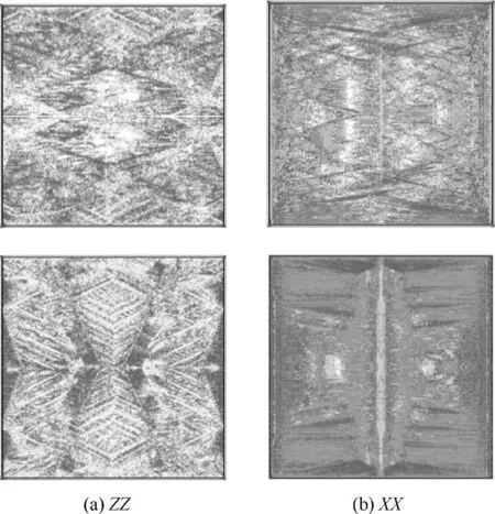
Fig.8 Failure areas for a two-ply CFRP,armed with a titanium layer after an in-plane loading of 15 MPa.On top–the top ply,on bottom – the bottom ply.
The ZZ stacking sequence shows better results (Fig. 13)than the XX stacking sequence(Fig.14)in the presence of titanium layer. Without the titanium layer (Figs. 4, 6), the XX stacking sequence showed lesser damaged areas.
4. Conclusions
A grid-characteristic numerical method, previously verified on experimental data in various statements, was applied for the study of residual strength of fiber and fiber-metal laminates.
(1) CFRP and CFRP armed with a titanium layer under a quasi-static loading and under a sequence of lowvelocity impact and a quasi-static loading were considered.
(2) Three-dimensional stress, velocity and damaged area patterns during the whole loading process were obtained for each statement.
(3) The analysis of numerical data show on a qualitative layer that the presence of barely visible impact damage after a low-velocity impact reduce the residual strength of fiber and fiber-metal laminates. This method, combined with experimental basis,can be used to determine quantitative parameters of strength deterioration of aviation composites after a low-velocity impact.
Declaration of Competing Interest
The authors declare that they have no known competing financial interests or personal relationships that could have appeared to influence the work reported in this paper.
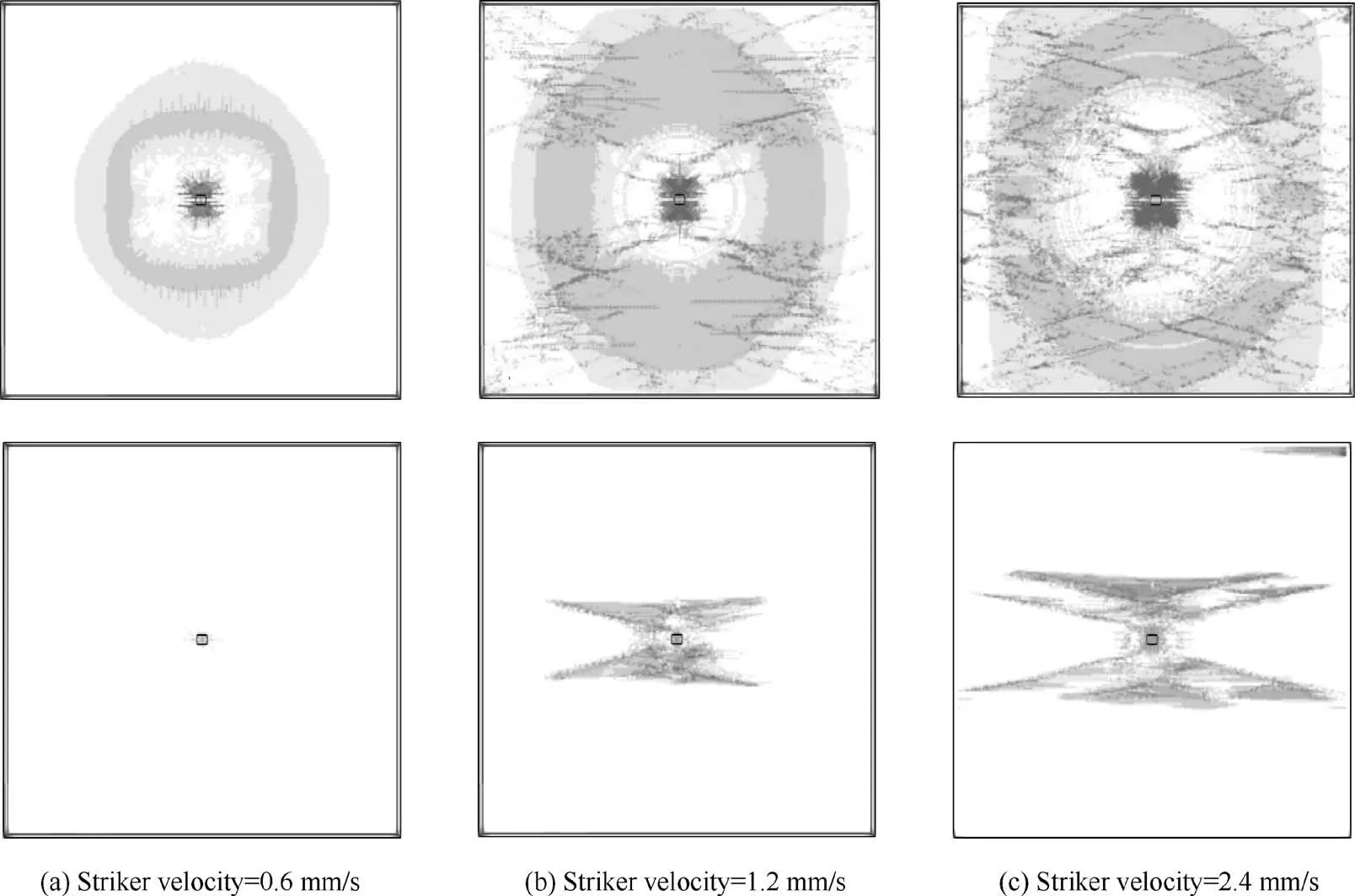
Fig. 9 Failure areas for a two-ply CFRP (XZ), armed with a titanium layer after a low-velocity impact of a 5 mm×5 mm×5 mm titanium striker and a quasi-static in-plane loading of 5 MPa. On top – the top ply, on bottom – the bottom ply.
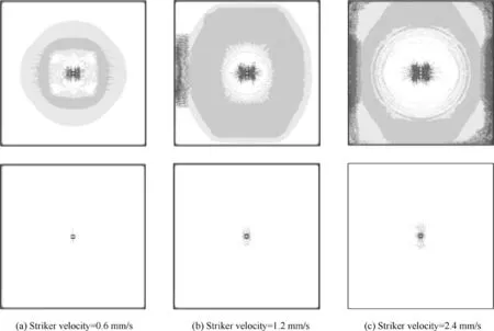
Fig. 10 Failure areas for a two-ply CFRP (ZX), armed with a titanium layer after a low-velocity impact of a 5 mm×5 mm×5 mm titanium striker and a quasi-static in-plane loading of 5 MPa. On top – the top ply, on bottom – the bottom ply.
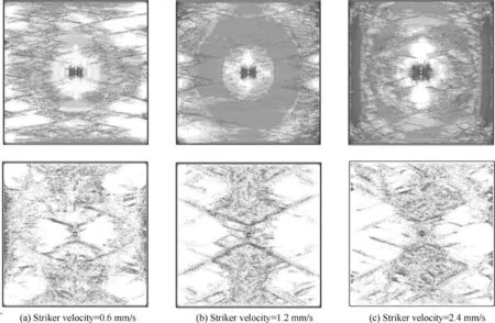
Fig. 11 Failure areas for a two-ply CFRP (XZ), armed with a titanium layer after a low-velocity impact of a 5 mm×5 mm×5 mm titanium striker and a quasi-static in-plane loading of 7.5 MPa. On top – the top ply, on bottom – the bottom ply.
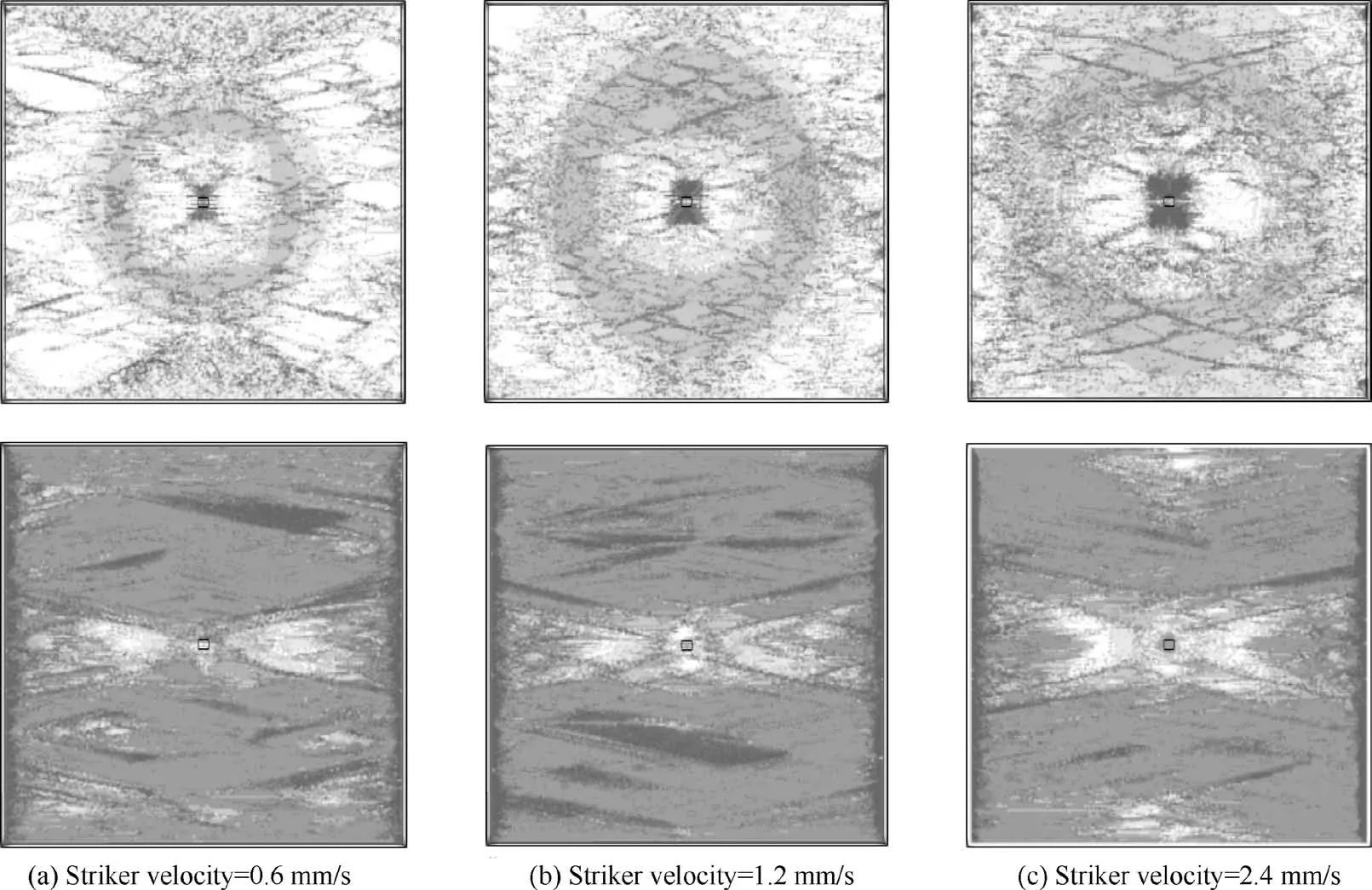
Fig. 12 Failure areas for a two-ply CFRP (ZX), armed with a titanium layer after a low-velocity impact of a 5 mm×5 mm×5 mm titanium striker and a quasi-static in-plane loading of 7.5 MPa. On top – the top ply, on bottom – the bottom ply.
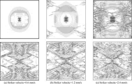
Fig. 13 Failure areas for a two-ply CFRP (ZZ), armed with a titanium layer after a low-velocity impact of a 5 mm×5 mm×5 mm titanium striker and a quasi-static in-plane loading of 10 MPa. On top – the top ply, on bottom – the bottom ply.
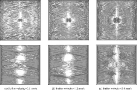
Fig. 14 Failure areas for a two-ply CFRP (XX), armed with a titanium layer after a low-velocity impact of a 5 mm×5 mm×5 mm titanium striker and a quasi-static in-plane loading of 10 MPa. On top – the top ply, on bottom – the bottom ply.
Acknowledgement
This work was carried out with the financial support of the Russian Science Foundation (No.19-71-00147).
 CHINESE JOURNAL OF AERONAUTICS2021年7期
- CHINESE JOURNAL OF AERONAUTICS的其它文章
- Integrated batteries layout and structural topology optimization for a solar-powered drone
- Polynomial networks based adaptive attitude tracking control for NSVs with input constraints and stochastic noises
- Morphing wing flaps for large civil aircraft:Evolution of a smart technology across the Clean Sky program
- Review on bio-inspired flight systems and bionic aerodynamics
- SARISTU:Adaptive Trailing Edge Device(ATED)design process review
- Continuous morphing trailing-edge wing concept based on multi-stable nanomaterial
