Experimental and numerical simulation of bird-strike performance of lattice-material-infilled curved plate
Jun YAN, Chengung ZHANG, Sixu HUO, Xinghi CHAI, Zhihui LIU,Kun YAN
a State Key Laboratory of Structural Analysis for Industrial Equipment, Department of Engineering Mechanics, Dalian University of Technology, Dalian 116024, China
b Ningbo Institute of Dalian University of Technology, Ningbo 315016, China
c Department of Discipline Engineering, AVIC Commercial Aircraft Engine Co., LTD, Shanghai 200241, China
d Shanghai Engineering Research Center of Civil Aero Engine, Shanghai 200241, China
e School of Chemical Engineering, Dalian University of Technology, Dalian, Liaoning 116024, China Received 30 June 2020;
revised 22 July 2020; accepted 31 August 2020
KEYWORDS Bird-strike test;Face-centered cubic lattice;Infilled curved plate;Lattice material;Numerical simulation
Abstract The anti-bird-strike performance of a lattice-material-infilled curved plate is investigated herein. Since automatically filling the curved structure by classical lattice material filling methods will cause a large number of manufacturing defects, a space-dependent lattice material filling method for the curved plate is firstly proposed in this paper Next,using a face-centered cubic lattice,a lattice-material-infilled test piece with a hollow ratio of 40.8% is built. The test pieces are manufactured via additive manufacturing using titanium alloy.In bird-strike experimental tests,the test pieces are crashed against gelatin birds at an impact velocity of 200 m/s.Dynamic strain gauges are used to record the crash history and the results are discussed.Furthermore,a numerical analysis to simulate the bird-strike experiment is performed. The results from the experimental tests and numerical simulation agree well. This work shows that the lattice-material-infilled curved plate yields promising bird-strike resistance.Therefore,lattice-infilled materials are feasible for protecting aerospace components against bird-strike as well as for reducing the component weight.
1. Introduction
Reducing the weight of structures can effectively improve the performance of many structures in aerospace, such as aeroengines and aircrafts. Infill structures are effective in reducing the weight of specific components and have been widely used in engineering applications. However, owing to limited manufacturing capabilities, the traditional corrugated infilled core design does not allow for a relatively high hollow ratio of structures, such as ratio higher than 40%. Fig. 1 shows an example of a corrugated infilled blade. Because of its high shear transferability and manufacturability, the corrugated infilled blade has been widely used in aeroengines. However,owing to the requirement of manufacturing precision control,the core layer has a lower limit in terms of thickness,resulting in an upper limit in the hollow ratio of the blade.
In recent years,with the improvement in additive manufacturing technology, more selections are afforded for the core layer designs. Among such options, lattice structures1–3are considered to be one of the most promising new-generation lightweight structure/functional integration materials in aerospace engineering.4The lattice material (as shown in Fig. 2),as a new advanced material containing porous ordered microstructure,5offers advantages such as high specific strength, high specific stiffness,6and excellent heat insulation and energy absorption capacity.7Owing to these advantages,lattice materials have been widely studied.8–11
Designability is another advantage of lattice material. The optimal design and layout of a lattice material depends on its performance requirements for specific structures.For many components in aerospace, such as the wings of an aircraft and the blades of an aero-engine, the anti-bird-strike performance is one of the key performance indicators. The civil aviation regulations of many countries have stipulated detailed requirements for the performances of aircrafts and engines in birdstrike. However, conducting bird-strike experiments with real structures are extremely expensive. Hence, equivalent simulation members are often used to test the anti-bird-strike performance of new structural designs in advance. After the equivalent component successfully passes the bird-strike experiment, the new design can be further considered for aerospace components. Wang et al.12introduced additional parameters to define the microstructure cell pattern and its uneven distribution.Wang et al.13used LS-DYNA to simulate the dynamic behaviors of PMMA aircraft windshield under high-speed bird-strike and compared with the test.Liu et al.14,15proposed a design method for bird-strike-resistant aircraft structures,they used the coupled SPH-FE method to numerically simulate the bird-strike test, and established a numerical model using the commercial software PAM-CRASH. Duan et al.16investigated low-speed and high-speed experiments and numerical studies on the dynamic responses of continuous graded foams.
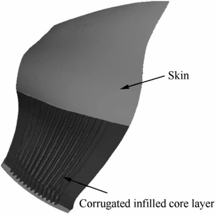
Fig. 1 Fan blade with corrugated infilled core layer.
Owing to the excellent energy absorption of lattice materials, the performances of lattice materials in impact problems have been studied extensively. Xue and Hutchinson,17,18studied the performance of metal-sandwiched panels of pyramidal trusses,square honeycombs,and folded plates under impulsive blast loads and compared it with that of solid plates made of the same material and having the same weight. Sanders and Gibson19analyzed the elastic modulus and initial yield strength of hollow ball foams of body-centered cubic and face-centered cubic infills and discovered that the latter design had a higher specific modulus and strength. Qiu et al.20proposed an analysis model of a lattice sandwich beam subjected to an impact load at the center and found that a prismatic diamond core sandwich beam provides the best performance.Tilbrook et al.21studied the dynamic mechanical properties of corrugated and Y-shaped lattice structures under a low-speed impact. Wei et al.22theoretically studied a multilayer pyramid lattice sandwich plate under an impact load and verified it using the finite element method. Liang et al.23studied the performances of sandwich panels with square honeycombs, Ishaped cores, and corrugated cores under impact loads. Tang et al.24studied the dynamic compressive behavior of aluminum-alloy-based tetrahedral-core truss structures.Rubino et al.25performed a dynamic impact test and numerical analysis on corrugated and Y-shaped lattice structures.Yungwirth et al.26,27discovered that a lattice structure with embedded parts offers high impact resistance and energy absorption. Wang28performed low- and high-speed impact tests as well as numerical simulations on a composite pyramid lattice sandwich structure. Ying et al.29discovered that the face-centered cubic structure demonstrated stronger energy absorption based on an impact performance test. Cui et al.30theoretically and experimentally investigated the impact behavior of the metal pyramid lattice structure.By performing dynamic compression experiments,Fan et al.31discovered that compared with quasi-state compression, the compression strength and energy absorption capacity of a composite pyramid lattice sandwich structure improved significantly. Guo et al.32compared the dynamic responses obtained by repeated impact tests of aluminum foam sandwich plates through numerical simulations and discovered that the results agreed well.
To verify the applicability of lattice materials to components required to assess the anti-bird-strike ability, the birdstrike resistance performance of a curved plate was investigated in this study. In simulations, a curved plate can be used to model the wings of an aircraft or the blades of an aero engine. In this study, the curved plate was developed by extruding the cross section of an aero engine blade. Because the hollow space of the curved plate is irregular, classic lattice-material-infilled approaches may produce a large number of manufacturing defects.Hence,a space-dependent lattice material filling method is proposed in this paper.Furthermore,for manufacturing and numerical analysis,two effective methods for modeling a lattice-material-infilled curved plate were further proposed. Using these proposed approaches, we constructed a test piece that exhibited a face-centered cubic lattice.The hollow ratio of the test piece was 40.8%. The test pieces were made of titanium alloy and manufactured via additive manufacturing. In the bird-strike experimental tests, the test pieces were crashed into by gelatin birds at an impact velocity of 200 m/s. Seven dynamic strain gauges were evenly distributed on the surface of the test piece, and the structural response histories were recorded during the impact. Furthermore, we performed a numerical analysis to simulate the bird-strike experiment. In the numerical analysis model, we used a mixed finite element model to reduce the computing time. Finally, the results from the experiment and numerical analysis are discussed, and the conclusions are provided.
The remainder of this article is organized into four sections:The method of modeling the lattice-material-infilled structure is described in Section 2. The bird-strike experimental tests and their results are presented in Section 3.The numerical simulation of the bird-strike process and the numerical analysis results are provided in Section 4. Finally, the conclusions are presented in Section 5.
2. Modeling of lattice-material-infilled curved plate
This section first describes the structural design of the latticematerial-infilled curved plate. Next, the finite element model modeling and geometric modeling methods of the latticematerial-infilled curved plate are introduced. Finally, the design parameters of the test piece used in the experimental tests and numerical simulations are presented.
In this study, we adopted the face-centered cubic lattice to fill the core layer of the curved plate. This is because the facecentered cubic lattice exhibits good shear transfer ability and high specific strength. The structure of the face-centered cubic lattice (as shown in Fig. 4) is controlled by the distance D,height H, length L, section diameter d, and tilt angle θ.Fig. 5 shows the test piece design used in the experiment and numerical simulation.
2.2. Modeling method of geometric and finite element models
Several challenges will be encountered when modeling the lattice-material-infilled curved plate exactly. These challenges may also occur when modeling lattice-material-infilled aerospace components.
First, the irregular filling space may cause problems in lattice filling. In practical applications, the modeling of latticematerial-infilled structures is usually realized using commercial software. The commercial software creates lattice structures based on a fixed-coordinate system and uses uniformly distributed and sized lattices. However, for complex structures,because the core layer of the curved plate is not of a regular geometric shape,the uniform lattice-material-infilled approach will generate many broken lattices (as shown in Fig. 6), which may significantly affect the structural stiffness or strength as well as significantly increase the risk of manufacturing defects.
Hence, a shape-dependent lattice material filling approach was proposed here and used to ensure the integrity of all the cells, thereby reducing the risk of manufacturing defects. In a shape-dependent unit cell, the height H of each cell changes with the filling space size, as shown in Fig. 5.
To analyze and evaluate a lattice infill design, numerical analysis is necessary and hence widely used. Traditionally, a geometric model is first generated before simulation; subsequently, a FE (finite element) model is generated based on the geometry model to perform the numerical analysis of the lattice-material-infilled structure. Herein, a FE solid mesh was first constructed according to the geometry of an extruding curved plate; subsequently, a geometry model was constructed based on the mesh information. Flow charts of the FE modeling and geometric modeling methods are shown in Fig. 7.
To create a FE model for structural evaluation, we used a model comprising solid (for upper and lower surfaces) and beam elements (for internal lattice infill structures) instead of a total solid element model. Because numerous tiny structures(such as rods) exist in the lattice-material-infilled structure, if
2.1. Lattice-material-infilled curved plate
The lattice-material-infilled curved plate comprises two parts:the external solid structure and the internal lattice material.The external entity structure is obtained by extruding the cross section of external entity structure of a corrugated infilled wide-chord fan blade,which is shown in Fig.1.The cross section used for extruding is the cross section at 70% from the root of the blade, and the extruding length is 285 mm, as shown in Fig. 3. Therefore, the curved plate retains the structural features of the fan blade to the greatest extent; however,the equivalent simulation member is more complicated than the regular plate.solid elements are used to discretize the structure,the finite element model will contain many relatively small elements.Moreover,in explicit dynamic analysis,which is widely used in crash analysis,the time step length depends on the feature size of the smallest element in the finite element model. Therefore, when the lattice-material-infilled curved plate is meshed by solid elements,the scale of the analysis model as well as the number of analysis steps will be extremely large, thereby resulting in an unaffordable computational cost.
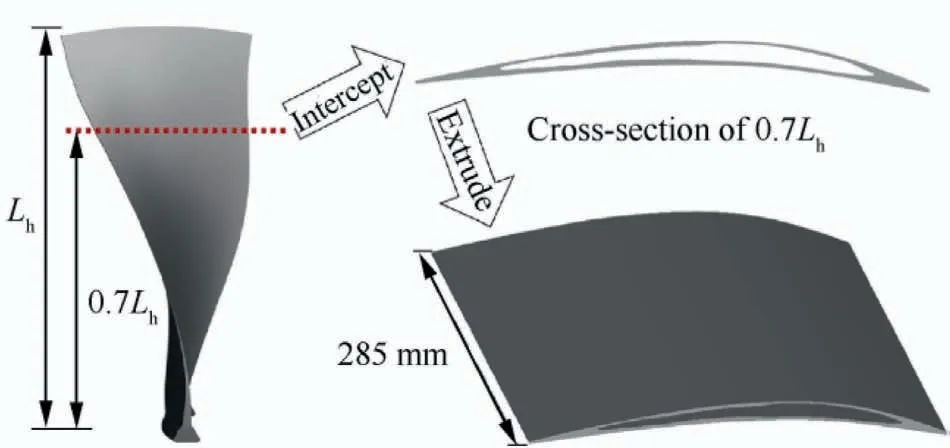
Fig. 3 Curved hollow plate model (Cross section is extracted at 70% from root of blade; extruding length is 285 mm).
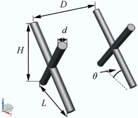
Fig. 4 Face-centered cubic unit cell and its main geometric parameters.
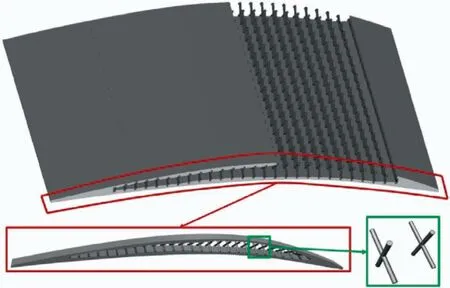
Fig. 5 Structural design of lattice-material-infilled curved plate.
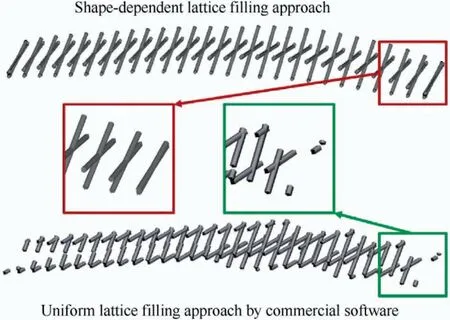
Fig. 6 Difference of different filling methods.
2.2.1. Modeling method of finite element model of the latticematerial-infilled curved plate
To reduce the computing time of numerical simulation, the mixed finite element model of solid and beam elements was used in this study. The modeling process used in this study is as follows:
Step 1: Mesh the outer solid structure based on the steps shown in Fig. 8. Hence, the solid elements will have the same size along the extrude direction of the curved plate;this is necessary for the lattice filling step. Meanwhile, the size of each element in such a solid mesh is relatively uniform; thereby extremely small elemental features are avoided.
Step 2: Fill the lattice material in the solid finite element model with beam elements based on the steps shown in Fig. 9: (a) Extract all node information of the inner surfaces of the solid mesh; (b) Select two adjacent nodes from each set of nodes on the two inner surfaces to be used as the four endpoints of the unit cell, and calculate the locations of the midpoint using Eq. (1); (c) Connect the four endpoints with the midpoint by straight lines; (d) Mesh all the lines using beam elements. The expression of Eq. (1) is

where xc, yc, and zcare the spatial coordinates of the central node;xi,yi,and ziare the position coordinates of the i-th node;The summation of 4 means the 4 nodes of one face-centered cubic lattice. The lattice infill of the test piece is shown in Fig. 9.
Another advantage of the modeling method above is that the constraint of the printing direction can be easily satisfied by using suitable nodes on the surfaces of the solid mesh model. Furthermore, it was discovered that after the meshing of the outer solid model was completed, the node sets on the inner surfaces of the solid mesh model were the potential vertex positions of the lattice cells. Therefore, the denser the grid of the solid elements,the richer the placement of the unit cells.Although only face-centered cubic lattices were considered in this study, other types of the unit cell can in fact be modeled similarly, barring the requirements and number of node selections.
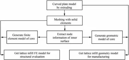
Fig. 7 Flow chart of modeling methods of geometry model (for manufacturing) and FE model (for structural evaluation).
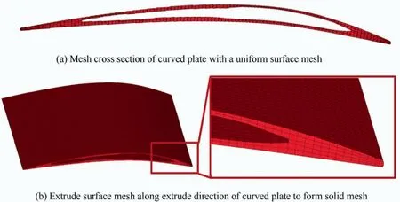
Fig. 8 Step 1 of finite element model modeling.
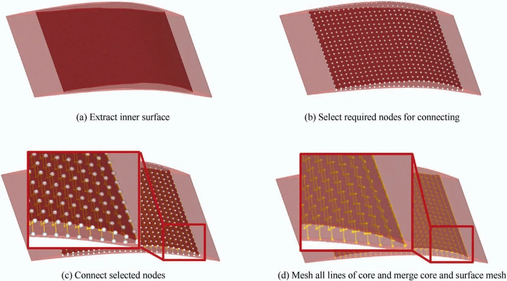
Fig. 9 Step 2 of finite element model modeling.
2.2.2. Modeling method of geometric model of the latticematerial-infilled curved plate
The geometric model was composed of two parts:the external entity and the lattice infill structure. The geometric model of the external entity structure model was constructed before lattice material filling was performed. Therefore, only the geometric model of the lattice-material-infilled structure needed to be constructed. Based on the node information and section parameters of the finite element model of the lattice material,a geometric model of the core layer of the lattice-materialinfilled structure can be constructed easily. Subsequently, the entire geometric model can be obtained by merging these two parts through Boolean operations. The modeling procedures are shown in Fig. 10.
2.3. Introduction of test piece
The test piece used in the experiment and numerical simulation is shown in Fig. 11, where D was set to 5.4 mm, L to 9.5 mm,and d to 1.7 mm. As introduced in the previous section, the height of each unit cell varied with the height of the core layer.The hollow ratio η represents the ratio of the hollow domain to the volume of the full model. It is widely used to represent the removed weight. For the same material, a larger the hollow ratio means a smaller weight of the curved plate structure. In this study, the hollow ratio was calculated as follows:

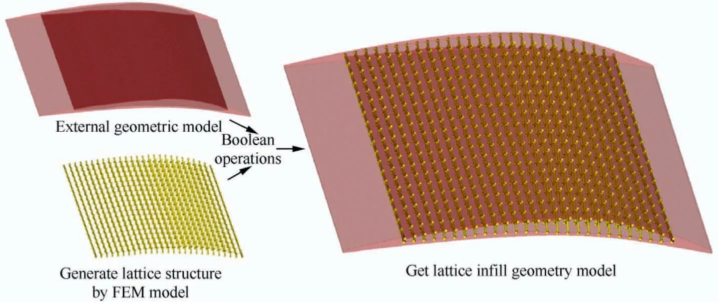
Fig. 10 Geometric model modeling of lattice-material-infilled curved plate.

Fig. 11 Schematics of test piece cross-section.
where Vsis the volume of the hollow domain, and V0is the volume surrounded by the external surfaces of the curved plate structure.
Based on Eq. (2), the hollow ratio of the test pieces in the experimental test was 40.8%. It is noteworthy that traditional core layer features can barely achieve such a high hollow ratio.For example, if a corrugated plate core is adopted to fill the curved plate,as shown in Fig.1,when the core layer thickness is set to 1 mm, the hollow ratio of the corrugated infilled curved plate will be only 34.7%. However, the design ability of the lattice structure offers the opportunity for structural optimization to obtain a design with a higher hollow ratio.
3. Experimental tests
A bird-strike experiment was performed to test the bird-strike resistance of the test pieces.In a bird-strike test,the test pieces can withstand the impact of the bird body in a stationary state.
3.1. Experimental setup
The setup for the experimental test is shown in Fig.12;it comprises an air cannon system,a laser speed measurement system,a high-speed camera, and a multichannel data acquisition system. The air cannon system enables the gelatin bird body to impact a specific position on the test piece at a predetermined speed and direction.
The bird speed is obtained using the following expression:

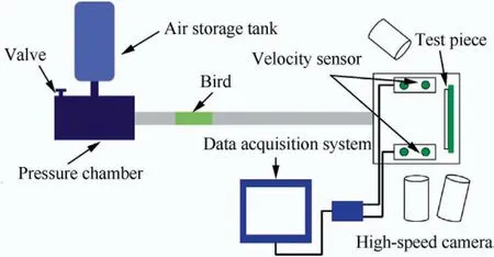
Fig. 12 Arrangement of experimental test equipment.14
where L is the distance between two light sensors,and TLis the flight time of the bird through the two light sensors.As shown in Fig. 13, both ends of the test pieces were clamped by fixtures, but they are slidable in the extruding direction. The crash angle was set to 30°±0.5°.
Six strain measurement points and seven strain gauges were arranged on the test piece, as shown in Fig. 14. Among them,both strain gauges 2 and 3 were attached to the center of the curved plate surface; however, they were oriented perpendicular to each other. Strain gauges 1 and 5 were placed at two points that were symmetrical to the transverse extension of strain gauge 2 as the central axis and 40 mm away from the center point, wherein the longitudinal strain was measured.Strain gauge 4 was placed 40 mm from the axial extension of strain gauge 3 and was used for longitudinal strain measurement. Strain gauges 6 and 7 were placed at the interface between the solid and hollow parts of the plate,and the transverse strains at these parts were measured.
3.2. Experimental results
The crash process between the gelatin bird body and the test piece is shown in Fig. 15.
To ensure the accuracy of the test,the same experiment was performed twice. The bird’s weight and impact velocity differed slightly. In the first experiment, the bird’s weight was 549 g, and the impact speed was 203 m/s; and in the second experiment, the bird’s weight was 548 g, and the impact speed was 201 m/s. The slight differences did not significantly affect the experimental results, and the test data of the two experiments indicated good consistency.
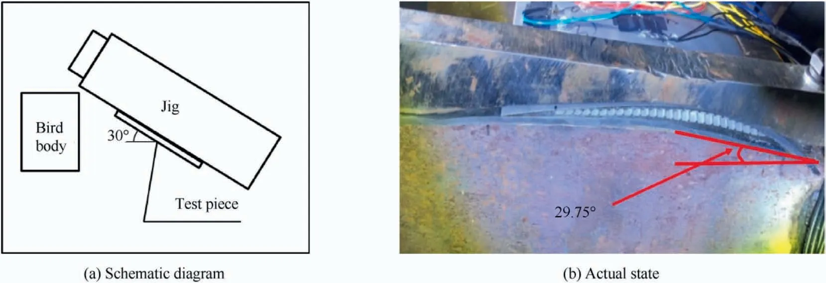
Fig. 13 Crash angle of test pieces.
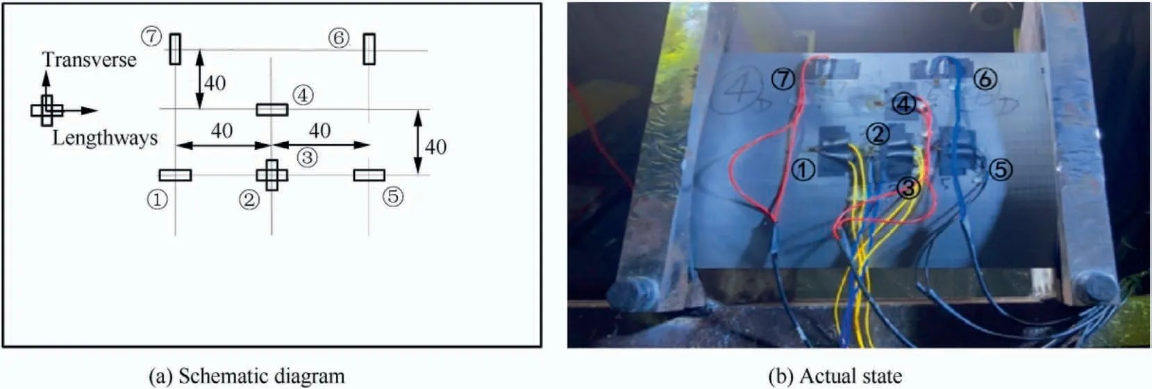
Fig. 14 Positions and directions of strain gauges.
Fig.16 shows the state of the test piece before and after the test. Fig. 17 shows the strain histories of each strain gauge obtained from the two experiments. It was discovered that strain gauges 1, 3, 4, and 5 recorded positive strains, implying that they were stretched during the crash.This implies that the entire structure underwent an overall bending deformation during the bird-strike. Meanwhile, strain gauges 2, 6, and 7 provided negative strains, i.e., they were compressed during the crash, indicating that the structure was compressed along the impact direction.
As shown in Fig.17, the different curves terminated at different time points.This is because during the crash test,owing to cable failure or strain gauge failure, data abnormalities occurred in the later stage of the test. To avoid confusion,we deleted the abnormal data when constructing the curves.
From the experimental data,it was discovered that because strain gauges 6 and 7 were the closest to the impact position,their response to collision occurred much earlier compared with other strain gauges. However, their strain values were much lower than those of other strain gauges.This means that the area where strain gauges 6 and 7 were located did not contribute significantly to the energy absorption of the structure.By contrast,strain gauges 1,3,4,and 5 indicated much higher strain values. This means that the area where these strain gauges were located absorbed a significant amount of energy during the bird-strike. The results above indicate that the entire structure(i.e.,not only the impact area)must be considered in structural design of the anti-bird-strike capability.
4. Numerical simulation
This section introduces the modeling method and provides the analysis results of the bird-strike numerical simulation.
4.1. Numerical model
In this study, commercial software LS-DYNA33was used as the numerical simulation analysis tool for the bird-strike experiment. The gelatin bird bodies were modeled using the Smoothed Particle Hydrodynamics (SPH) method. The SPH is a Lagrangian meshless particle method that can describe the physical state of a continuous medium body under highspeed impact conditions.34
4.1.1. Bird body model and material properties
The gelatin bird model used in the experiment was cylindrical and measured 108.3 mm in length and 80.53 mm in diameter.In the numerical simulation, the bird body was scattered into 96540 SPH particles. The material parameters of the gelatin bird body in the numerical simulation are listed in Table 1.
The MAT_NULL material model in LS-DYNA was selected for the SPH model because it enables the state equation shown in Eq. (4) and viscosity parameters to be used in numerical simulation.The SPH parameters used in the numerical simulation are shown in Table 2.

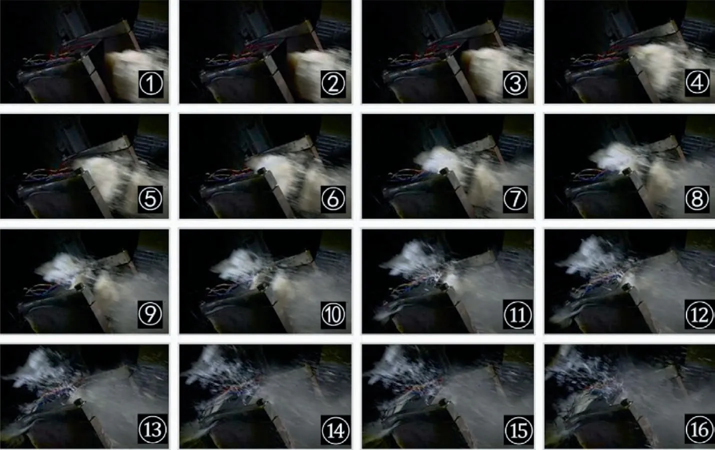
Fig. 15 Crash process of bird-strike (number on pictures means typical time step of crash process).
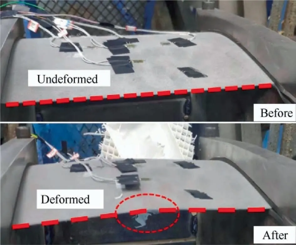
Fig. 16 Test piece status before and after bird strike test.

Table 1 Material parameters of gelatin bird body.
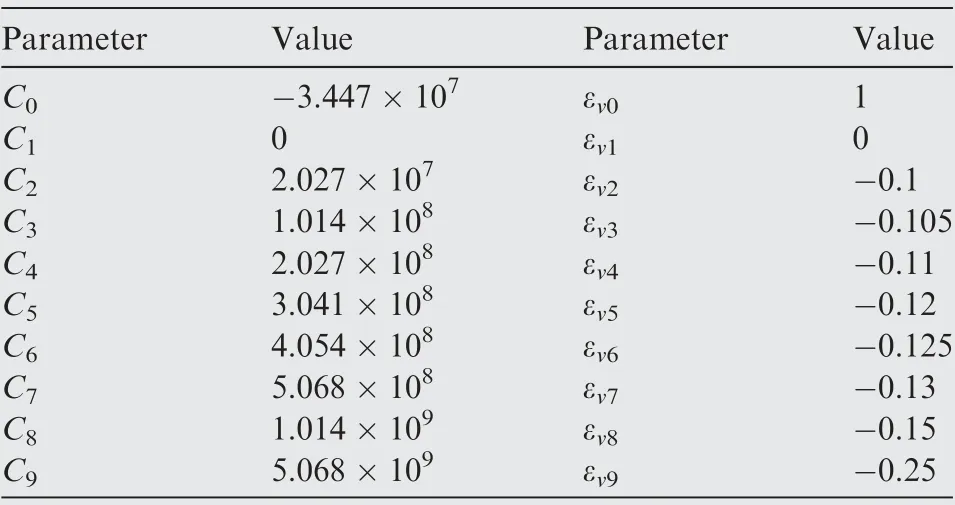
Table 2 Parameters of state equation of SPH model.
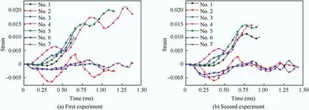
Fig. 17 Strain histories of two experiments during bird-strike.

Table 3 Parameters of quasi-static mechanical properties.

Table 4 Mechanical properties of strain-rate-related materials.
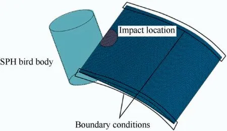
Fig. 18 Bird-strike analysis based on SPH.
4.1.2. Material model of test piece
Because the crash speed was set to a relatively high value(200 m/s), the strain rate effect could not be ignored in the numerical simulation. In this study, a bilinear plastic model was used. The following expressions describe the model:

where σyis the stress, σ0is the yield strength, ˙ε- the equivalent strain rate,ε-p the equivalent plastic strain,Epthe tangent modulus, Eethe young modulus and Etthe hardening modulus. It is noteworthy that the material model used involves the strain rate effect.
The parameters of titanium alloy TC4 were obtained in advance via parameter fitting based on the 3D printing material samples fundamental experimental test data, including the constitutive model parameters related to the material strain rate. The parameters are summarized in Tables 3 and 4. The equivalent critical strain of the materials was 0.18.
As mentioned above,the finite element model in the numerical simulation was a mixed model of solid and beam elements.All the internal lattices were modeled by beam elements.However,the beam element in LS-DYNA cannot consider the plastic effect; hence, the stiffness of the core layer will be overestimated. Therefore, the failure condition shown in Eq.(7) was introduced to the beam elements, i.e., when the maximum principal strain of some beam elements is greater than a predetermined value during the transient dynamic analysis,these beam elements will be deleted from the analysis model.

where ε1represents the principal strain,and εmaxrepresents the maximum principal strain.
4.1.3. Numerical analysis settings
The finite element model used in the analysis is shown in Fig.18.The outer entity part was meshed using eight-node linear solid elements with a total of 54840 elements. The core layer was meshed using 37140 beam elements.
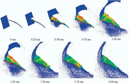
Fig. 19 Structural deformation and Mises stress distribution at various moments during bird-strike.
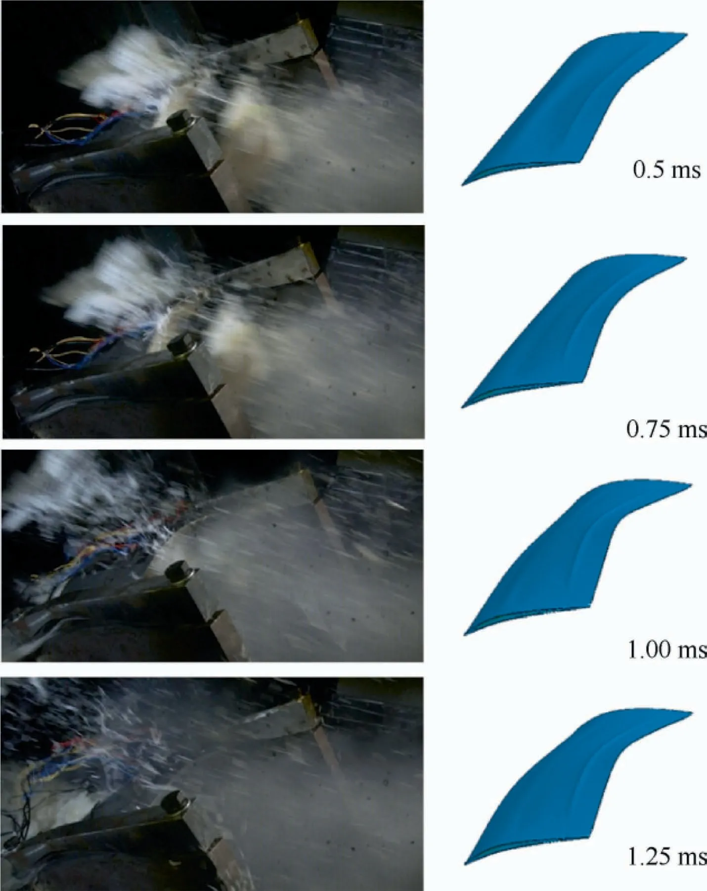
Fig. 20 Comparison between experimental and numerical deformations after 0.5, 0.75, 1.0 ms, and 1.25 ms.
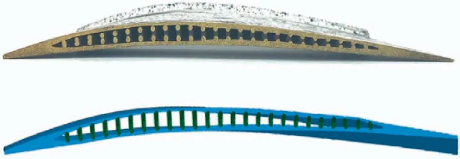
Fig. 21 Internal condition of curved plate after impact and simulation comparison.
The boundary conditions in the numerical simulation were the same as those in the experiment, i.e., the two ends of the test piece were clamped and constrained, but they can move freely in the length direction, as shown in Fig. 18. The initial speed of the SPH bird body was 200 m/s, and the crash angle was 30°.
Two sets of contacts were defined. The first one was the frictionless surface contact between the bird body and the plate.The second was the contact between the beam and solid elements for preventing the beam elements from penetrating the inner surface of the curved plate.
4.2. Simulation results
Fig.19 shows the structural deformation and Mises stress distribution at various moments during bird-strike obtained from numerical simulations.
Fig. 20 shows a comparison of the structural deformations of the test pieces in the experiment and numerical simulation.It was discovered that the structural deformation in the numerical analysis was consistent with the structural deformation in the experimental test. In addition, we cut the lattice-materialinfilled curved plate at the position deformed due to impacting of the test piece to observe the internal rods and extracted the corresponding simulation results as shown in Fig.21.It can be found that there is no obvious damage or breakage of the inner rods.
The strain histories at the locations where the strain gauges were placed were extracted from the numerical simulation. A comparison of strain histories of each strain gauge obtained experimentally and through numerical simulation is shown in Fig. 22. Each figure depicted in Fig. 22 contain three curves.The curves with triangle and circle markers show the experimental results, whereas those with square markers show results from the numerical simulations.For strain gauges 1,2,3, 4, and 5, the numerical simulation results agreed well with the experimental data. While, for strain gauges 6 and 7, the results exhibited relatively large differences. However, the strain values recorded by gauges 6 and 7 were considerably lower than those recorded by the other gauges; therefore, the area where strain gauges 6 and 7 located was not the most dangerous, and the numerical analysis errors can be accepted in general.
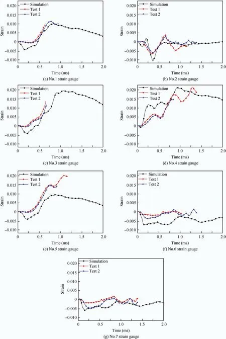
Fig. 22 Comparison between experimental and numerical strains.
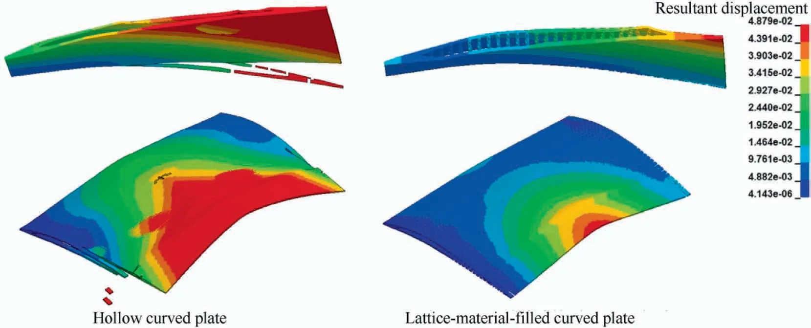
Fig. 23 Residual deformations of a hollow curved plate (left) and a lattice-material-infilled curved plate (right).
The deflection of bird body is one reason which causes differences between experimental results and numerical results.The bird body deflected during the strike;however,the deflection angle could not be accurately controled, resulting in a deviation between the actual bird strike load and the simulation load. In addition, the homogeneous isotropic material assumption, the material constitutive model and material parameters adopted in simulation would also cause differences between numerical results with experimental results.The third reason is because of cable failure or strain gauge failure,experimental data are less than the numerical data.
To show the role of the core layer of the lattice-materialinfilled curved plate, a bird-strike analysis was performed on the hollow curved plate (no core layer). The residual displacement distributions of the hollow plate and the lattice-materialinfilled plate are compared in Fig.23.It can be found that the hollow curved plate has much more obvious wrinkles and collapsed deformation.On the other hand,since the core layer of the lattice-material-infilled curved plate has good shear force transmission capability, the lattice-material-infilled curved plate has relatively better overall structural stiffness. This means that the lattice-material-infilled design absorbed impact energy through the overall deformation and avoids excessive local deformation which easily causes cracks. Compared with the other core layer designs, the advantage of the latticematerial-infilled design is that it can realize a structure with a relatively higher hollow ratio. Therefore, the latticematerial-infilled curved plate not only has good bird-strike resistance, but also can achieve a lightweight structure.
The results above imply that for the bird-strike test of the lattice-material-infilled structures, the structural response can be predicted with a relatively high precision through numerical analysis.Thus,the structural optimization design of the latticematerial-infilled structures can be based on the numerical analysis. Therefore, the design cost of lattice-material-infilled blades can be reduced significantly.
5. Conclusion
A lattice-material-infilled curved plate configuration is proposed for aerospace applications. The anti-bird-strike performance of the plate was evaluated in this study as a preliminary test of the suitability of lattice-material-infilled components. To overcome problems associated with the modeling and analysis of the lattice-material-infilled curved plate,a new modeling method is proposed to cope with the issues.The following results or conclusions can be drawn from this research:
(1) Using the proposed modeling methods,a test piece for a lattice-material-infilled curved plate with a high hollow ratio of 40.8% is obtained. And the pieces can be manufactured via additive manufacturing.
(2) In the bird-strike experimental tests,the test pieces were crashed by gelatin birds with an impact velocity of 200 m/s. The results indicated that the pieces successfully withstood bird impact without visible damage.
(3) Additionally, we recorded the dynamic strain responses of the pieces in the bird-strike experiment.Furthermore, we performed a numerical analysis to simulate the bird-strike experiment. The experimental tests and numerical simulations agreed well, implying that the structural design of lattice materials can be determined based on numerical analysis. This will significantly reduce the design cost of lattice-materialinfilled blades.
In summary, the results demonstrated that the latticematerial-infilled curved plate exhibited good bird-strike resistance and potential of lightweight design. This means that the lattice-material-infilled wide-chord fan blade is worthy of further developments. Finally, the proposed approaches are applicable to studies regarding optimization design of components in aerospace.
Declaration of Competing Interest
The authors declare that they have no known competing financial interests or personal relationships that could have appeared to influence the work reported in this paper.
Acknowledgments
Financial supports for this research were provided by National Key R&D Program of China (2018YFB1106400), National Natural Science Foundation of China (11672057, 11702052,U1906233), Aeronautical Science Foundation of China(2018ZB63002) and China Postdoctoral Science Foundation(2018M640251, 2019T120201). These supports are gratefully acknowledged.
 CHINESE JOURNAL OF AERONAUTICS2021年8期
- CHINESE JOURNAL OF AERONAUTICS的其它文章
- A novel virtual material layer model for predicting natural frequencies of composite bolted joints
- Multi-layered plate finite element models with node-dependent kinematics for smart structures with piezoelectric components
- Modeling bending behavior of shape memory alloy wire-reinforced composites: Semi-analytical model and finite element analysis
- Sequential ensemble optimization based on general surrogate model prediction variance and its application on engine acceleration schedule design
- Transition prediction and sensitivity analysis for a natural laminar flow wing glove flight experiment
- Modeling on mechanical behavior and damage evolution of single-lap bolted composite interference-fit joints under thermal effects
