Multi-layered plate finite element models with node-dependent kinematics for smart structures with piezoelectric components
Guohong LI, Erasmo CARRERA, Yuliang HOU, Gennady M. KULIKOV
a MUL2 Group, Department of Mechanical and Aerospace Engineering, Politecnico di Torino, Torino 10129, Italy
b Laboratory of Intelligent Materials and Structures, Tambov State Technical University, Tambov 392000, Russia
c School of Mechanical and Power Engineering, Zhengzhou University, Zhengzhou 450001, China
KEYWORDS Finite element;Laminated composites;Piezoelectric;Refined plate theory;Smart structures
Abstract This article presents a type of plate Finite Element(FE)models with adaptive mathematical refinement capabilities for modeling laminated smart structures with piezoelectric layers or distributed patches. The p-version shape functions are used in combination with the higher-order Layer-Wise (LW) kinematics adopting hierarchical Legendre polynomials. Node-Dependent Kinematics(NDK)is employed to implement local LW models in the regions with piezoelectric components and simulate the global substrate structure with the Equivalent Single-Layer(ESL)approach.Through the proposed NDK FE models,the electro-mechanical behavior of smart structures can be predicted with high fidelity and numerical efficiency, and various patch configurations can be conveniently modeled through one set of mesh grids. Moreover, the effectiveness and efficiency of the NDK FE approach are assessed through numerical examples and its application is demonstrated.©2021 Chinese Society of Aeronautics and Astronautics.Production and hosting by Elsevier Ltd.This is an open access article under the CC BY-NC-ND license(http://creativecommons.org/licenses/by-nc-nd/4.0/).
1. Introduction
Electro-mechanical coupling is a reversible process in which an electrical field causes straining (direct effect),and deformation causes an electric potential (reverse effect). Such coupling effects are the main characteristics of various piezoelectric materials, which have been used as sensors and actuators in a great variety of smart structures. Piezoelectric components,either patches or layers, are usually bonded to the surfaces or embedded in the structures.
The key problem of piezoelectric modeling is to capture the mechanical interaction between the local piezoelectric devices and the substrate structures.Given the features of smart structures with piezo-patches or layers,a direct modeling approach is to use brick elements, as suggested by Batra and Liang,1Hauch,2and Tzou and Tseng.3However,due to the limitation of the aspect ratio of solid elements,it is widely agreed that 3D Finite Element(FE)modeling is comparatively computational expensive in the simulation of thin piezoelectric components than using beam and plate elements.
A wide variety of piezoelectric beam and plate elements have been proposed. Models in the Equivalent-Single-Layer(ESL) approach consist of the Classical Laminated Theory(CLT), First-order Shear Deformation Theory (FSDT), and Higher-Order Theories (HOT). In such models, the number of unknowns depends only on the kinematic assumptions.The works of Wang and Rogers4and Tzou and Gadre5are examples of induced strain models based on CLT for smart plates and shells with distributed actuators,respectively.However, the coupled electro-mechanical responses cannot be captured since the electric potential is not considered as an independent variable. In the plate element based on CLT developed by Hwang and Park,6an electrical Degree of Freedom (DOF) was included, and distributed actuators and sensors were both considered. Chandrashekhara and Agarwal7developed elements adopting the FSDT for plates with both sensors and actuators without introducing the electric potential as an additional DOF. In the plate elements adopting FSDT developed by Batra,8Suleman and Venkayya,9and Huang and Wu,10the fully coupled electro-mechanical governing equations were considered. ESL models are intrinsically easy to formulate,but the interlaminar continuity of transverse stresses and traction free boundary conditions are not ensured.The zig-zag models were suggested to overcome these drawbacks.A historical review of the zig-zag models was presented by Carrera.11To formulate efficient electro-mechanical plate elements, Cho and Oh12adopted the third-order zig-zag model.
In the Layer-Wise (LW) approach,13the number of unknowns depends on the number of layers. Robbins and Reddy14suggested two ESL and two LW displacement-based FE beam models to investigate the piezoelectric actuation of laminated beams. It was pointed out that using simplified stress fields in the composite structure may not well represent the transverse stresses near the free ends,and the suggested linear LW beam theory can satisfy the traction-free boundary conditions. To take advantage of the ESL and LW approaches, a hybrid ESL-LW plate model, in which ESL and LW assumptions were respectively used for displacements and electric potential,was suggested by Mitchell and Reddy.15
Some other novel modeling approaches are also noticeable.Kapuria16suggested a beam model with third-order zig-zag functions combining LW approximation of the electric field.The continuity of transverse stresses at layer interfaces and traction-free conditions at free surfaces can be ensured. This approach was later extended into an electro-mechanical plate model by the same author.17Tzou and Ye18developed a fully coupled piezoelectric triangle shell element using a layer-wise constant shear angle theory for laminates with piezoelectric actuators and sensors. Beheshti-Aval et al.19presented a refined sinus three-nodded beam element for laminated beam structures with piezoelectric layers. This element was reported to be free of shear locking and can satisfy the interlaminar continuity conditions and traction-free boundary conditions.
Besides,a series of higher-order plate theories,including the use of trigonometric series,power series,and Legendre polynomials, were reviewed by Wang and Yang.20The work of Saravanos and Heyliger21consists of an extensive review of the beam,plate,and shell models for piezoelectric modeling developed till the end of the 1990s.Benjeddou22compared a variety of piezoelectric finite element implementations reported in the literature before the 2000s.The review made by Kapuria et al.23reports more recent advances in modeling methods for piezoelectric composite laminates.
In FE models, the refinement of through-the-thickness assumptions can improve the solution accuracy but often leads to a significantly increased number of DOFs.A solution to this problem is to introduce local refinements, which means that solution accuracy can be improved in critical regions where local effects occur to reach a compromise between the desired accuracy and computational expenses.Various approaches for coupling a local model and a global model have been proposed. The displacement compatibility at global–local domain interfaces can be enforced using Lagrange multipliers.24–26The Arlequin method couples two domains with incompatible kinematics through Lagrange multipliers in an overlapping zone.27–29Blanco et al.30and Wenzel et al.31suggested the eXtended Variational Formulation (XVF) with two Lagrange multiplier fields to connect non-overlapping domains with different kinematic assumptions. Noticeably, transition elements that connect plate elements and brick elements were proposed by Kim et al.32The basic idea is to use 3D modeling in the region with piezoelectric devices while simulating the rest of the structure with 2D elements.
Carrera Unified Formulation (CUF) provides a general framework to develop refined elements adopting various kinematics assumptions. Based on CUF, Carrera and Valvano33implemented variable kinematic shell models for laminated structures with embedded piezoelectric components in the framework. A comprehensive discussion of the modeling of smart plate and shell structures through CUF can be found in the work of Carrera et al.34The Node-Dependent Kinematic (NDK) approach, derived from CUF, can be used to construct FE models with dissimilar nodal kinematics.35,36The NDK technique is ideal for building concurrent global–local FE models since it provides high efficiency and modeling convenience without ad hoc couplings or special transition elements. It is also applied to structures with local features such as patches.Carrera et al.37applied NDK to nine-node Lagrangian elements for structures with piezo-patches.
This article presents refined plate FE models with NDK for the modeling of laminated structures with surface mounted piezo-patches. The developed elements are free of shear locking by using the hierarchical 2D elements.36Through NDK,the patched regions can be modeled with refined LW kinematics,and the un-patched substrate structure adopts simpler ESL theories. Meanwhile, by using NDK, various patch configurations can be implemented with the same set of mesh grids,and re-meshing is avoided. This efficient and swift modeling approach can be used for the optimization of structures with piezoelectric components.In the following sections,the fundamentals of electro-mechanical coupling are first recalled.Next,the basic idea of CUF and the NDK technique is briefly introduced.Then,the FE formulation with hierarchical shape function and variable ESL/LW capabilities is derived from the Principle of Virtual Displacements (PVD). Finally, the effectiveness and efficiency of the presented FE models are demonstrated through three numerical examples.
2. Electro-mechanical basic equations
In the electro-mechanical coupling, the displacements u = [u,v, w]Tand electric potential φ are both treated as primary variables. The strains ε = [εxx, εyy, εzz, εyz, εxz, εxy]Tcan be derived from the following geometrical relations:
where σ is the stress vector,σ=[σxx,σyy,σzz,σyz,σxz,σxy]T;C is the mechanical material coefficient matrix;e is the piezoelectric coefficient matrix; D is the electric displacement vector,and D = [Dx, Dy, Dz]T; χ is the dielectric permittivity coefficient matrix;the upper tilde symbol indicates that the material coefficient matrices are defined in the global system.The transformation of the material coefficient matrices from the material coordinates (1, 2, 3) to the global coordinates (x, y, z)has been detailed by Benjeddou et al.,38Kapuria and Hagedorn,39Kpeky et al.40and Li.41
3. Multi-layered plate elements with NDK
3.1. Displacement assumptions based on CUF
The geometric features of a multi-layered plate are shown in Fig. 1. In the framework of CUF, the displacement field of a multi-layered plate element adopting the ESL kinematics can be written as

where Fτ(z)is the thickness function,whose form is determined by the plate kinematic assumption; Niis the element shape function;uiτis the nodal unknown;Nexpand Nshpare the numbers of thickness functions and shape functions, respectively.For higher-order plate modeling employing Taylor Expansions(TE), the thickness functions take the following forms:
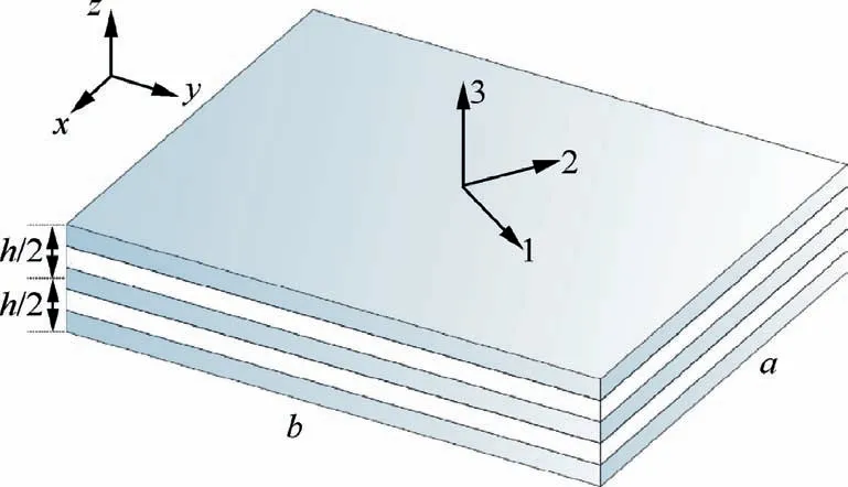
Fig. 1 A multi-layered plate structure.
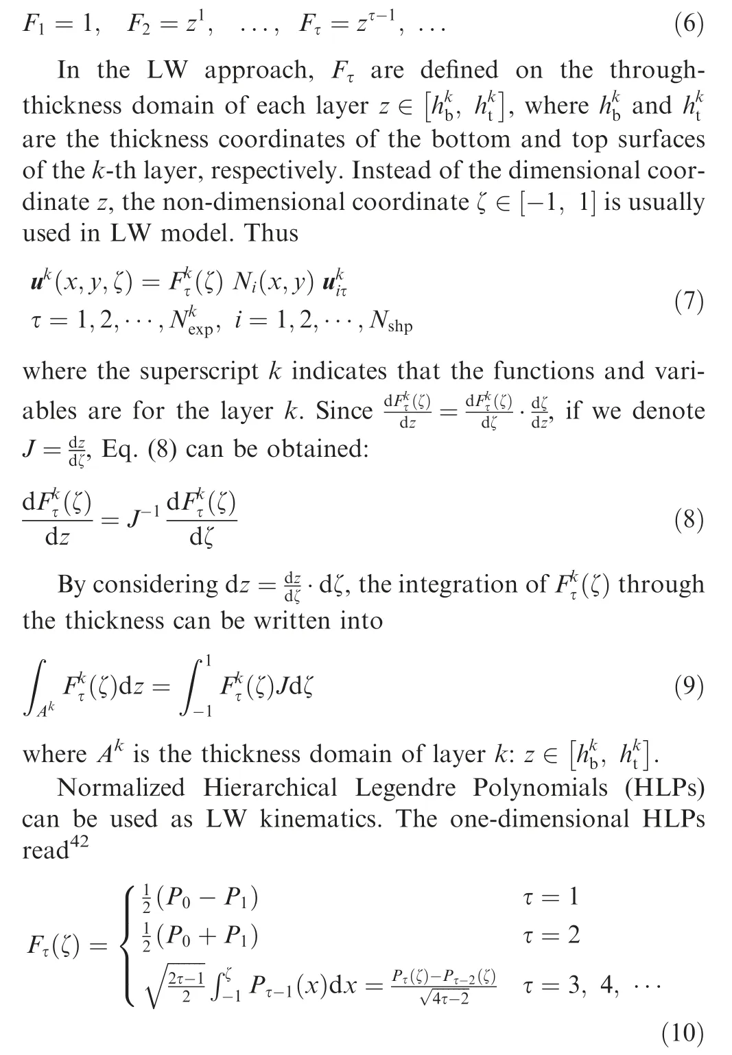
where Pτis the Legendre polynomial, which possess the characteristics of orthogonality and hierarchy.
The p-version two-dimensional shape functions42are also constructed utilizing the HLP as in Eq.(10).Such hierarchical shape functions are classified into node modes, edge modes,and surface modes, as detailed by Szabo´ et al.42
3.2. Node-Dependent Kinematics (NDK)
The NDK is derived from CUF. By relating the definition of the thickness functions to the specific FE nodes, local kinematic refinement can be implemented.The shape functions will naturally blend the dissimilar kinematics coexisting in an element. Such an NDK element can be used to construct a kinematic transition zone, which bridges elements with refined kinematic to those with simpler assumptions, as discussed by Zappino et al.35,43and Li et al.36

For a plate element with NDK, the displacement field can be written into Eq. (11), plate elements with mixed ESL and LW nodal capabilities can be constructed.
Piezoelectric components are often local structural features,for the modeling of which refined LW kinematics are needed.The NDK technique is ideal for simulating such structures since it provides modeling convenience and accuracy at controlled computational expenses. As shown in Fig.2, the shape functions of the elements in the patched region use LW kinematics, and the rest of the shape functions can adopt ESL assumptions to save the computational consumption. Note that the sectional definitions(patched or un-patched)are properties of the elements.This feature enables one to conveniently explore a great variety of patch configurations (such as placement, in-plane shape, and thickness) with one set of mesh grids. The optimal patch layout can improve the performance of the structure regarding actuation efficiency or vibration frequencies.
In hierarchical plate elements, the higher-order shape functions do not have actual nodes.In this case,the kinematic definitions will be dependent on shape functions that share the same mode featuring position (on a node, an edge, or the surface), as discussed by Zappino et al.43and Li et al.36
3.3. Variational statement and FNs
In this section, the equilibrium equations of the elements are derived utilizing the PVD, and the expressions of the stiffness matrices and load vectors are presented.
For a unit volume dV in the k-th layer, one has

where V is the volume;Γ is the external surfaces;¯p is the vector of the external traction; ¯Dnis the surface charge per unit area;dΓ is a unit area on an external surface.Only surface loads are considered in the present work. In static cases, the inertial effect is discarded.
The FE approximations of the displacements and electric potential and their corresponding virtual variations are
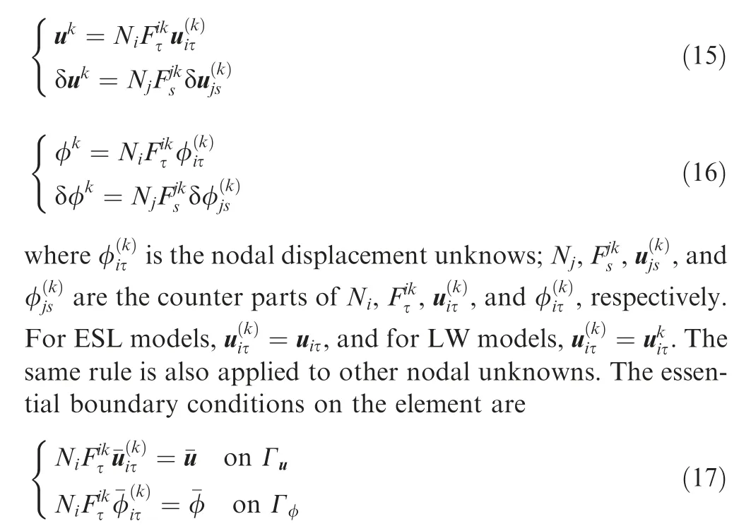
where Γuand Γφare the boundaries for the enforced displacements and electric potential, respectively.
By considering the above FE approximations Eqs. (15)–(17), the geometrical relations Eq. (1), the gradient equations Eq. (3), and the constitutive relations Eq. (4), Eq. (12) can be written as
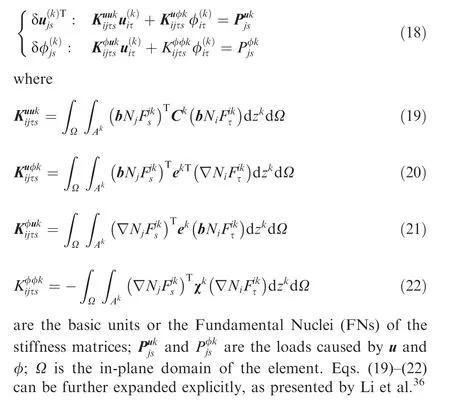
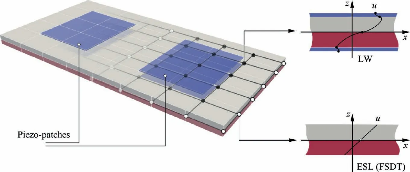
Fig. 2 A composite plate with surface-mounted piezo-patches simulated with NDK.
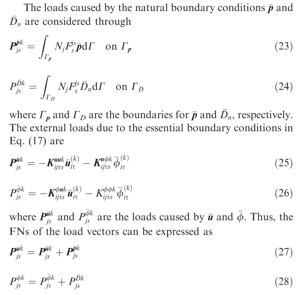
Note that the loads are usually imposed onto different external boundaries of the element.
By looping over the indexes i, j, τ, and s, the element stiffness matrices and load vectors can be obtained in the CUF assembly procedure for NDK FE models, which has been detailed by Li.41
3.4. Adaptive mathematical refinement capabilities
Through mathematical refinements on the shape functions and thickness functions, accurate numerical solutions can be obtained without modifying the FE mesh. The polynomial order of the hierarchical shape functions can be gradually increased, and then the kinematic assumptions in the critical regions can be refined step by step until a numerical convergence is reached. The desired accuracy determines the levels of the mathematical refinements.A group of selected variables(displacements, stresses, and/or electric potentials) at a set of inspection points can be used to monitor the convergence of the solution.The relative difference Δ of a variable Q between two successive rounds of simulation is

where M and M-1 indicate the current and previous rounds of simulations, respectively. The average of a group of relative differences Δican be denoted by ¯δ. If δ is the prescribed convergence threshold, a refinement procedure stops when ¯δ ≤δ.Once the refinement on the shape functions terminates, the local enrichment of the thickness functions in the critical zone starts.
4. Numerical examples
In this section,three numerical examples are studied.First,the numerical accuracy of the presented FE models is assessed through the Heyliger’s plate benchmark. Second, a two-ply composite plate with two configurations of surface-mounted piezo-patches is investigated. Next, the presented NDK FE approach is applied to optimize the piezo-patch layout through the Genetic Algorithm (GA) to improve actuation efficiency.
4.1. Heyliger’s plates
A two-ply square laminated plate with PZT-4 piezoelectric layers bonded to the top and bottom surfaces is studied.The lamination of the plate is(90°/0°)(from bottom to top).The length and width of the plate are a=b=4 m, and thickness h=1 m. The thickness of each piezoelectric layer is 0.1 h,and each elastic layer is as thick as 0.4 h. Material properties of the composite lamina and PZT-4 are listed in Table 1 and Table 2,respectively.Both actuating and sensing cases are considered. The analytical solutions were provided by Heyliger.44
In both the actuator and sensor cases, the square plate is supported on the four edges, which means that the following boundary conditions are applied:
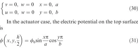
where φ0is the reference electric potential, φ0=1 V. The boundary conditions for the electric potential are φ=0 at
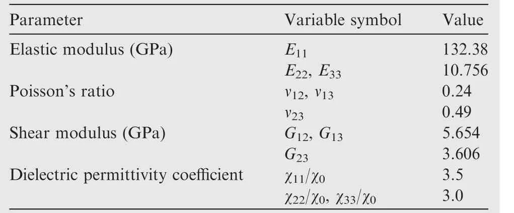
Table 1 Material properties of composite lamina used on two-layered square plate.
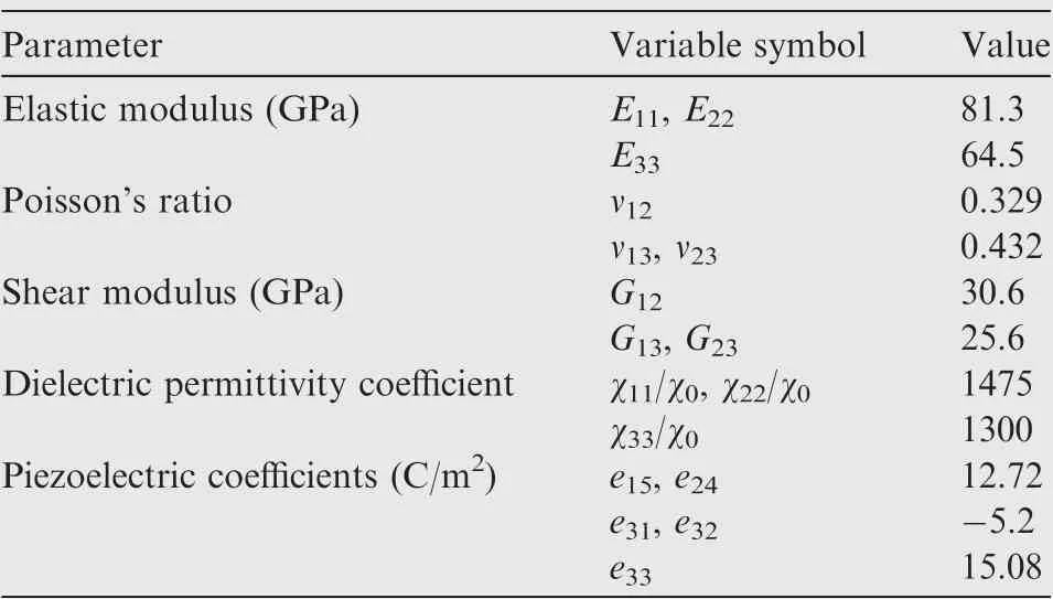
Table 2 Material properties of PZT-4.
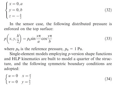
When the piezoelectric layers are used as actuators, the approach through Linear Least Squares (LLS) is adopted to enforce the distributed electric potential as in Eq. (31). This LLS approach had been used to introduce distributed temperature onto hierarchical elements by Li et al.45The FE models are first enhanced by increasing the plate elements’ order and then refined using higher-order kinematic assumptions. The LW kinematic assumptions adopt the HLP, and are denoted by LDn,where n is the order of the thickness functions in each layer. The letter ‘‘D” indicates that the formulations are derived through PVD, and only displacement variables are considered as primary variables besides the electric potential.
The numerical convergence is monitored by checking the average relative difference ¯δ of a set of variables obtained in two successive simulations. For comparison purpose, an FE model employing brick element C3D20RE (a piezoelectric 20-node solid with reduced integration) in ABAQUS is built.This solid FE model consists of 40×40×28 (x×y×z) elements. Due to the limitation of the aspect ratio of solid elements, the in-plane mesh of thin layers needs to be highly refined, leading to a large number of DOFs. Plate elements do not have such limitations. The p-version elements support the mathematical enrichment of the shape functions,and thus,re-meshing can be avoided. Besides, the NDK technique enables the elements to possess mixed ESL/LW kinematic capabilities, which can further improve the numerical efficiency.
The obtained numerical solutions are summarized in Table 3 and Table 4. By comparing the solutions to Dzgiven by p9-LD1 and p9-LD2 in Table 4, it can be concluded that a linear through-the-thickness assumption of the electric potential φ leads to results far from accuracy since Dzdepends on the gradients of φ. From Table 3 and Table 4, it can be observed that the numerical convergence is achieved (¯δ ≈0)when the element polynomial degree is 9, and the kinematic refinement reaches LD5. The numerical results show that,for both the actuator and sensor cases, the refined singleelement plate model p9-LD5 can give solutions agreeing well with the references provided by Heyliger44and those obtained through ABAQUS 3D modeling. Exceptionally, in the sensor case, φ obtained with the refined plate model p9-LD5 and ABAQUS is 1/10 of that given by Heyliger.44D’Ottavio and Kro¨plin46and Carrera et al.47obtained the same results as the present solution. Since all the other variables partly depending on φ have been calculated with consistency,this discrepancy was probably caused by the dimensionalization factors46or a printing error.48When the numerical convergence is achieved,the number of DOFs in the refined hierarchical elements is only a small portion of those of the ABAQUS 3D model.
Through-thickness variations of displacements, stresses,and electric variables for the actuator and sensor cases of the two-layered square plate are reported in Fig. 3 and Fig. 4,respectively.The FE solutions obtained through the presented refined plate models and ABAQUS 3D modeling show a good agreement with each other for all the variables. However, as shown in Fig. 3(c), the values of σxxthrough the thickness of the lower piezoelectric layer given by Heyliger44are ten times the present solution. This second discrepancy was also speculated to be a printing error48or brought about by the dimensionalization factors.46
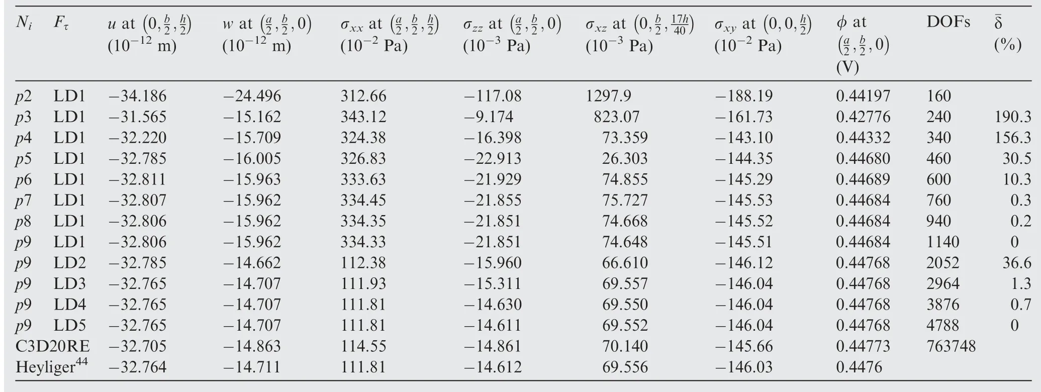
Table 3 Numerical estimation on two-layered square plate with two piezoelectric layers as actuators.
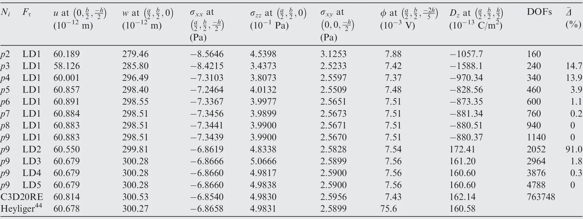
Table 4 Numerical estimation on two-layered square plate with two piezoelectric layers as sensors.
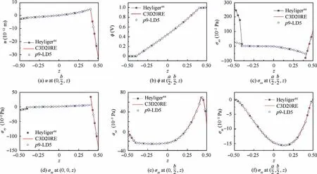
Fig. 3 Through-thickness variations of displacement, electric potential, and stresses on two-layered plate with piezoelectric layers(actuator case).
4.2. Square plates with piezoelectric patches
Piezoelectric actuators are often used to control the shape of structures. In this section, two-layered cross-ply composite square plates with four pairs of surface-mounted PZT-4 piezo-patches are investigated. The plates have length and width a=b=200 mm. The thickness of each orthotropic lamina is 4 mm. The two orthotropic layers have an equal thickness of 4 mm and are laminated in the sequence of(0°/90°). The thickness of each piece of piezo-patch is 1 mm.Two configurations are considered,as shown in Fig.5.In each layout,the total in-plane area of the piezo-patches on each side of the plate is 80 mm×80 mm. The mechanical properties of the composite lamina are the same as in Table 1 without considering the permittivity coefficients. The properties of PZT-4 are given in Table 2.
The plates are simply supported on the four edges as seen in Eq. (30) and imposed to constant pressure load p=100 N⋅m-2on the top surfaces. The piezo-patches are polarized in their thickness directions and are used as extension-mode actuators in the present work. Two types of electric load cases are considered: (A) both sides of the piezo-patches are grounded; (B) the inner sides of the patches are grounded,and the outer sides are imposed to a voltage that can flatten the structure. This example focuses on the application of piezo-patches in the shape control of structures,so only displacements are examined.
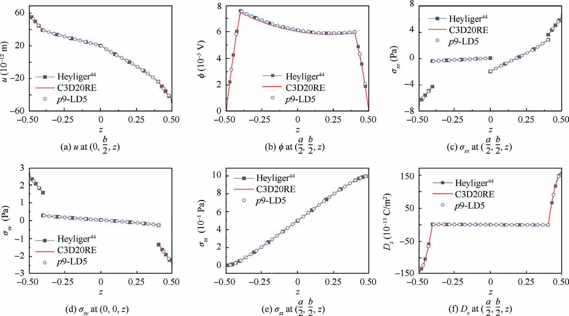
Fig. 4 Through-thickness variations of displacement, stresses, and electric displacement on two-layered plate with piezoelectric layers(sensor case).

Fig. 5 Two-layered composite square plates with piezo-patches.
In the FE model,by making use of the symmetric boundary conditions as in Eq.(34),a quarter of the structure is modeled with 5×5p-version elements. To simulate the patches accurately, LW models are required in the patched region. For the rest of the structure,simpler models,such as ESL assumptions, can save computational costs. The regions with dissimilar types of kinematic assumptions can be connected through NDK elements.As explained by Zappino et al.35and Li et al.,36this kinematic transition zone requires the width of at least one element. In the present work, the elements neighboring the patched region employ LW models to guarantee a proper transition zone,as shown in Fig.5.It can be noticed that,in the FE model for Layout A, more elements are allocated to refined LW kinematics than those for Layout B.
FE models consisting of 3D brick elements are also built on commercial platform ABAQUS. For the composite plate,40×40×4 (x×y×z) C3D20R (a 20-node quadratic brick with reduced integration) elements are used; for the piezopatches, each piece is modeled utilizing 8×8×4 C3D20RE elements. The most significant aspect ratio of the adopted elements is 10. The resultant 3D model is denoted by C3D20R(E), whose numerical results are taken as reference solutions.
The load case(Layout A),which imposes constant pressure on the structure top surface and enforces both sides of the patches to have zero voltage, is first considered. In the FE model with p-version plate elements, the refinement of the kinematic assumptions is first enhanced gradually until Δ ≤1%. Next, the order of the hierarchical elements is increased until the numerical convergence is achieved. This procedure has been demonstrated by Table 5, in which the deflection at the center of the structure(Layout A)is reported.The computational time is reported regarding the dimensionless relative CPU time ¯t with reference to the least refined model p2-LD1,whose¯t=1.0.The relative error e is measured with reference to the results given by the ABAQUS modelC3D20R(E).In Table 5,it can be observed that,e of the result provided by the model p5-LD3 is 0.6%. It should be noted that,from p3 to p4,the significant improvement of the solution accuracy (Δ=13.3%) is mainly brought by the newly introduced surface mode shape function. The readers can refer to Ref. 42 for more details of the hierarchical shape functions.

Table 5 Deflection at center of plate with piezo-patches Layout A under constant pressure and zero electric potential on both sides of piezo-patches.
By means of the same adaptive mathematical refinement procedure, for the composite plate with piezo-patch Layout B, the solutions given by different models are reported in Table 6. Note that TEm indicates that mth-order Taylor expansions (see Eq. (6)) are employed as ESL-type kinematic assumptions for the substrate structure without piezopatches. The NDK model p5-TE1/LD3 leads to a solution with comparable accuracy at a reduced number of DOFs and less CPU time. It can be speculated that if the piezopatches cover a smaller portion of the structure,NDK can further reduce the computational expenses of refined plate FE models.
In load case (Layout B), to control the deformation of the structures, an electric potential ~φ that makes the composite plates flattened is enforced. For Layout A and Layout B, ~φ is 51.4 V and 7.4 V, respectively. The obtained central line deflections along (a/2, y, 0) are reported in Fig. 6. It can be observed that the results provided by the 3D modeling C3D20R(E), the fully refined model p5-LD3, and the NDK FE model p5-TE1/LD3 are in good agreement. The NDK FE model has a distinct advantage over the 3D FE modelingregarding the computational cost (number of DOFs). The results also show that Layout B has higher stiffness and actuation efficiency compared with Layout A.

Table 6 Deflection at center of plates with different piezo-patch layouts under constant pressure and zero electric potential on both sides of piezo-patches.
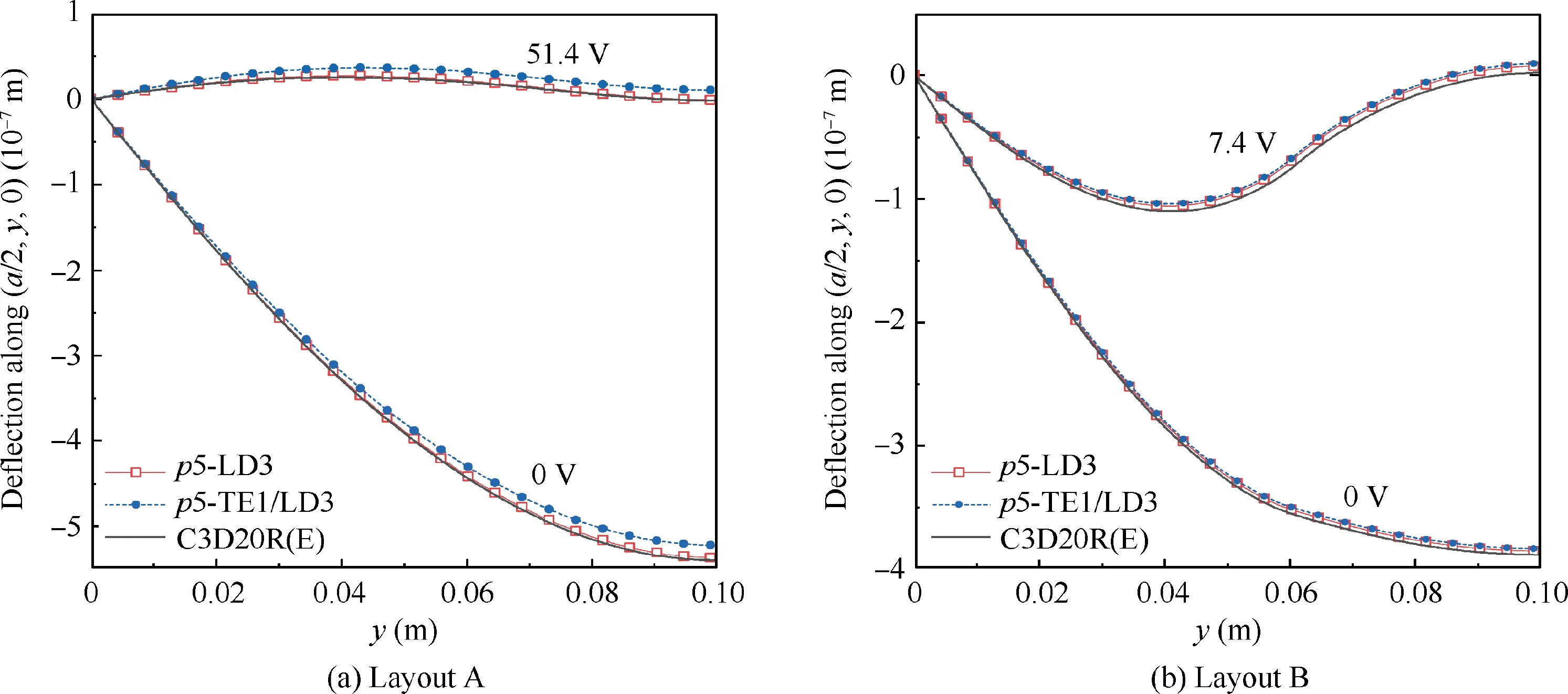
Fig. 6 Central-line deflections of composite square plates with two types of piezo-patch layouts under constant pressure and electric potential.
4.3. Optimization of piezo-patch layout on two-layered square plate
The placement of the piezo-patches on composite structures is explored through the GA. The substrate structure is the twolayered composite plate in Section 4.2. The optimization aims to find the optimal layout of four pairs of square piezo-patches that provides the highest possible actuation efficiency. The plate is simply supported on its four edges. The patches’ inner surfaces are grounded, and the outer sides have been enforced with the voltage of 100 V. The piezo-patches are used as extension-mode actuators.
A patched composite plate needs to be encoded into a bitstring chromosome to be used in the GA.The two types of sections, namely patched and un-patched, are represented by the Genes 1 and 0,respectively. Thus, a string of the genes results in a chromosome representing a structure with a specific patch layout.Fig. 7 demonstrates the GA encoding and decoding of the problem. The quality of a design is evaluated through the fitness, which is the deflection at the central point of the composite plate in the present work,and the FE simulation will act as the fitness function. By means of selection, crossover, and mutation, the samples gradually evolve generation by generation based on a randomly generated initial population. For more information about the GA, the readers can refer to the work of McCall.49
But instead of sleeping he only lay awake and thought of the hermit s prophecy; and the more he thought of it the angrier he felt, until he gnashed his teeth and declared that it should never, never come true
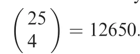
We postulate that the optimal layout has symmetric features. Thus, a quarter of the structure is simulated. The FE models adopt the NDK plate elements used in Section 4.2.The NDK model p4-TE1/LD1 is adopted to generate the structural response since it is computationally cheap and provides results with fair accuracy.Since the FE model consists of 25 plate elements, the string length of the chromosome is 25.Each piece of piezo-patch is approximated by four elements with the patched sectional features. The un-patched region is modeled with elements employing section definition with only composite laminae.In the optimization,the crossover possibility pc=0.8 and the mutation possibility pm=0.1. The population size is chosen to be 25, and two rounds of optimization have been conducted.
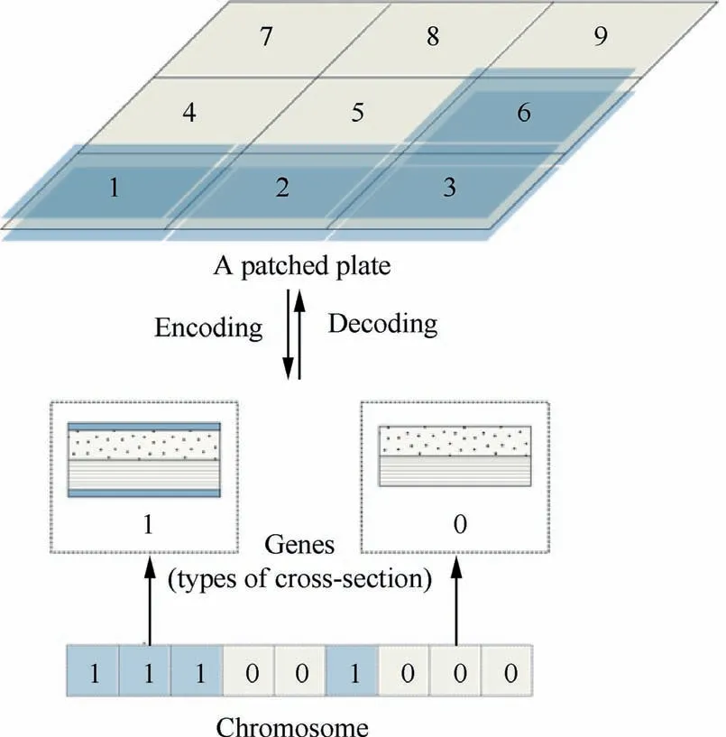
Fig. 7 Chromosome encoding and decoding of a patched plate structure.
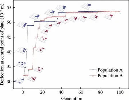
Fig. 8 Evolution of piezo-patch layout on composite plates.
Fig. 8 shows the deflection of the most efficient sample in each generation.It can be observed that,within 60–80 generations,the two populations gradually evolved and converged to the optimal solution,which has four pairs of patches clustered in the central region of the structure.This solution is consistent with the results in Fig. 6 in Section 4.2. This result is theoretically reasonable since, for such a structure under simple support, the bending deformation mainly occurs in the central region. A single large piece of patch provides higher bending stiffness than multiple distributed patches when used as surface-mounted actuators.
(1) The structural configuration is conveniently encoded in the GA since the sectional feature is defined as a property of the plate elements.
(2) The modeling of all the samples can use the same set of mesh grids. Thus, the re-meshing is avoided, and an automation process can be conveniently conducted.
(3) The numerical efficiency is guaranteed using the hierarchical elements with mixed ESL/LW kinematics.
Once the optimal configuration is decided, the same mesh grids can be immediately used in the detailed simulation thanks to the capabilities of the hierarchical elements and variable kinematics.This example shows that the NDK FE models can be conveniently used in the optimization of patched composite structures.
5. Conclusions
(1) The use of hierarchical shape functions and variable kinematics makes it convenient to efficiently refine the FE models to achieve high numerical accuracy without re-meshing.
(2) Through NDK, the region with piezoelectric components can be modeled in the Layer-Wise(LW)approach,and the un-patched composite substrate can be approximated through simple Equivalent Single-Layer (ESL)models.
(3) With an appropriate kinematic transition, the NDK technique can help improve the numerical efficiency by achieving comparable numerical accuracy as full LW modeling at reduced computational expenses.
(4) Using NDK,smart structures with various patch configurations can be conveniently simulated and explored with one set of mesh grids.
(5) The suggested NDK FE approach is promising to be used in the optimization of structures with piezoelectric components.
The present work has been focused on static analyses. The proposed approach can be applied to vibration control problems as future work.
Declaration of Competing Interest
The authors declare that they have no known competing financial interests or personal relationships that could have appeared to influence the work reported in this paper.
Acknowledgements
This research has been carried out within the project FULLCOMP (Fully analysis, design, manufacturing, and health monitoring of Composite structures),funded by the European Union Horizon 2020 Research and Innovation Program under the Marie Sklodowska Curie Grant Agreement (No. 642121).E. Carrera and G.M. Kulikov acknowledge the Russian Science Foundation (No. 18-19-00092). Y. Hou acknowledges the financial support from National Natural Science Foundation of China (No. 52005451).
 CHINESE JOURNAL OF AERONAUTICS2021年8期
- CHINESE JOURNAL OF AERONAUTICS的其它文章
- A novel virtual material layer model for predicting natural frequencies of composite bolted joints
- Modeling bending behavior of shape memory alloy wire-reinforced composites: Semi-analytical model and finite element analysis
- Sequential ensemble optimization based on general surrogate model prediction variance and its application on engine acceleration schedule design
- Transition prediction and sensitivity analysis for a natural laminar flow wing glove flight experiment
- Modeling on mechanical behavior and damage evolution of single-lap bolted composite interference-fit joints under thermal effects
- Experimental and numerical simulation of bird-strike performance of lattice-material-infilled curved plate
