Modeling on mechanical behavior and damage evolution of single-lap bolted composite interference-fit joints under thermal effects
Junshan HU, Kaifu ZHANG, Hui CHENG, Peng ZOU
a College of Mechanical and Electrical Engineering, Nanjing University of Aeronautics and Astronautics, Nanjing 210016, China
b School of Mechanical Engineering, Northwestern Polytechnical University, Xi’an 710072, China
c Aircraft Strength Research Institute of China, Xi’an 710065, China
KEYWORDS Composite joints;Damage evolution;Interference fit;Mechanical behavior;Thermal effects
Abstract This paper reports the modeling method and outcomes of mechanical performance and damage evolution of single-lap bolted composite interference-fit joints under extreme temperatures.The anisotropic continuum damage model involving thermal effects is established on continuum damage mechanics which integrates the shear nonlinearity constitutive relations characterized by Romberg-Osgood equation.The temperature-induced modification of thermal strains and material properties is incorporated in stress-strain analysis, extended 3D failure criteria and exponential damage evolution rules. The proposed model is calibrated and employed to simulate behavior of composite joints in interference fitting,bolt preloading,thermal and bearing loading processes,during which the influence of interference-fit sizes, preload levels, laminate layups and service temperatures is thoroughly investigated. The predicated interfacial behavior, bearing response and failure modes are in good agreement with experimental tests. The numerical model is even capable of reflecting some non-intuitive experimental findings such as residual stress relaxation and matrix softening at elevated temperatures.
1. Introduction
Carbon fiber reinforced polymer (CFRP) composites are increasingly employed to fabricate primary load-bearing structures in aerospace industry owning to their high strength,light weight and good fatigue resistance over conventional materials.1,2Despite that good designability of composites can reduce the number of components and improve structural integrity,the decision to use assembly structures instead of single ones is driven by fabrication,functionality and maintenance.3These composite components are connected by mechanical fasteners,4,5among which the bolted interference-fit joints have been revealed to improve load bearing and fatigue performance by introducing residual stresses around joint-holes in assembly6and alleviating oscillatory stress amplitude in service.7However,the joints often induce stress concentration and fiber discontinuities which make them the weakest parts in the whole structures,8and the interference fit even causes damage to composites.9Furthermore, the composite joints are often exposed to extreme environments in service condition. The thermal loading not only causes unmatched thermal swelling and contraction between components10but also alters the material properties of composites,11which would cause premature failure of joint structures. Therefore, an in-depth knowledge about the mechanical performance of composite interference-fit joints under thermal effects is exceedingly crucial for structural design and application.
The performance of composites and their joint structures under thermal conditions have been experimentally studied for years considering the fact that the matrix resin is sensitive to service temperatures.The mechanical behavior of composite laminates at extremely low and elevated temperatures were investigated by Sa´nchez-Sa´ez et al.12and Vieille et al.13,14respectively.The results show that the stiffness of the laminates grew as the temperature decreased,while high temperature contributed to enhancing the ductile behavior of the matrix resin as well as degrading the fiber/matrix interface. The properties of glass/epoxy composite before and after mechanical loading and hygrothermal conditioning was examined by Abdel-Magid et al.15who found out that extended exposure to moisture and load at room temperature would result in catastrophic failure,while higher temperature might lead to ductile failure of continuously laminated glass/epoxy composites.
As for composite joint structures, the simplest pin-loaded bearing tests under various temperatures were performed by Hirano el al.16It turned out that the bearing failure occurred due to various damages caused by environmental temperature.The bearing behavior of bolted composite joints at low and elevated temperatures were evaluated by Soykok et al.17,18It revealed that joints exhibited relatively higher load-carrying capability when temperature decreased, and tightening torque was effective even at elevated temperature and contributed to joint strength. Song et al.19conducted the experimental study on the failure strength of carbon/epoxy single lap riveted joints after thermal exposure and observed an approximately 23–25% reduction in failure load which was attributed to heat damage to the matrix.The fatigue bearing failure of composite bolted joints under biaxial loading at elevated temperature was investigated by Kapidzˇic´ et al.20,21It revealed that the biaxial loading yielded a longer fatigue life than the uniaxial loading for the same maximum peak resultant force.
Although the mechanical behaviors of composites and their joint structures under thermal effects can be obtained by massive experiments, it is burdensome to conduct enormous expensive and time-consuming tests because of the diversity of composite materials and complex testing environments.Therefore, the need for reliable and efficient numerical approach on failure prediction of composite joints is highly imperative for structural design and analysis. Actually many numerical and analytical methods have been developed to model the response and failure of different composite structures.The fully transient hygrothermal stress in polymer composite plates was analyzed by Benkhedda et al.22via a microto-micro mechanical model where the material properties were considered to be dependent on temperature and moisture. A progressive failure analysis model involving hygrothermal effects was proposed by Zhang et al.23to predict the failure of notched composite plates. The nonlinear bending behavior of a three-dimensional braided composite cylindrical panel under transverse loads was investigated by Zhao et al.24using a micro-macro-mechanical model.When it comes to modeling of composite joints,the specimen configuration,25stress distribution,26assembly process27and loading behavior28in roomtemperature conditions were intensively studied via finite element (FE) models, which provided intuitional information of the basic performance of composite joints. Based on the similar FE framework,A pin-loaded FE model which incorporated temperature-dependent material properties was developed by Goswami29to predict bearing failure load. Santiuste et al.30introduced the Hashin failure criteria to evaluate the stress fields and damage regions in bolted composite joints under thermal effects. Furtherly, Zhang and Rowland31employed the mixed failure criteria together with Tan-Camanho and Chang-Tserpes material degradation rules to investigate the damage evolution in composite joints under mechanicalthermal loading. These modeling behaviors and failure analyses at temperature extremes are practical design approaches because they can provide extra visual angle that would be difficult to observe experimentally.
To the authors’best knowledge,most of the above numerical simulations concerning thermal effects are main focused on the intact composites and their joint structures such as clearance-fit pinned or double-lap bolted joints,it is still lack of relative investigation on the service performance of composite interference-fit single-lap bolted joints where the residual stress and initial damage induced in assembly process would evaluate and propagate under extreme thermal conditions.Moreover,the alternation of properties of composite laminates under different service temperatures would tangle with the constantly evolving stress and damage states,which adds complexity to the numerical modeling and causes convergence problems.
These facts and problems have motivated the authors to focus on the current research, which involves a systemic modeling on mechanical behavior and damage evolution of singlelap bolted composite interference-fit joints under extreme temperatures. The temperature-induced modification of thermal strains and material properties is incorporated in the constitutive model and applied in the extended three-dimensional(3D)failure criteria as well as exponential damage evolution rules.Particular attention is paid to the interfacial behavior,bearing response, damage evolution and failure modes under mechanical-thermal coupling effects. Corresponding experiments have been carried out to verify the proposed model. It is hoped that the modeling method reported herein will provide some guidance for design and application of such joints in service.
2. Continuum damage model involving thermal effects
2.1. Nonlinear constitutive relations concerning thermal effects
Fiber-reinforced polymer composites are easily affected by thermal loadings.5Temperature variation causes distinct changes in size and shape in three material principle directions of composites due to their anisotropy. Commonly the stress–strain relationship can be obtained by combining the thermal strains with the stress-included strains:

where σ and ε are actual stress and strain components in composites,respectively. C is material stiffness matrix. Parameters α are the temperature expansion coefficients.ΔT is the temperature increment.
The unidirectional composites are transversely isotropic and the temperature would not induce shear strains in composites. Thus the normal stress–strain relation involving thermal effect is defined by:

in which normal expansion coefficients satisfy the relationship α2= α3.
Although the temperature doesn’t induce shear strains, the shear stress–strain relation of composites shows obvious nonlinear response, especially with softened matrix under thermal loading.5Herein the shear stress–strain relationship in Eq. (1)can be replaced by Romberg-Osgood formulation:32
where G0is initial shear modulus, τmdenotes the shear stress when shear strain γ approaches to infinity, and n is the fitting parameter of the shear stress-strain curve. It should be noted that γdequals to γ before damage initiation.Once failure in relevant shear plane occurs,γdwill remain stable.All of the three shear components follow the nonlinear relation in Eq. (3) on assumption that the single ply of the composite laminates is transversely isotropic.

2.2. Material degradation due to thermal effects
The alteration of the temperature in composites not only causes normal thermal strains,but also changes the mechanical properties of composites.10The non-dimensional temperature T*proposed by Tsai33is the essential parameter for evaluation of the composite thermal characteristics and can be defined as:

where Tgand T0are the glass transition temperature and room temperature, respectively. Parameter T denotes the service temperature.
Then the exponents of T*is used to empirically fit the composite lamina stiffness and strength as functions of the service temperature.The elastic modulus under different thermal conditions can be estimated as:22

where E1,E2,E3,G12,G13and G23are the basic material properties of composite materials.Their variants with superscript T represent the properties under thermal effects at temperature T. Parameters a and b are power-law indexes determined by composite materials.
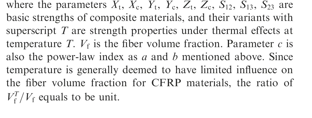
Additionally, the temperature also has significant effect on the strength of composites.23The relation between the temperature and strength are as follows:

2.3.Damage initiation and propagation involving thermal effects
Due to thermal effects,the stiffness matrix of composite in Eq.(1) exhibits temperature-dependent feature:

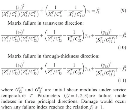
Similarly, when taking into account of the thermal effects on the failure analysis of composites structures, the constitution relation appending the 2D strain-based failure criteria proposed by Linda34are modified into 3D formulation concerning thermal effects as follows:
Fiber failure in longitudinal direction:
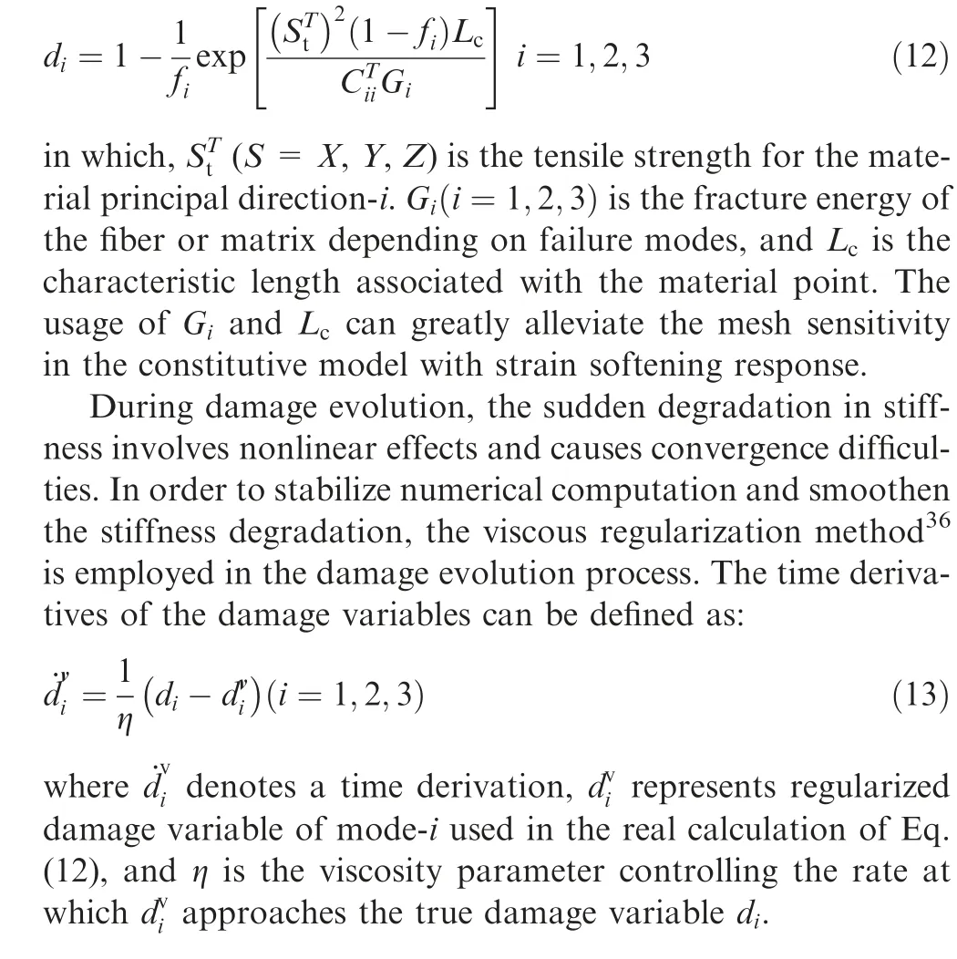
If failure is detected in a material point, damage initiates and propagates with the increasing load. To characterize the damage growth, the exponential damage evolution law adopted for each damage variable is expressed in the following form:35
2.4. Damaged material response
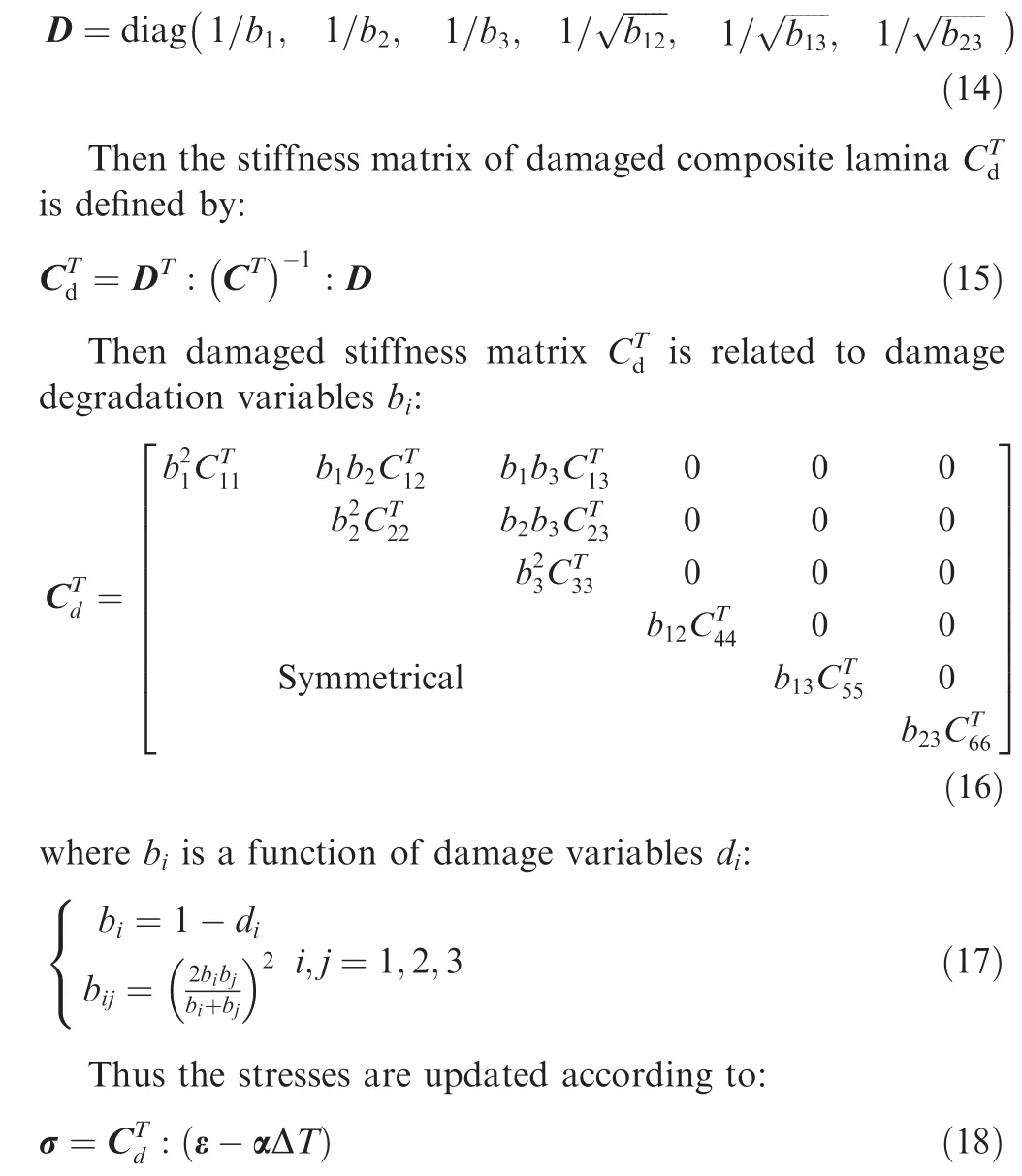
In order to describe the effect of damage on material stiffness,the second-order diagonal tensor D proposed by Matzenmiller37is introduced into the damage model and can be defined with the damage degradation variables bi:
By differentiating the Eq. (18), the Jacobian matrix can be formulated as follows:

where Δt is the time increment.Based on the above continuum damage algorithm, a user defined subroutine UMAT which contains the aforementioned failure criterion and material degradation under thermal effects is developed, and the flowchart of the proposed method is depicted in Fig.1.Thus a nonlinear continuum failure analysis of composites as well as their joint structures can be implemented under thermal conditions.
3. Model calibration and experimental validation
3.1. Material properties and model calibration
The composite laminates manufactured by Guangwei Composites Co. Ltd. were employed to validate the proposed continuum damage model. The unidirectional carbon fiber prepreg USN20000 with a thickness of 0.2 mm per ply was used as reinforcement and unsaturated polyester resin 7901 was used as matrix. The glass transition temperature Tgof the matrix in employed laminates was about 110°C.38The mechanical properties of the lamina are presented in Table 1,where the asterisked parameters are set according the transverse isotropy assumption.
In order to calibrate the shape parameter n and maximum shear stress τmof Romberg-Osgood equation in the proposed material constitutive model, an experimental test using an 8-ply [±45]2slay-up specimen with a dimension of 250 mm×25 mm×1.6 mm was prepared according to ASTM D3518 Standard39as illustrated in Fig. 2, where two strain gauges were pasted centrally in a right angle with each other to capture the strain εxand εyin X and Y directions, respectively. The shear stress–strain relationship was fitted by Eq.(3) and presented in Fig. 3. Through curve fitting, the parameter n is 3.12, and τmequals to 107.1 MPa.
Apart from the shear response, the initial failure stress and strain in fiber and matrix directions under thermal effects were also evaluated at the element scale to validate the proposed continuum damage model. The exponent indexes a, b and c in Eq. (7) were set to be 0.04, 0.25 and 0.2, respectively.23The Stress-strain curves from single-element FE models compared with corresponding experiments are presented in Fig.4.The results show that the proposed numerical approach predicts the fiber and matrix response accurately, and that both the initial failure stress and strain in matrix direction are more severely affected by the service temperature than those in fiber direction.
3.2. Modeling of composite interference-fit joints concerning thermal effects

Fig. 1 Algorithm of continuum damage model under thermal effects.

Table 1 Mechanical properties of composite lamina.

Fig. 2 Test configurations for shear nonlinearity calibration(unit: mm).
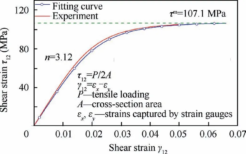
Fig. 3 Parameter calibration of nonlinear shear response in Romberg-Osgood equation.
The single-lap bolted composite interference-fit joints subjected to the combination of tensile and thermal loading were modeled as a complex case. The joint configuration was illustrated in Fig.5,where the ratios of the width(w)and the edge distance(e)to the bolt diameter(d)were w/d=6 and e/d=3 respectively to ensure bearing failure according to ASTM D5961 Standard.40Three typical composite lay-ups, namely quasi-isotropic (QI, [90/±45/0]2s), angle-ply (AP, [±45]4s)and cross-ply (CP, [0/90]4s) laminates, were employed as the top and bottom coupons in the joints.Joints were secured with 6 mm diameter Ti-alloy aerospace grade fasteners (protruding head bolts and nuts). The material properties of fasteners are presented in Table 2. The influences of three different interference-fit sizes (0.5%, 1.2% and 2.1%), three levels of tightening torques (10, 4500, and 9000 N) and four levels of service temperatures(-25,25,75,110°C)on joint performance were investigated.
The 3D FE model of composite joint is established to perform bearing behavior and damage evolution concerning thermal effects.For the sake of clarity,only half-symmetric part of the model with boundary conditions is presented in Fig. 6. In the numerical joint model, the bolt, nut and washer were merged into a dumbbell-shaped component to reduce contacting surfaces and shorten computing time.Each ply of the laminate coupons was modeled by a single layer of C3D8R elements with enhanced hourglass control. The mesh of the joint-hole region was highly refined with an element size of 0.19×0.20×0.20 mm. The nodes at the end of the bottom coupon were fixed in X, Y, Z and their rotating directions.The uniformed displacements was applied at the end of the top coupon in X direction. The friction coefficient values for laminate-to-laminate (SC1), bolt head-to-laminate (SC4 and SC5), bolt shank-to-laminate interfaces (SC2 and SC3) were 0.5,0.2 and 0.1,respectively,based on the previous studies.28,38The three desired interference-fit sizes between bolt-shank and joint-hole were realized via interference-fit options in ABAQUS platform. The nut-side preloads of 10, 4500 and 9000 N were exerted on the bolt-load plane using bolt load option to replicate the three torque conditions.As for the thermal effects, the volumetric changes of joint components were reflected by their thermal expansion coefficients set in material behavior option and the environmental temperature in predefined filed option respectively, whereas the material properties degradation of composites caused by mechanical-thermal coupling loading and damage evolution was achieved by the proposed continuum damage model implemented in UMAT subroutine.

Fig. 4 Validation and prediction of stress–strain response.
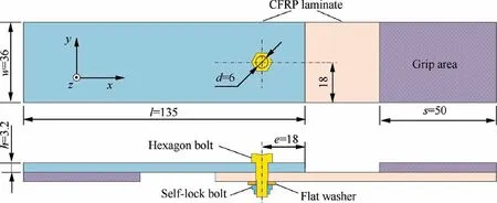
Fig. 5 Geometry and dimensions of composite single-lap, single-bolt joint configuration (unit: mm).

Table 2 Mechanical properties of Ti-alloy fasteners.
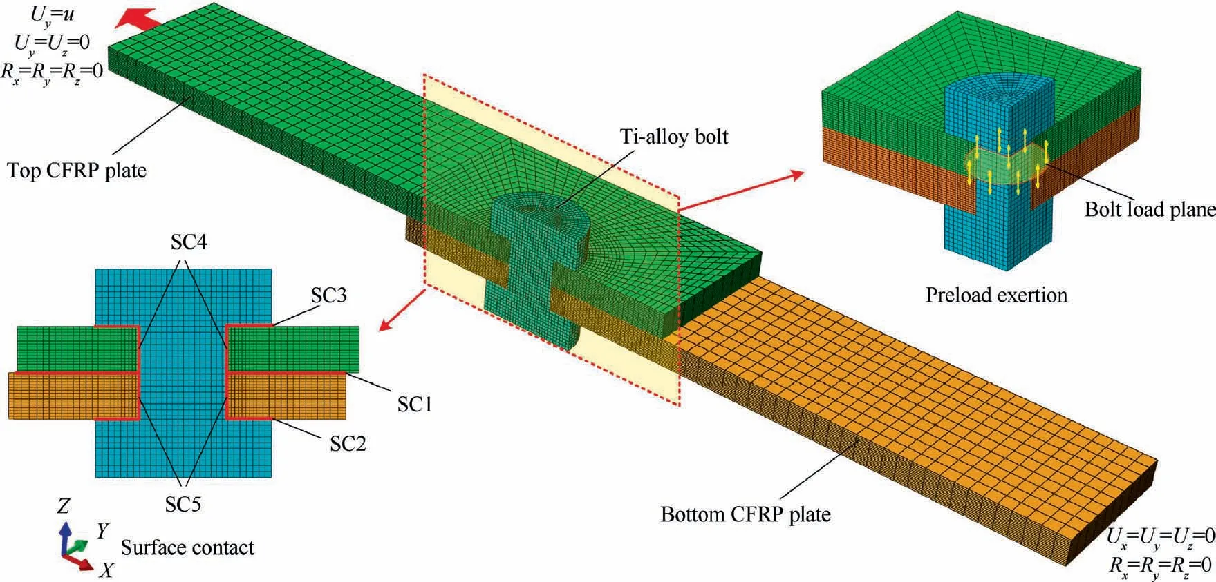
Fig. 6 3D FE model of single-lap bolted composite interference-fit joints.
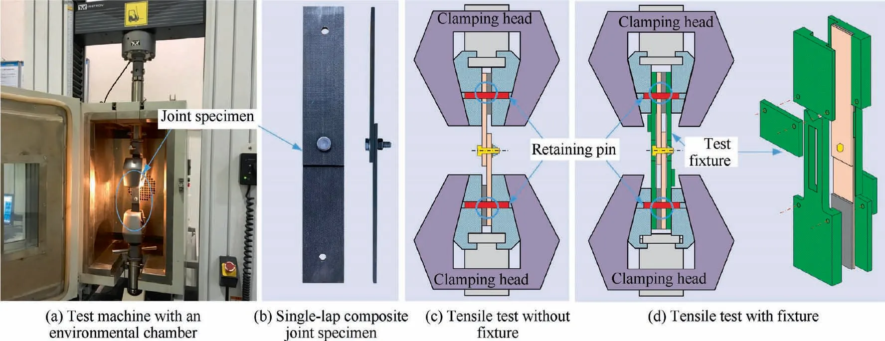
Fig. 7 Tensile test of composite interference-fit joints in universal testing machine with a temperature chamber.
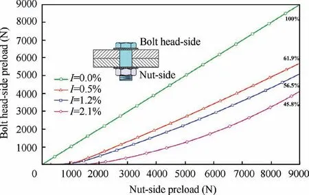
Fig. 8 Preload variation of composite joints with four levels of interference-fit sizes.
After the establishment of the 3D FE model and the boundary conditions of composite joints, four calculating steps were built for its numerical modeling. Firstly, the specific interference fit between bolt-shank and joint-hole was formed in the joint at room temperature. Then the nut-side preload was exerted on the bolt-load plane to clamp the lapped composite coupons tightly. Thirdly, the thermal load was applied to the joint model to cause volume change of joint components and material properties degradation of composite specimens. At last, the uniaxial displacement was applied to the joint model together with the successive thermal load from the third step.The above four steps were in corresponding to the bolt installing, screw tightening, thermal and displacement loading,which covers the entire assembly and usage conditions. The programmed UMAT subroutine was called to evaluate the damage initiation and evolution in composite joint model.The simulation procedure stopped as soon as either target displacement load was reached or the computation failed to converge prematurely.Besides,in order to validate the superiority of the proposed nonlinear model,the linear constitutive model proposed by Linda et al.34was also employed to simulate the bearing response of composite single-lap joints for comparison.
3.3. Tensile test of composite joints under thermal effects
In order to validate the proposed numerical simulation of composite interference-fit joints under thermal effects, the same joint configurations with the numerical models as depicted in Fig. 5 were prepared for experimental tests.
Before testing,the composite coupons with QI,AP and CP layups were cut by water-jet dissector to ensure their accurate geometry sizes. The designed joint-holes (5.970, 5.929,5.877 mm in diameter) in composite coupons were achieved by customized tools with integrated drilling and reaming functions. Then the aerospace grade Ti-alloy bolts (a standardized diameter of 6.0 mm) were pressed into the undersized jointholes by an electronic universal testing machine (Bairoe,WDW-10)at a rate of 3 mm/min to form the designed interference fit size of 0.5%,1.2% and 2.1%, after which the Ti-alloy nuts were screwed to fasten composite coupons by a torque wrench to obtain desired torque levels (0.5, 6, and 12 Nm).Each joint configuration was prepared with three specimens.
The quasi-static tensile tests of composite interference-fit joints under thermal effects were performed using a universal testing machine (INSTRON 3382 with a load capability of 100 kN) with an environmental chamber as illustrated in Fig. 7(a). The chamber was equipped with liquid nitrogen cooler and heating apparatus to create different service temperatures of -25, 25, 75 and 110°C. For setting the temperature to a fixed value, the chamber was isolated to obtain a stable temperature. An adjustable thermostat was mounted inside it to control heating and cooling process. Before tensile tests, the joint specimens were placed in the chamber for 15 minutes to reach the temperature balance. In order to avoid sliding in grip area when matrix was softened at elevated temperature, both ends of the joint specimen was pinned into the clamping chunk as illustrated in Fig.7(c).The tensile tests were conducted in the chamber with 2 mm/min ramp speed, during which the applied tensile load vs displacement of machine stroke was recorded. Each joint configuration was repeated three times.
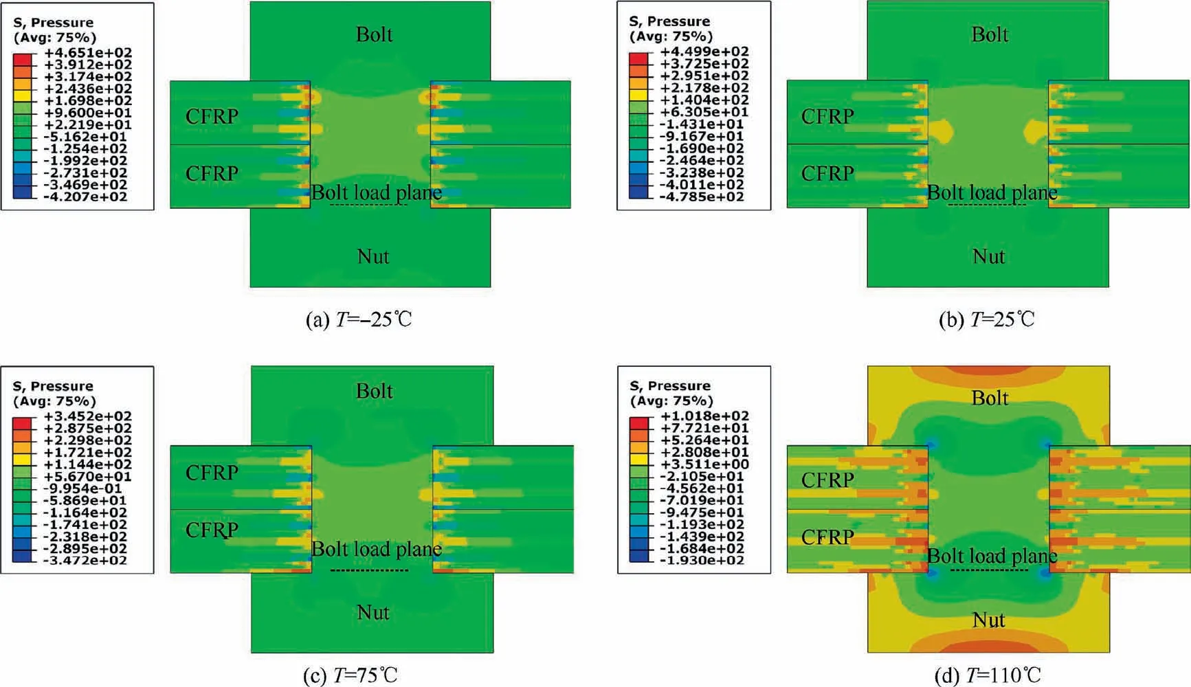
Fig. 9 Interface pressures distribution in composite interference-fit joints with an interference-fit size of 1.2% and a preload of 4500 N under thermal effects.
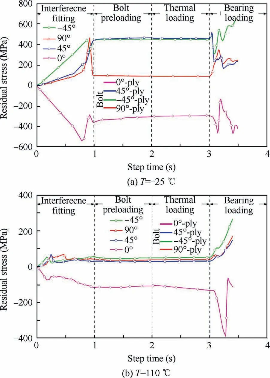
Fig.10 Residual stress evolution in composite joint model of QI layup with an interference-fit size of 1.2%and a preload of 4500 N under extreme temperatures.
Since the previous researches revealed that the eccentric loading path in such single-lap joints would cause excessive bolt inclination10and the subsequent premature failure of joint-holes41which could not be numerically modeled because of bad convergence, the tensile tests with fixture according to ASTM D5961 Standard40were conducted to validate the bearing behavior of the FE model as shown in Fig.7(d).The fixture just helped to prevent bolts from excessively punching into laminates and would not restrict out-of-plane deformation.
After the test,the joint specimens were cut near the bearing plane. The exposed bearing interfaces under various service temperatures were inspected by scanning electron microscope(SEM). Besides, the fiber and matrix damages in the bearing regions were also captured by X-ray technique.
4. Results and discussion
4.1. Interfacial behavior in composite interference-fit joints
In the numerical model of composite interference-fit joint, the initial preload is applied to the joint through the bolt-load plane, and the relations between the nut-side and bolt headside preloads under different interference-fit sizes are presented in Fig. 8. Due to the interfacial friction between bolt-shank and joint-hole, a part of the preload is counterbalanced by the frictional force on the interference interface. Thus there is a difference between nut-side and bolt head-side preloads.The final proportions of preload at the bolt head-side to the initial preload or preload at the nut-side for interference-fit size of 0%, 0.5%, 1.2% and 2.1% are 100%, 61.9%, 56.5% and 45.8% respectively, indicating that the frictional force grows with the increase of interference-fit size.It should be noted that in the case with high interference-fit size, the preload at bolt head-side responses nonlinearly to the exerted preload at nut-side, which explains that the preloading process furtherly aggravates the damage in the joint-hole interface. Consequently, the interfacial residual stress degrades and the level of frictional force is reduced.The degree of interfacial damage and response nonlinearity exacerbates with the increase of interference-fit size,which coincides with the trends in pervious experimental reports.10
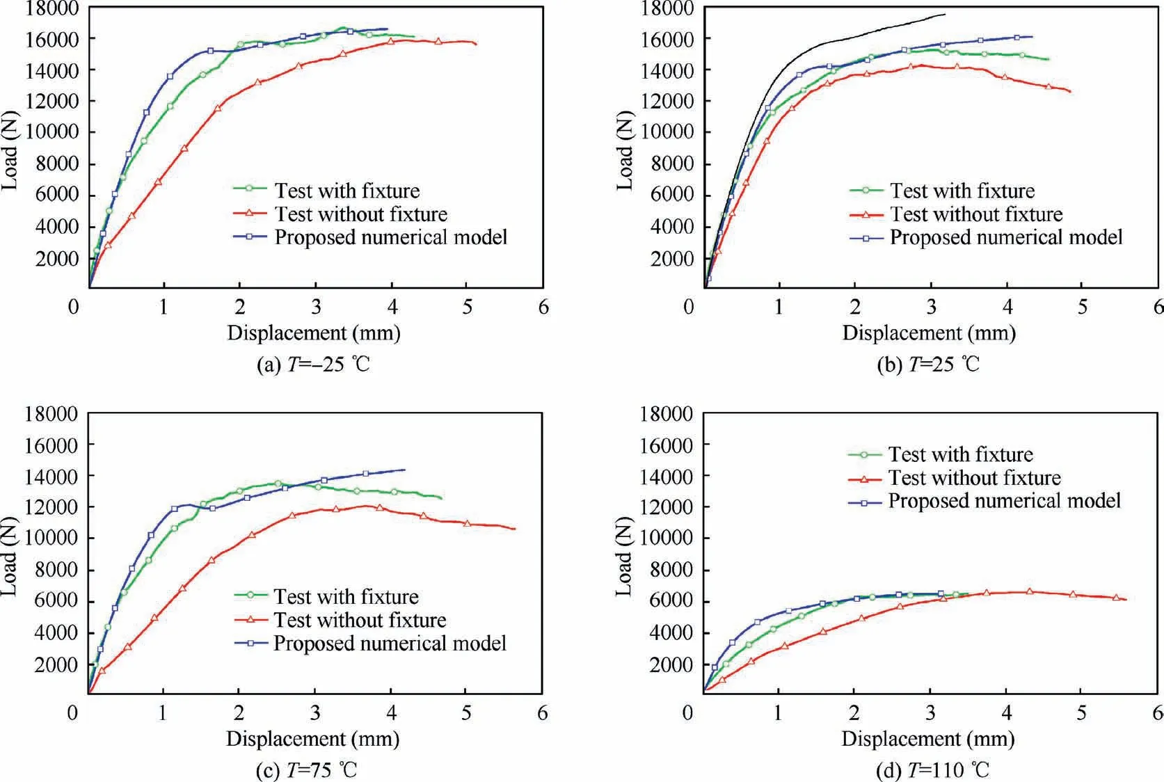
Fig.11 Validation of proposed numerical model via tensile tests of composite joints with an interference-fit size of 1.2%and a preload of 4500 N under thermal effects.
The thermal effects on interfacial pressure between bolt shank and joint-hole in numerical model of composite interference-fit joint with an interference fit size of 1.2% and a preload of 4500 N are presented in Fig. 9. At the ambient temperature of 25°C (Fig. 9(b)), since the preload at nutside is apparently greater than that at bolt head-side,the pressure concentration mainly occurs on the nut support area of the bottom laminate. The maximum pressure reaches 449.9 MPa, which exceeds the matrix strength. Thus there is matrix damage in the contacting interface which have been observed in pervious literature41. When the temperature falls to -25°C (Fig. 9(a)), the preload is reduced due to the cold contractions of joint components. The stress concentration occurs at the interference interface between bolt-shank and joint-hole since the fibers are barely affected by the low temperature.Owning to the inconstant shrink of joint components and cold hardening of matrix in composite laminates,the maximum pressure increases to 465.2 MPa. As the temperature rises to 75°C (Fig. 9(c)), although joint components present thermal expansion,the thermal softening of matrix in composite laminates is the dominant factor that results in a lower maximum pressure, about 345.2 MPa, at the nut support area of the laminate. The predominant feature of matrix softening is even enhanced as it approaches to glass transition temperature of 110°C (Fig. 9(d)). The discrepancy of interlaminar deformation brings about comb-shape distribution of interfacial pressure. The matrix resin nearly converts to rubbery state which loses the bond and support ability for fibers. The residual stress is relaxed and the maximum pressure decreases to 101.8 MPa.
With the purpose of comprehensively understanding the interfacial behavior, the residual stresses at the bearing side of joint-holes in top 0°, 45°, -45° and 90° plies are investigated. Since there is not much difference among stress state at-25,25 and 75°C as depicted in Fig.9,only stress evolution under extreme temperatures of -25 and 110°C is elaborately compared in Fig. 10. It can be observed that the stress evolution can be divided into four processes,namely interference fitting, bolt preloading, thermal loading and bearing loading.Due to the interference-fit feature, the joint-hole is radially compressed and circumferentially expanded. Regardless of temperature, the 0°-plies exhibit negative stress state since the fiber bundles bear much of the load in radial direction,whereas the matrix in other three plies present positive stress state because of the circumferential extension.
At low temperature of -25°C in interference fitting process, the stress in 0°-ply first increases linearly to a maximum value of 542 MPa, then it decreases to 296 MPa due to fiber damage induced by interference-fit formation. The±45°-plies approach to a secondary maximum stress of 517 MPa.The 90°-ply reaches to 463 MPa and drops off to 87 MPa owning to matrix damage.These residual stresses remain relatively stable in bolt preloading and slightly decline because of cold contraction in thermal loading. Finally, the residual stresses of the four typical plies exhibit dramatic fluctuations by virtue of the severe damages as illustrated in Fig. 15(a) in bearing loading process.
At high temperature of 110°C, since the matrix is highly softened, the composite laminates nearly lose the ability to bear external load. The residual stresses induced by interference-fit formation is relaxed and reduced to a low level,especially for±45°and 90°piles whose material properties are matrix-dominant. The thermal expansion contributes to the slight growth of residual stresses but the effect is limited. In bearing loading process, the stresses increase sharply due to the squeezing of inclined bolt-shank as depicted in Fig. 15(d), but the stress level is much smaller than that at cold temperature of-25°C,indicating that the bearing load capability is seriously weakened.
4.2. Bearing response of composite interference-fit joints
Through the proposed continuum damage model, the load bearing response at the structural scale of composite interference-fit joints under thermal effects are evaluated in Fig. 11, where the tensile tests with and without specimen fixtures are implemented for modeling validation.
Generally,the load–displacement curves in all cases present three typical stages, the elastic linear stage, the damaged nonlinear stage and the post-failure stage.At all temperatures,the bearing response in load–displacement curves from the test with fixtures are well characterized by the proposed numerical model in the elastic linear and early nonlinear stages. Then there is an apparent deviation in the late nonlinear stage between them, and it trends to exasperate as the temperature rises. This deviation mainly caused by the specific geometry or structure of the clamping jaws as depicted in Fig. 7(c). As the top clamping head move upward to exert tensile load to the joint specimen, the two clamping jaws continue to tighten the grips areas. This makes the inner parts of the jaws move towards to each other and brings an extra displacement recorded in the machine stroke. As a result, the tensile load is of the experimental test at a specific displacement is smaller than that of from the numerical simulation. With the increase of temperature, the elastic linear stage is shortened and the damaged nonlinear stage elongates due to matrix softening in composites. This phenomenon is the most obvious in Fig. 11(d) when it approaches to glass transition temperature of 110°C. Finally, the numerical method accurately captures the fluctuation of the response in the post-failure stage.It also can be observed in Fig.11(b)that the proposed nonlinear continuum damage model captures the nonlinear behavior and the post-failure phenomenon much better than Linda’s linear model at room temperature of 25°C, whereas the latter overestimates the joint stiffness and bearing strength of composite single-lap joints. In view of this, the comparison between two models at low or elevated temperatures is omitted.
However,the curves from the test without fixture only correlate with the numerical curve in early elastic linear stage in all temperature cases. After that they present substantial deviation between each other. Similar results are observed in the previous research which points out that the deviation originates from the absence of washers and excessive bolt inclination.41Without washers distributing the load to the laminates around joint-holes, such hexagon bolt-heads with sharp corners punch into the laminates easily under eccentric loading, causing premature failure to joint-holes as illustrated in Fig. 15.
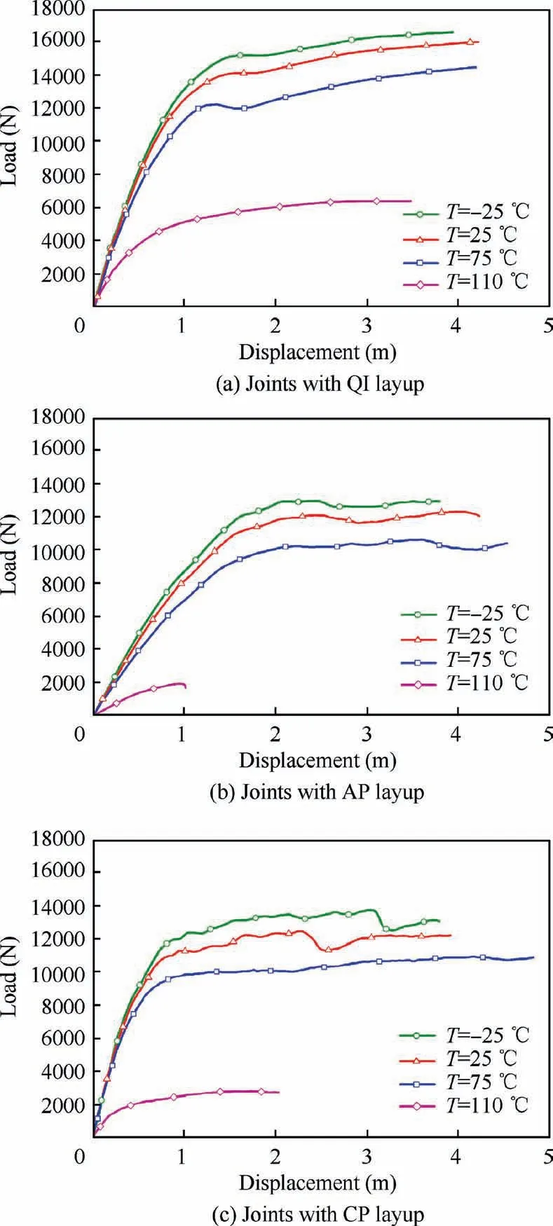
Fig. 12 Bearing response of composite joints with an interference-fit size of 1.2% and a preload of 4500 N under thermal effects.
In view of its validation and accuracy in bearing response of composite joints, the proposed numerical method is used to investigate the thermal effects on composite joints with QI,AP, CP laminate layups. The joints are set with the same interference-fit size of 1.2% and nut-side preload of 4500 N.The predicted load–displacement curves are presented in Fig. 12.
In all the joint models under 75°C, the load-displacement curves exhibit the aforementioned three typical stages regardless of composite layups. As displacement load is gradually applied to the joint model,the slopes of these curves first keep constant,then gradually decline up to zero at inflection points which are corresponding to the initial bearing strengths. For joints with each composite layup, the nonlinear stage of the curves comes much earlier and the slopes at this stage decrease slowly with the increase of temperature. The difference is that at each temperature, the joint with QI layup presents higher loading capability than that with AP and CP layups. At glass transition temperature of 110°C,since the matrix in composite is highly softened, the joint structures exhibit severe nonlinear bearing response and the bearing capability is seriously undermined.The most obvious case is in Fig.12(c), where the loaddisplacement curve of joint with AP layup presents a sharp drop-off after a short nonlinear stage,indicating the premature failure of the joint structures.
The joint stiffness and bearing strength abstracted from composite interference-fit joint models with QI, AP and CP layups under four levels of temperatures are presented in Fig. 13, where test joint specimens is also exhibited for comparison. It can be observed that both the joint stiffness and bearing strength in all joint cases decrease steadily with the increase of temperature before 75°C, and this tendency is accelerated when matrix resin is gradually softened near the glass transition temperature 110°C.Thus the whole curves display an exponential decline. In terms of joint with QI layup,the joint stiffness points from numerical models are within the standard devaluation band of experimental results at all temperatures except those near 110°C owning to the conservative deformation of FE models, whereas the joint strength of the former fall exactly in the deviation band of the latter,demonstrating the accuracy of the numerical method. When it comes to composite layup, the stiffness of joint with CP layup is the highest at moderate temperature levels, followed closely by the joint with QI layup and then AP layup.But there is an exception at 110°C where the stiffness of the joint with CP layup falls below the joint with QI layup, indicating that the latter layup displays better stiffness retention even under high temperatures(Fig.13(a)).Besides,the joint with QI layup also demonstrates much greater initial bearing strength at any temperature levels, whereas the strength of joint with AP and CP layups are roughly the same. Hence it can be concluded that the bearing response of composite joints is highly dependent on layups and architectures of laminates.42
4.3. Damage evolution and failure mode of composite joints
In addition to load bearing response, the damage evolution and failure mode in numerical models of composite interference-fit joints under thermal effects are compared with the experimental observations attained by X-ray technique to validate the accuracy of the proposed modeling method. The in-plane damage features of top composite coupons in joints with QI layup under various temperature environments are presented in Fig. 14.
In all the cases of-25,25 and 75°C which are far below the glass transition temperature of 110°C, the damages are localized in the square connecting region as illustrated in Fig.14(a)to (c). Apartment from the minor damages scattered around the joint-hole created by the interference fit formation, the major fiber (SDV1 in Fig. 14(a1) to (c1)) and in-plane matrix damages(SDV2 in Fig.14(a2)to(c2))caused by the squeezing of the bolt-shank at the bearing side are in accordance with the damaged whitening zones detected in the X-ray images(Fig.14(a) to (c)). The crescent through-thickness matrix damages at the tensile side (SDV3 in Fig. 14(a3) to (c3)) are induced by the indentation of inclined bolt-head or nut which are also observed in Fig. 15. Since the degree of matrix softening is intensified by the ascending temperature,the damaged regions extend to the free side of the composite coupons and joint-hole elongates greatly along the tensile direction in both numerical and experimental results.
As the temperature reaches 110°C, the matrix resin is totally softened. The loading capability of composite joints decreases sharply as reflected by Fig.11(d).The damages propagate from the joint-hole edge to the side-edges in composite coupon along the 0° and ±45° directions, taking on Y-shape bands in X-ray image (Fig. 14(d)), and such special damage bands are accurately simulated by the numerical joint model in the form of fiber failure accompanied by matrix damage(Fig. 14(d1) and (d2)). Since the softened matrix in laminate coupons loses the resistance to the preload in throughthickness direction,the matrix resin on the surface of the laminates is crushed by the bolt-head or nut as illustrated in Fig. 14(d3), revealing that the through-thickness properties of laminates is severely attenuated.
Composite single-lap joints always exhibit out-of-plane deformations due to the eccentric load path,which is generally known as secondary bending7. This bending effect induces complicated stress distribution around joint-holes which then results in non-uniformed damage features in throughthickness direction. In order to understand the throughthickness failure mechanism in composite joints under thermal effects, the tested joint specimens with QI layup are dissected through bearing plane and the microstructures are captured by optical microscope as illustrated in Fig. 15 for modeling verification.

Fig. 13 Stiffness and strength of composite joints with an interference-fit size of 1.2% and a preload of 4500 N under thermal effects.
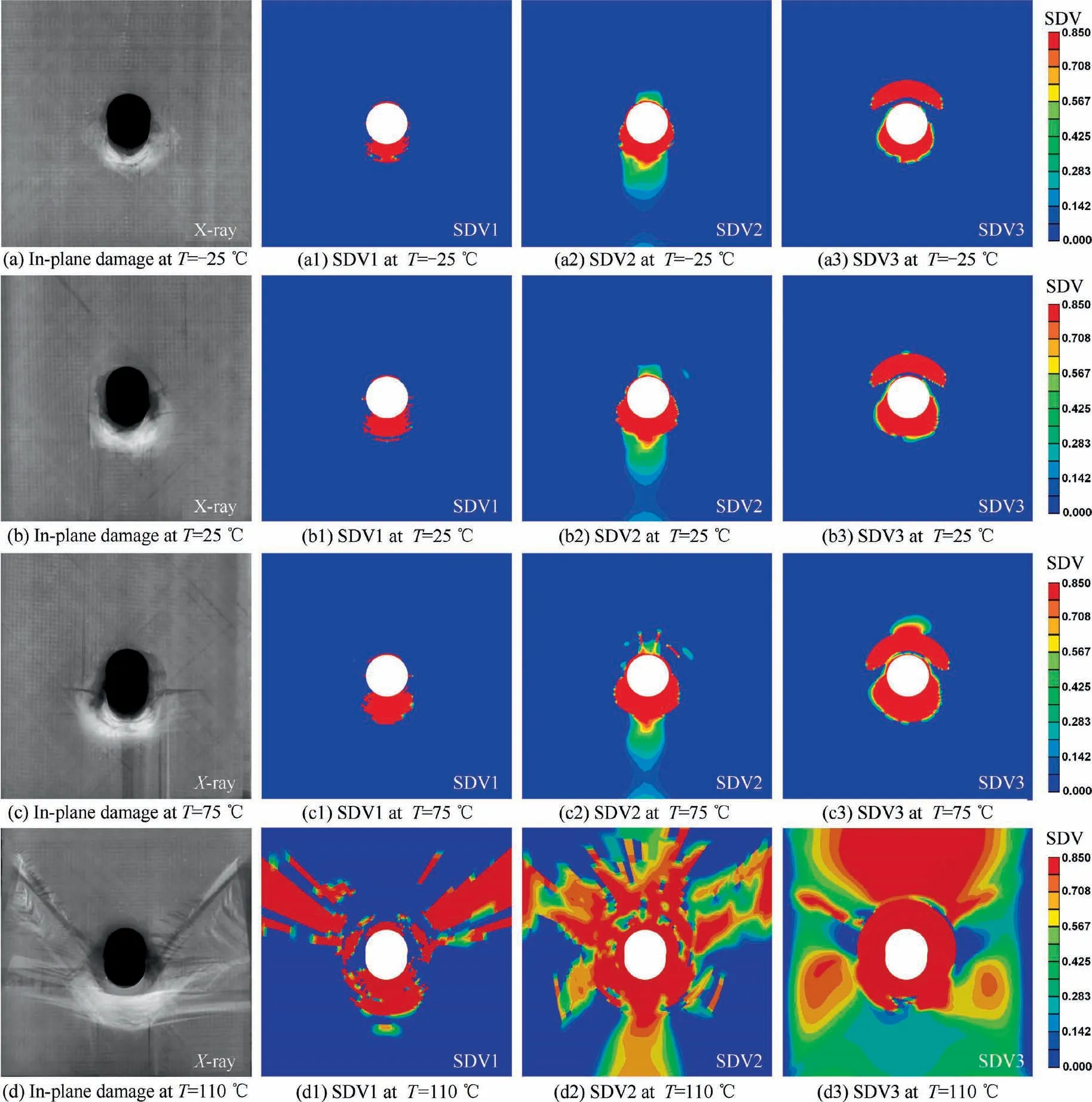
Fig. 14 In-plane damage evolution of composite interference-fit joints with QI layups under thermal effects.
At room temperature of 25°C (Fig. 15(b)), there is apparent relative movement between the top and bottom composite coupons under the eccentric tensile load, which makes the joint-hole at the tensile side move away from the bolt and leaves a void between them. The bolt-shank presents an inclination of 13.8°and squeezes the joint-hole at the bearing side.Severe fiber fracture, matrix cracking and delamination are observed in the bearing plane.These damages are well characterized by the numerical joint model in Fig. 15(b1) to (b3),where the areas and modes of fiber failure(SDV1),matrix failure in plane (SDV2) and through thickness (SDV3) coincide with the damage occurs in the tested joint specimens.The only difference is that the simplified cylindrical bolt-head in the numerical model only cause an indentation on the composite coupon, whereas the hexagon bolt-head punches into the top composite coupon at the tensile side and cuts off part of the joint-hole into pieces in the experimental test.
At low temperature of -25°C (Fig. 15(a)), since the cold environment makes the joint components shrink, the preload exerted to the fastener is reduced. The interfacial friction between two composite coupons is attenuated and the relative movement between them is greater than that at room temperature.Thus the bolt-shank inclines with a larger angle of 16.0°.Besides, the low temperature also hardens the matrix in composites and makes the laminate exhibit strong brittleness.The damage on the bearing plane is less severe than that at room temperature. This change can also be reflected by the reduced fiber and matrix damage areas in Fig. 15(a1) and(a2). The more severe bolt inclination is also captured in numerical joint model, which then creates deeper indentation on the composite coupon and induces more serious matrix damage to the laminate as illustrated in Fig. 15(a3).
At moderate temperature of 75°C, the angle of the bolt inclination grows to 24.2°. This growth is a mixed effect of thermal expansion of joint components and matrix softening in composites. That is, the thermal expansion of components intends to induce higher level of preload in joints and stronger interfacial friction between composite coupons, whereas the matrix softening plays the predominant role in decreasing the preload and reducing joint stiffness.Consequently,the lateral support for 0°-plies is weakened and layer buckling is observed at the bearing side of the joint-hole in Fig.15(c).Similarly,such damages are predicted in the form of bucks of damaged elements with corresponding failure modes (fiber layer bucking, matrix plasticity and crushing) as in plane and through thickness(Fig.15(c1)to(c3))in the numerical model.Although the temperature is elevated, the damages are still localized around the joint-hole in both experimental and numerical morphologies.
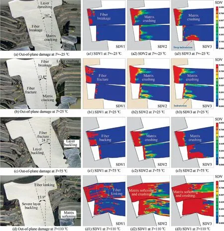
Fig. 15 Out-of-plane damage evolution of composite interference-fit joints with QI layups under thermal effects.
As it rises to the glass transition temperature of 110°C,the matrix transforms from glass state to rubber state and loses the function to bond and support fiber bundles.Severe fiber buckling or kinking and matrix plasticity are observed at the bearing side in Fig. 15(d). In the numerical model, fiber failure mainly occurs in the same region under the bolt-head or the nut at the bearing side(Fig.15(d1)),whereas the matrix failure spreads to the whole composite laminates as illustrated in Fig. 15(d2) and (d3). Since the matrix is totally softened and the composite lose the ability to resist the bearing load, the bolt inclination is reduced to 13.9°. These serious damages in composite joints suggest that the operating temperature range of composite laminates should be far below the glass transition temperature of 110°C.
5. Conclusion
In order to investigate the performance of composite interference-fit joints under extreme temperatures,an anisotropic progressive damage model concerning thermal effects is proposed based on continuum damage mechanics.The properties of composites are considered temperature-dependent and incorporated in stress–strain analysis, extended 3D failure criteria and exponential damage evolution rules. A user defined subroutine is developed and implemented in ABAQUS platform to conduct the numerical simulation where the interfacial, bearing response and damage evolution are elaborately analyzed and validated by experiments. The following conclusions can be obtained:
(1) The proposed numerical method which integrates nonlinear shear constitutive relation and temperaturedependent modification of thermal strains and material properties predicts the mechanical response and failure mechanism of composite single-lap bolted interferencefit joints at extreme temperatures with high fidelity and robust computation. The stress evolution, component deformation and damage regions are well characterized by the numerical joint model.
(2) The numerical joint model reflects the nonlinear preload loss along bolt axis from nut-side to bolt head-side caused by interfacial friction between bolt-shank and joint-hole. The loss severity and nonlinearity aggravates with the increase of interference-fit size.The influence of thermal swelling and contraction of joint components on residual stresses is limited,but elevated temperature near Tg. alters initial interfacial state and causes residual stress relaxation by softening matrix resin in composites.
(3) The bearing response is slightly strengthened by the low temperature and gradually undermined by the elevated temperature, but it is sharply weakened near Tgwhere the matrix in composite laminates is highly softened and the joint almost loses the resistance to external load.Thus the joint stiffness and bearing strength presents an exponential decline with the increase of interference-fit size.The joint with QI layup possesses the best retention capability under thermal effects.(4) Both the in-plane and out-of-plane bearing damages are localized at low temperature.The damage region slightly extends with the increase of temperature but propagates to the edge of joint specimen when it reaches Tg. The fiber fracture or breakage and matrix crushing caused by bolt inclined are observed experimentally and characterized numerically at low and moderate temperature,then they switch to fiber buckling or kinking and matrix plasticity at high temperature.
Declaration of Competing Interest
The authors declare that they have no known competing financial interests or personal relationships that could have appeared to influence the work reported in this paper.
Acknowledgements
The work reported herein is finically supported by Joint Found for Equipment Advance Research and Aerospace Science and Technology of China(No.6141B061401)and Fund for Distinguished Young Scholars in Shaanxi Province of China (No.2018-JC-009).
 CHINESE JOURNAL OF AERONAUTICS2021年8期
- CHINESE JOURNAL OF AERONAUTICS的其它文章
- A novel virtual material layer model for predicting natural frequencies of composite bolted joints
- Multi-layered plate finite element models with node-dependent kinematics for smart structures with piezoelectric components
- Modeling bending behavior of shape memory alloy wire-reinforced composites: Semi-analytical model and finite element analysis
- Sequential ensemble optimization based on general surrogate model prediction variance and its application on engine acceleration schedule design
- Transition prediction and sensitivity analysis for a natural laminar flow wing glove flight experiment
- Experimental and numerical simulation of bird-strike performance of lattice-material-infilled curved plate
