Multiscale modeling of mechanical behavior and failure mechanism of 3D angle-interlock woven aluminum composites subjected to warp/weft directional tension loading
Zhenjun WANG, Siyun YANG,b, Shiping SUN, Yingfeng ZHANG,c,Chngchun CAI, Bowen XIONG,*, Wei YANG, Zhifeng XU, Hun YU
a School of Aeronautical Manufacturing Engineering, Nanchang Hangkong University, Nanchang 330063, China
b Hunan Aviation Powerplant Research Institute, Aero Engine Corporation of China, Zhuzhou 412002, China
c School of Mechanical Engineering, Northwestern Polytechnical University, Xi’an 710072, China
KEYWORDS Aluminum matrix composites;Failure mechanism;Mechanical behavior;Progressive damage;Multiscale modeling
Abstract The mechanical behavior and progressive damage mechanism of novel aluminum matrix composites reinforced with 3D angle-interlock woven carbon fibers were investigated using a multiscale modeling approach. The mechanical properties and failure of yarns were evaluated using a microscale model under different loading scenarios.On this basis,a mesoscale model was developed to analyze the tensile behavior and failure mechanism of the composites.The interfacial decohesion,matrix damage, and failure of fibers and yarns were incorporated into the microscopic and mesoscopic models. The stress–strain curves and fracture modes from simulation show good agreement with the experimental curves and fracture morphology. Local interface and matrix damage initiate first under warp directional tension. Thereafter, interfacial failure, weft yarn cracking, and matrix failure occur successively.Axial fracture of warp yarn,which displays a quasi-ductile fracture characteristic,dominates the ultimate composites failure.Under weft directional tension,interfacial failure and warp yarn rupture occur at the early and middle stages. Matrix failure and weft yarn fracture emerge simultaneously at the final stage,leading to the cata-strophic failure of composites.The weft directional strength and fracture strain are lower than the warp directional ones because of the lower weft density and the more serious brittle fracture of weft yarns.
1. Introduction
Continuous fiber-reinforced aluminum matrix composites(CFAMCs)have been extensively investigated in the past several decades due to their excellent properties, such as lightweight,high specific strength and modulus,and fine stability of thermal dimension and thermal aging performance.1–3In addition,good designability in the mentioned thermal and mechanical properties can be achieved through tuning fiber type,fiber volume fraction,and the thermomechanical properties of matrix alloy in the composites.4,5Therefore,they have been regarded as ideal alternative materials to be applied in aircraft and aerospace engineering, such as compressor blades in aeroengines and telescope tubes in reconnaissance satellites.6,7
Considerable numerical research has been conducted in recent years to investigate the failure mechanism and its influence on the mechanical behavior of unidirectional CFAMCs. For example, Tan et al.8investigated the transverse tensile deformation behavior of unidirectional Bf/Al composites by using a unit cell model with homogenous fiber arrangement. The effects of fiber volume fraction,fiber arrangement,and interfacial stiffness on the matrix damage evolution and mechanical response of the composites were parametrically studied, but the inelastic behavior of the interface during deformation was not considered in their micromechanical model. A micromechanical finite element(FE) model for a unidirectional SiCf/Al composite was developed by Chen and Ghosh,9in which a rate-dependent elastoplastic damage criterion and an isotropic failure criterion were used to model the matrix alloy and fiber, respectively. The microscopic damage, stress propagation, and energy absorption and dissipation behavior under dynamic loadings were numerically investigated by assuming perfect interfacial bonding, and the effect of microstructure on mechanical responses was also considered. In Literature,10a unit cell micromechanics model for unidirectional Al2O3/Al composites was constructed, in which the fiber and matrix alloy were assumed to be linear elastic and ideal plastic, respectively. On the basis of the assumption of ideal interface, the plastic deformation behavior of the composites was simulated under off-axis loading and thermal cycling conditions. The dependence of cyclic plastic responses on the fiber cross-sectional geometries was further studied.11A modified cohesive zone model (CZM) was proposed by Xu and Lu.12to consider the inelastic behavior of the interface in a unidirectional SiCf/Al composite. In their studies, the interaction mechanism between matrix plastic damage and interracial decohesion was analyzed, and the failure mode and macroscopic mechanical properties under different property parameters of the interface and matrix alloy were numerically examined.
Most previous research has indicated that CFAMCs possess ultra-high strength and stiffness when loaded at the axial direction of fiber,but the mechanical properties of CFAMCs are relatively poor under the transverse or off-axial loading condition.13–15Consequently, the application of CFAMCs in engineering structures has been limited. To address this issue,different fabric structure CFAMCs have been proposed and developed in recent years. However, the majority of the current literature relevant to fabric structure CFAMCs focuses on the experimental research on their preparation method, microstructure, and mechanical properties. For instance, McWilliams et al.16conducted a numerical simulation on a 2D fabric Al2O3f/Al composite on the basis of a multiscale mechanics framework and found that the specific mechanical behavior of the composite was induced by the damage behavior of the complex fabric structure.The nonlinear effects of the damage and failure of component materials should be considered in predicting the mechanical properties and understanding the failure mechanism of fabric structure CFAMCs.In the past several years,numerous numerical studies have been devoted to investigating the damage and failure mechanism of 3D woven fabric-reinforced polymer matrix composites by using a multiscale modeling approach,and the failure and constitutive models of this type of composites have been well established.17–19To our knowledge, however,research concerning the multiscale modeling of 3D woven fabric-reinforced metal matrix composites is rarely reported.The failure and constitutive models of constituent materials in 3D woven fabric-reinforced aluminum matrix composites,which are different from those in traditional 3D woven fabricreinforced polymer matrix composites, have also not been addressed.
In this work,novel 3D angle-interlock woven carbon fiberreinforced aluminum matrix composites (3DAW-CF/Al composites), as a new type of CFAMCs, were fabricated using the vacuum-assisted pressure infiltration method. The objectives of this work are to characterize the mechanical behavior and to investigate the underlying failure mechanism of this composite under warp and weft directional tensile loads by using multiscale modeling and experimental approaches.First,a microscale model representing the microstructure of yarns and a mesoscale model representing the structure of composites were constructed on the basis of experimental observation.Second, the transversely isotropic elastic constants and strength parameters of yarns were evaluated by conducting a micromechanical simulation based on the microscale model.Third, these mechanical parameters of yarns were implemented to the mesoscale FE model,which was utilized to analyze the mechanics and failure behavior of the composites under warp and weft directional tension. Lastly, the stress–strain curves and fracture behavior from the simulation were examined using the experimental ones, and the damage and failure mechanisms of the composites were discussed in accordance with the simulation and experimental results.
2. Materials and fabrication method
The 3DAW-CF/Al composites used in this study comprised a 3D angle-interlock woven fabric as reinforcement and ZAlMg10 as matrix alloy. The 3D angle-interlock woven fabric was made from graphite fiber M40J provided by Ningbo Institute of Materials Technology and Engineering, Chinese Academy of Sciences. The chemical composition of the ZAlMg10 alloy was 9.5wt%–11.0 wt%Mg, 0.35wt%–0.45wt% Si, 0.05wt%–0.15wt% Cu, 0.15wt% Mn, 0.15wt% Ti,and balance Al; it was provided by Beijing Institute of Aeronautical Materials. The architectural parameters of the 3D angle-interlock woven fabric are listed in Table 1. The total fiber volume inside the 3D fabric was measured through dividing the total fiber weight by the fiber specific gravity.The fiber content in the 3D fabric was obtained through dividing the total fiber volume by the total 3D fabric volume, resulting in the fiber content of 45% in Table 1. The weaving architecture model and actual appearance of the 3D fabric are presented in Fig. 1(a) and (b), respectively.
The 3DAW-CF/Al composites were fabricated using a vacuum-assisted pressure infiltration technology.20The main procedures were as follows. First, the air in the 3D angleinterlock woven fabric was removed using a vacuum pump,and the fabric was heated to a temperature of 560°C. Thereafter, the liquid aluminum alloy with a molten temperature of 720°C was infiltrated into the fabric under the force of argon gas with a pressure of 8 MPa. Lastly, the gas pressure was maintained for 30 min, and the composites were cooled down to room temperature. The appearance of the resulted 3DAW-CF/Al composites is shown in Fig. 1(c).
The dimensions of the specimens for tensile testing are shown in Fig.2(a).The specimens were designed in accordance with ASTM D3552-96,which was adapted to the tensile testing for fiber-reinforced metal matrix composites. Plate specimens were cut from the 3DAW-CF/Al composite plate (Fig. 1(c))along the warp and weft directions. Before tensile testing, the specimens were processed via an artificial ageing treatment at 180°C for 10 h to relieve the residual stress. Pure aluminum sheets with a thickness of 0.5 mm were stuck on the surface of the grip sections of specimens to help prevent abnormal rupture due to the rough grip surfaces, as shown in Fig. 2b.Quasi-static tensile tests were conducted on Instron 5569 at a tensile velocity of 0.5 mm/min. The geometric characteristics and morphological distribution of yarns in the composites were examined using an optical microscope along the warp and weft directions. The microstructure and fracture surface of the composite samples were inspected using SEM Quanta 2000.

Table 1 Architecture parameters of 3D angle-interlock woven fabric.

Fig. 1 3D angle-interlock woven fabric and 3DAW-CF/Al composites.
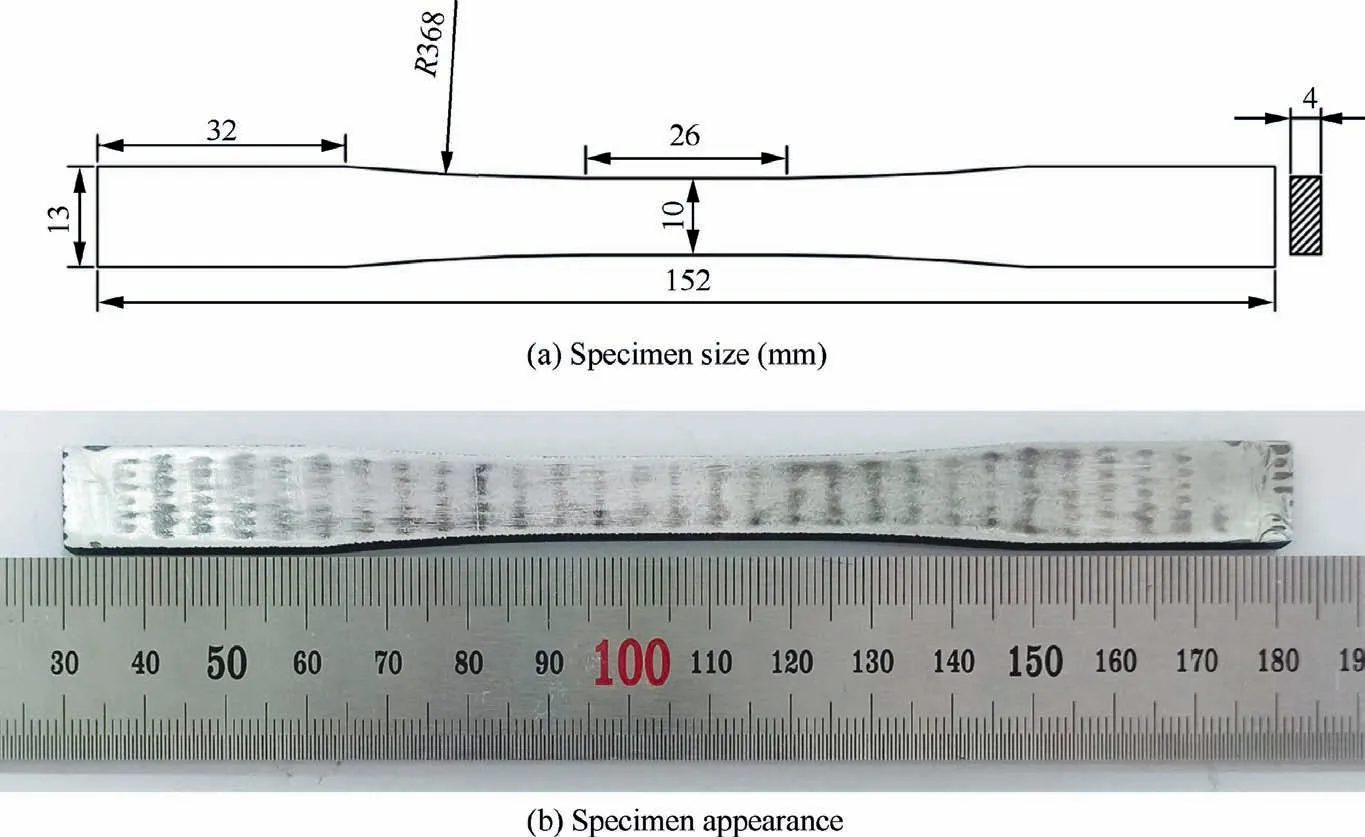
Fig. 2 Tensile test specimen of 3DAW-CF/Al composites.
3. Geometrical model of yarns and composites
3.1. Microscale representative volume element (RVE) model of yarns
The morphology of yarns in the 3DAW-CF/Al composites and their microstructure are illustrated in Fig.3(a)and(b),respectively. The matrix alloy between the weft and warp yarns was purified without any defects,such as impurities or voids.Inside the yarns, carbon fibers were arranged in the matrix alloy homogeneously. The matrix alloy was impregnated into the interspace of fibers thoroughly. The yarns were free of any casting defects, such as microscopic shrinkage and porosity.The weft and warp yarns comprised the carbon fibers and matrix alloy (Fig. 3(a)). Therefore, the yarns could be considered unidirectional fiber-reinforced aluminum matrix composites.The mechanical properties of the yarns could be evaluated by calculating the equivalent mechanical behavior of the unidirectional aluminum matrix composites with the same fiber volume fraction.The fiber zone inside the SEM photograph of the yarns (Fig. 3(b)) was identified by utilizing Image-Pro Plus software. Then, the total fiber area inside this SEM photograph was calculated. The fiber volume fraction in the yarn impregnated by alloy (Vf= 76% ) was obtained through dividing the total fiber area by the total area of the SEM photograph.
In accordance with the microstructure of the yarns (Fig. 3(b)), the fiber arrangement in the matrix alloy was assumed to be homogeneous and in a hexagonal close-packed pattern,as shown in Fig.4(a).In consideration of the periodic distribution characteristic of fibers in Fig. 4(a), an RVE model was extracted from Fig. 4(a) and was constructed, as shown in Fig. 4(b). Numerous previous studies have demonstrated that the mechanical properties of unidirectional composites can be predicted using an RVE with hexagonal close-packed arrangement of fibers.21,22In this RVE model, the fiber diameter D was 6 μm; the fiber volume fraction Vfwas equal to 76%, which was identical to the realistic fiber volume fraction measured from the microstructure of yarns (Fig. 3(b)). The geometric parameters of WCand LCof the RVE model could be determined as follows:
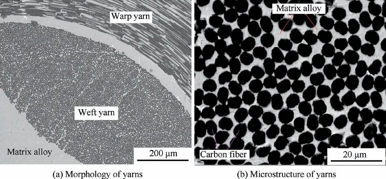
Fig. 3 Microstructure of yarns in 3DAW-CF/Al composites (SEM).
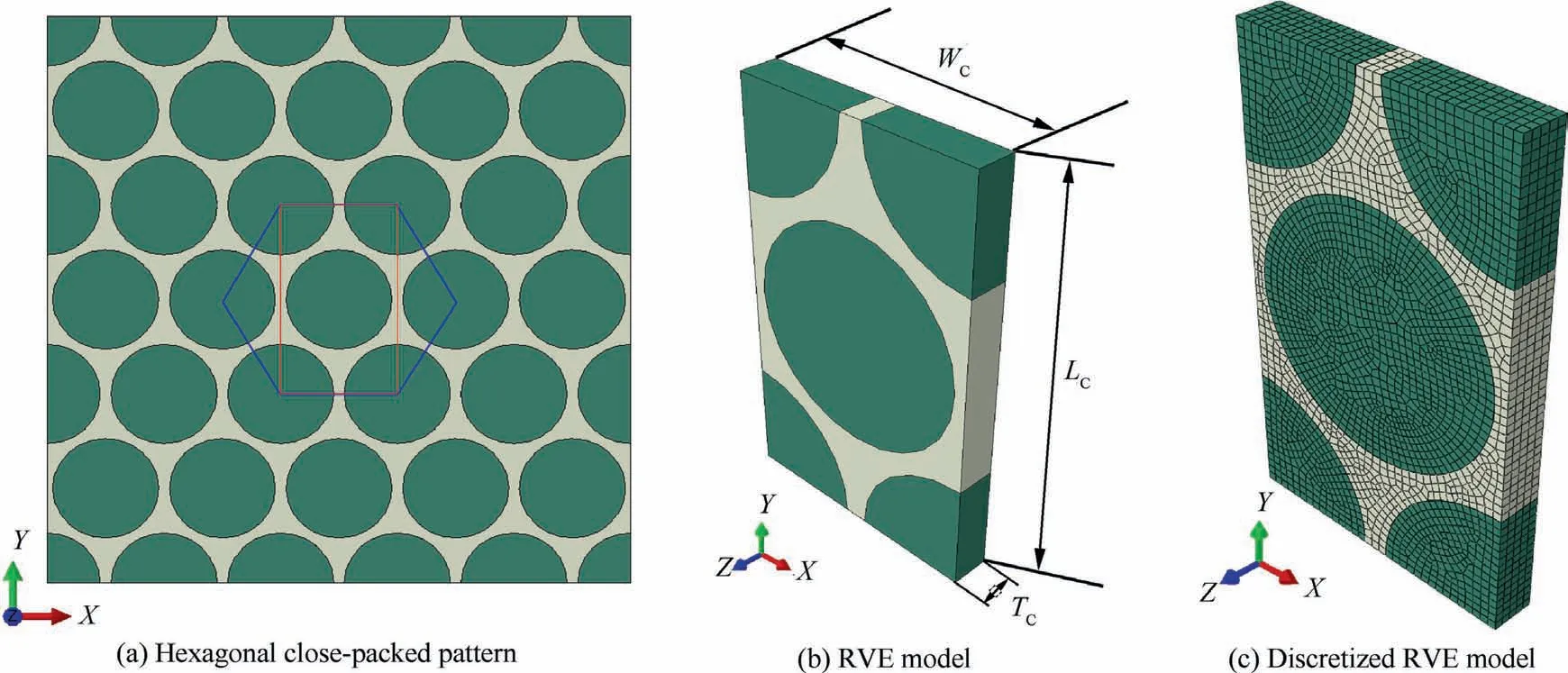
Fig. 4 Microscale RVE of yarns and discretization of the RVE model.

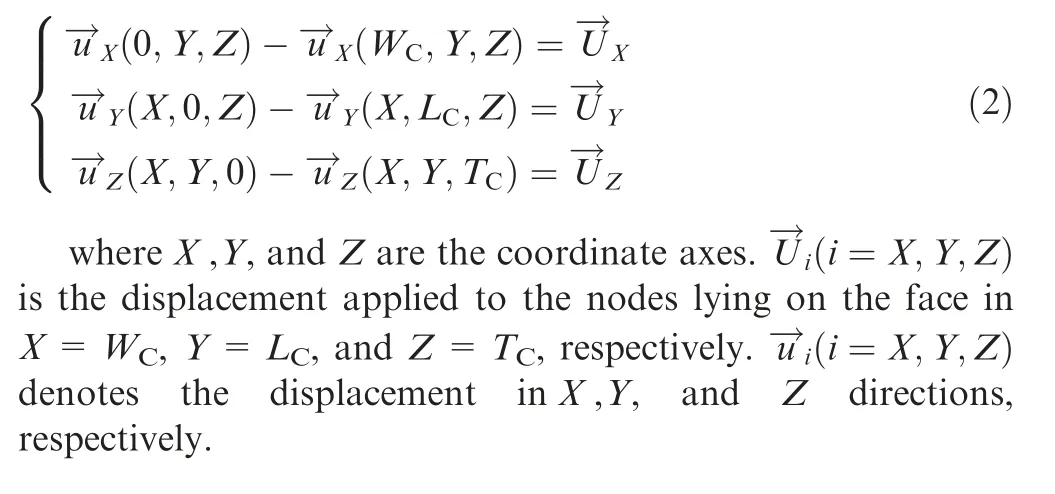
The RVE consisted of the fibers, the matrix alloy, and the interface between them, in which WCand LCwere 6.6 and 11.4 μm, respectively. The fibers were extremely long with respect to their diameter in the yarns; hence, the out-of-plane depth of the RVE model (TC) was inconsiderably critical as it was assumed to be 1.0 μm with periodic boundary conditions(PBCs) applied. The fibers and matrix alloy were discretized using C3D8R(an eight-node hexahedral element with reduced integration).The fiber yarn impregnated with matrix alloy was assumed to be equivalent to a unidirectional CF/Al composite.From our previous study,23the interface behavior plays an important role in determining the mechanical properties and failure of the unidirectional CF/Al composite. In the microscopic RVE, cohesive elements (a CZM) rather than a conode method was therefore employed to model the interface of fiber/matrix alloy, and the interface failure behavior inside the yarns could be considered.The discretization of the microscopic RVE model resulted in 12,075 elements in total,including 2695 elements in the matrix alloy and 9380 elements in the fibers, as shown in Fig. 4(c). PBCs should be implemented to the RVE model to ensure the displacement continuity and the traction continuity on the RVE surface simultaneously.The microscopic RVE model (Fig. 4(b)) was discretized using brick elements (C3D8R), and a periodic FE mesh was generated using a sweeping method. As a result, the node positions on the opposite faces of the RVE model were identical (Fig. 4(c)), which facilitated the application of PBCs to the microscopic RVE model. In this work, a set of equations for PBCs proposed by Xia and Curtin24was adopted and applied to the surface of the microscale RVE model, as show as follows:
3.2. Mesoscale FE model of composites
The mechanical behavior of the fabric CFAMCs was determined not only by the constituent material properties but also by the fabric architecture.The realistic structure of the 3DAWCF/Al composites should be described as accurately as possible to obtain a reasonable mechanical response of the composites via numerical simulation. The mesoscopic structure of the 3DAW-CF/Al composites along the warp and weft directions is presented in Fig. 5(a) and (b), respectively. In Fig. 5(a), a group of straight weft yarns were interlaced using the waved warp yarns regularly. The cross sections of most weft yarns are in a dual-surface lenticular shape, whereas the crosssectional shape of the warp yarns is relatively irregular, as shown in Fig. 5(b). Without loss of generality, a racetrack shape was used to model the cross section of the warp yarns.The resulted cross section and corresponding dimensions of the warp and weft yarns are illustrated in Fig. 6. On the basis of the results of optical microscopy observation (Fig. 5) and the architectural parameters of the 3DAW fabric (Table 1),the mesoscale structure model of the 3DAW-CF/Al composites was established, as shown in Fig. 6.

Fig. 5 Mesoscopic structure of 3DAW-CF/Al composites along warp and weft direction.

Fig. 6 Mesoscale structure model of 3DAW-CF/Al composites.
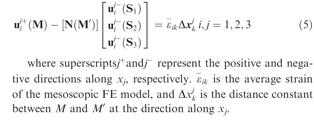
The model consisted of three parts, i.e., the warp yarns,weft yarns, and matrix alloy. An RVE is usually utilized in the micromechanical modeling of 3D angle-interlock woven composites.25,26However,the RVE of 3DAW-CF/Al composites (Fig. 7(a)) was not used in this study due to the few yarn layers in Z direction, as shown in Fig. 5, and the difference in architecture between the surface and inner part.At Z direction, the mesoscale FE model established in this paper (Fig. 7(b))had the same dimension and number of yarn layers as the real composite specimens, as shown in Fig. 5(a). At X and Y directions,only one periodic unit cell was established to reduce the calculation cost.This method has been successively used to predict the mechanical behavior of woven composites in the literature.27In the mesoscale FE model,the weft and warp yarns and the matrix alloy were discretized using C3D4(a four-node linear tetrahedral element in Abaqus). The interface between them was meshed using a cohesive element with zero thickness due to the fact that the interfacial thickness is ultra-thin compared with the size of yarns. The discretization of the mesoscale FE model of the composites resulted in 886906 elements in total, including 535984 elements in the matrix alloy and 350922 elements in the yarns, as shown in Fig. 7(c). In the mesoscale FE model, PBCs should be applied on the surfaces perpendicular to X and Y directions,while free boundary conditions were employed on the two faces perpendicular to Z direction. Node positions on the opposite faces of the discretized mesoscopic FE model could not keep identical, as shown in Fig. 7(c). As a result, the classical PBCs (Eq. (2))could not be applied on the faces perpendicular to X and Y directions. To address this issue, an improved PBCs (Eq. (5))was developed in this study.
As shown in Fig.8(a),the corresponding point of any point M on master plane AA′D′D on slave plane BB′C′C is M′,which falls in a triangle of tetrahedral element. The displacement of M′can be obtained by interpolating the node displacement surrounding this point, and its expression is as follows:

where{u }is the displacement matrix of point M′,[N(M′)]is the element shape function matrix of point M′in a triangle element on the slave plane, and{ δ }is the displacement matrix of the nodes surrounding point M′.
To program the improved PBCs through Python and apply it to the mesoscopic model,the positional relationship between point M′and the three nodes on the slave plane should be determined. As shown in Fig. 8(b), in the slave plane where-ΔS1S2S3is located, the position of any point M′can be represented as follows:

When coefficients x and y satisfy x ≥0,y ≥0,x+y ≤1,point M′locates in the interior of ΔS1S2S3(including the boundary).19The element shape function matrix [N(M′)]can be determined from the coordinates of point M′and the vertexes of triangle ΔS1S2S3.The improved PBCs of the mesoscopic FE model can be expressed as follows:
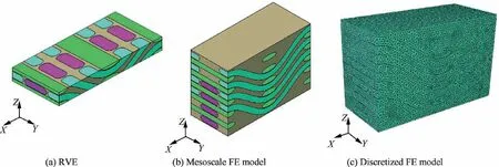
Fig. 7 RVE and mesoscale FE model of 3DAW-CF/Al composites.
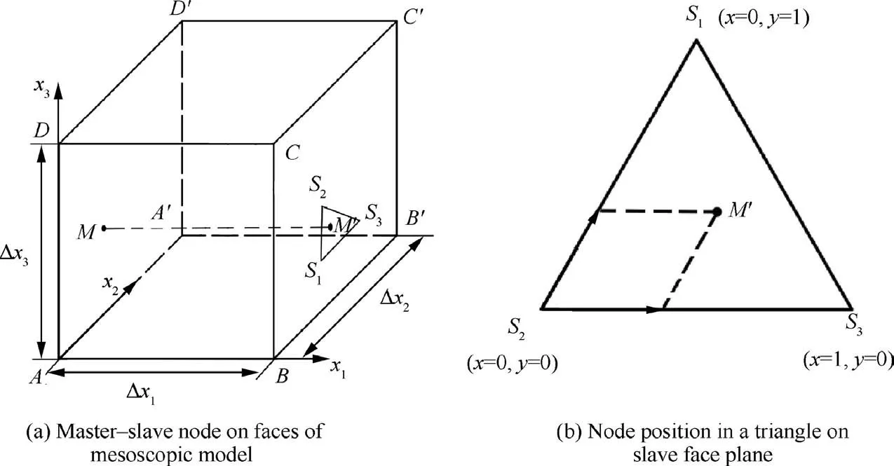
Fig. 8 Schematic of improved PBCs applied to mesoscopic FE model of composites.
4. Constitutive model and damage criterion
The matrix alloy in the 3DAW-CF/Al composites was modeled as an isotropic elastic–plastic solid material.In our previous studies,28the elastoplastic property parameters of the matrix alloy have been experimentally ascertained, as listed in Table 2.These parameters were utilized to define the elastic response and plastic deformation behavior of the matrix alloy.The von Mises yield criterion was adopted to justify the yield behavior of the matrix alloy,and the isotropic hardening rules were used in determining the plastic behavior. The plastic strain hardening of the yield surface can be defined by the yield strength σmy, strain hardening modulus EmH, and ultimate strength σmu, as shown in Table 2.
A ductile damage model was used to describe the damage initiation and evolution behavior of the matrix alloy. In this model, a scalar damage variable, which represents the degree of damage accumulation, was defined as a function of equivalent plastic strain, as shown as follows:
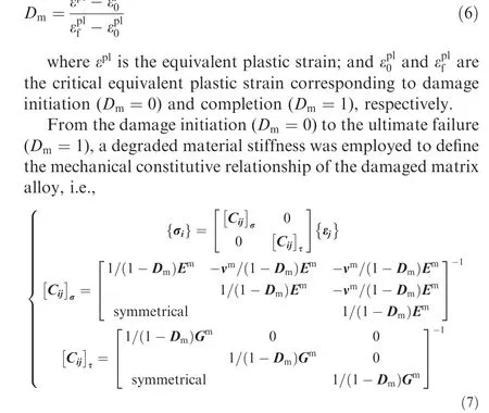
The fibers in the microscale RVE model were assumed as a transversely isotropic elastic solid body.According to previous studies,29the failure behavior of fibers plays an important role in determining the mechanical properties of a unidirectional CF/Al composite, especially under the axial tensile condition.The linear elastic behavior of the fibers was defined using elastic constants, as shown in Table 3. The maximum stress criterion was used to judge the fiber failure status in the microscale RVE of yarns, i.e.,
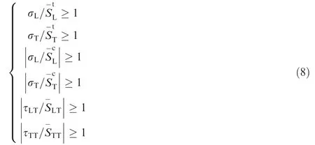
where σLand σTare the longitudinal and transverse stresses, respectively; and τLTand τTTare the longitudinal and transverse shear stresses of the integration point in fiber elements, respectively. The transverse isotropic strength parameters of fibers used in Eq. (8) are listed in Table 3. A stiffness matrix degradation method was used to formulate the mechanical behavior of the ‘‘failed” fiber, in which the elastic constants in Table 3 were multiplied by a positive discount factor less than 1.0.30
Fig.5 depicts that the 3DAW-CF/Al composites were composed of yarns and an aluminum alloy; the aluminum alloy was the matrix material,and the yarns were the reinforcement materials. However, the yarns, which were fully impregnated with the alloy(Fig.3),were essentially a unidirectional carbon fiber-reinforced aluminum matrix composite(UD-CF/Al composite) rather than pure fiber yarns. Therefore, in the mesoscopic FE model, the 3DAW-CF/Al composites should be modeled as UD-CF/Al composite-reinforced aluminum matrix composites rather than pure 3D woven fiber yarn-reinforced aluminum matrix composites. The mechanical response and failure behavior of the 3DAW-CF/Al composites were determined on the basis of the mechanical properties of the UDCF/Al composite (as a reinforcement material) and its specific 3D spatial woven configuration(3D angle-interlock structure).In this study,the yarns were equivalent to the UD-CF/Al composite, which possessed transversely isotropic properties.15Thus, in the mesoscopic FE model of 3DAW-CF/Al composites,the failure behavior of the yarns should be judged using a strength criterion for the transversely isotropic material. The Tsai-Wu stress failure criterion,31which has been proven to be appropriate and effective for unidirectional composites,was modified to predict the failure state of yarns in the mesoscopic FE model, i.e.,calculated on the basis of the strength parameters of the yarns,including the tensile strength Xt,Yt, the compressive strength Xc,Yc, and the shear strength S12,S23, which will be estimated via micromechanical simulations based on the microscale RVE in Subsection 5.1.
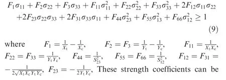

Table 2 Elastic and plastic properties of matrix alloy.

Table 3 Elastic constants and strength parameters of fiber in microscale RVE.23,30.
In the mesoscale FE model,the failure criteria of yarns(Eq.(9))were realized by programming a UMAT subroutine,which can be implemented in ABAQUS Standard. Before failure onset, the transversely isotropic linear elastic behavior of the yarns was defined using the elastic constants. When the stress status of the integration point in yarn elements satisfied the failure criteria, the degradation of the failed yarns initiated,and their elastic behavior was governed by a stiffness matrix,in which the elastic constants were multiplied by a discount factor less than 1.0. During the mesoscale FE simulation, the discount factor was calibrated carefully not only to reveal the mechanical degradation of the ‘‘failed” yarns but also to satisfy the stress consistency and calculation stability and convergence.
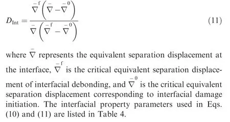
The fiber/matrix interface in the microscopic FE model and the yarn/matrix interface in the mesoscopic FE model have been represented using the cohesive element in Section 3. For the microscopic FE model, the fiber interface properties were ascertained in accordance with the determined interfacial parameters in our previous study concerning a unidirectional CF/Al composite, and the determining procedure has been reported in the literature.23At the mesoscale, the yarn interface was essentially composed of numerous local microscopic fiber interfaces on the outer edge of the yarns, as shown in Fig.3(a).Therefore,the yarn interface properties in the mesoscopic FE model were assumed to be equivalent to the fiber interface properties of the microscopic FE model. The interface behavior in the microscopic and mesoscopic FE models was defined using unified interfacial property parameters(Table 4). In this work, a bilinear traction–separation law based on CZM, which has been successfully applied in the micromechanical modeling of unidirectional aluminum matrix composites,32was utilized to describe the interfacial damage initiation, evolution, and debonding behavior.
Interfacial damage initiation was judged using the following maximum nominal stress criterion:

where tn,ts,and ttare the normal,first,and second in-plane shear stress components, respectively; and t0n, t0s, and t0trepresent the corresponding interfacial strength parameters.
When interfacial damage was initiated, the interfacial stiffness degraded with an increase in interfacial separation displacement in a linear way. The linear degradation rate was defined by introducing the following interfacial damage variable, monotonically varying from 0 to 1:
5. Results and discussion
5.1. Mechanical behavior of yarns
The mechanical response and failure behavior of yarns (76vol% unidirectional carbon fiber-reinforced aluminum composites) under axial and transverse loadings were calculated through FE simulations based on the microscale RVE. Under a transverse shear load,the stress and strain fields in the microscopic RVE (Fig. 4) were independent of the axial coordinate Z. Therefore, the transverse shear deformation could be analyzed using a generalized plain strain method. The deformed RVE was assumed to remain a paralelepipedon with plane faces.The transverse shear load was applied by assigning equal and opposite displacements to the nodes on the faces normal to X and Y coordinates, respectively; the nodes on the faces normal to Z coordinate were kept unconstrained.
To impose an axial shear load on the microscopic RVE,the corresponding nodes on the front face(Z=TC)and back face(Z=0) (Fig. 4(c)) were kept to undergo identical displacement, i.e., the same X and Y coordinates were constrained to guarantee that they have the same displacement in X,Y, andZ directions.The three DOFs of the nodes on the face(X=0)were constrained completely, whereas the nodes on the faces normal to Y coordinate were kept unconstrained. A displacement in Z direction was imposed to the nodes on the face(X=WC) to realize the application of axial shear load.

Table 4 Interfacial property parameters used in microscale and mesoscale model.23
In the postprocess of FE simulation results, the average strain and stress of the total elements in the microscopic RVE model after each loading increment were calculated using a volume average method, i.e.,

where σ-ijand εijare the homogenized stress and strain,respectively. σijand εijare the stress and strain components of elements in the RVE, respectively; and V is the volume of the RVE. A Python program was developed to calculate the average stress and strain due to the large number of elements in the RVE model. In this program, the volume and stress and strain components of each element were first extracted after each loading increment step. The average stress and strain of each loading step were then solved using Eqs. (12)and(13),respectively. The homogenized stress and strain data were finally generated from the average stress and strain at all loading steps.
The homogenized stress–strain curves are presented in Fig. 9, and the effective mechanical properties of the yarns are listed in Table 5. The tensile and compressive strength along the axial direction, i.e., parallel to the fiber axis, was 1422.65 and 726.19 MPa,respectively.The mechanical properties of yarns could be equivalent to those of a unidirectional fiber-reinforced aluminum composite, which could be evaluated using the rule of mixture proposed by Chamis.33The ultimate tensile and compressive strength of this composite along the fiber direction was mainly determined by the axial tensile and compressive strength of fibers. The remarkable difference between the tensile and compressive strength of yarns in the axial direction could be attributed to the much lower compressive strength than the tensile strength of the graphite fibers,as shown in Table 3. The difference in the axial tensile and compressive strength was also expected on the basis of previously published data on unidirectional fiber-reinforced aluminum composites.30,34The tensile and compressive strength along the transverse direction (perpendicular to the fiber axis) was significantly lower than that along the axial direction.The elastic modulus at the transverse direction was also lower than that at the axial direction. These results indicated that the yarns exhibited a remarkable transverse isotropic characteristic in their elastic and strength properties,which could be attributed to the different failure mechanisms under various loading scenarios.
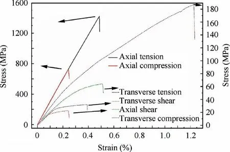
Fig. 9 Simulated stress-strain curves of yarns at different loading conditions.
The dominated failure mode of the yarns subject to axial and transverse tension loads is depicted in Fig. 10. Interfacial failure led to the damage and failure of matrix alloy at the middle tensile stage, as shown in Fig. 10(a). The final fracture of the yarns under the axial tension was mainly induced by the failure of fibers (Fig. 10(b)). The transverse fracture of the yarns was caused by the interfacial decohesion (Fig. 10(c))and rupture of matrix alloy (Fig. 10(d)), which resulted from the damage accumulation of the interface and matrix alloy.28,35
Under transverse shear loading, the local matrix alloy began to fail at the middle stage, as shown in Fig. 11(a). At the final stage,the fracture of the yarns was caused by the combined action of matrix failure and fiber breakage, as shown in Fig.11(b).When the yarns were subjected to axial shear loading,interface debonding initiated at the early stage(Fig.11(c)).However, no matrix alloy failure phenomenon was found in this process,and the fiber breakage led to the ultimate fracture of the yarns,as illustrated in Fig.11(d).Under axial and transverse compression loads, the final fracture of the yarns was dominated by the combined action of fiber breakage and interfacial debonding, as shown in Fig. 12. A similar phenomenon was experimentally observed in the fracture surface morphology of the unidirectional fiber-reinforced aluminum composites,34indicating the validity of the microscale numerical simulation.
5.2. Mechanical and failure behavior of composites under warp directional tension
The nonlinear FE software ABAQUS was utilized to analyze the tensile failure behavior of the 3DAW-CF/Al composites on the basis of the mesoscale FE model,in which the constitutive behavior and failure criteria of yarns were defined using the mechanical property parameters in Table 5.The definition of the local coordinate system for the weft and warp yarns was required due to their transversely isotropic characteristic.Especially,the curving shape of warp yarns led to the rotation of local axis with respect to the global coordinate system along the yarn axis,which resulted in variations in the effective modulus and strength in the global direction. The local coordinate systems following the spatial geometrical path of yarns were applied to each element of the warp and weft yarns, as shown in Fig.13(a)and(b),respectively.Local 1 direction was always parallel to the axis of the yarns, whereas local 2 and 3 directions were perpendicular to the axis of yarns.
Uniaxial tensile experiment on the 3DAW-CF/Al composites at the warp direction(X direction in Fig.7)was conducted,resulting in the experimental tensile stress–strain curves shown in Fig. 14. On the basis of the mesoscopic FE simulation results, the average strain and stress of the total elements in the deformed mesoscale model were calculated using the volume average method, as described by Eqs. (12) and (13) inSubsection 5.1.The macroscopic stress–strain curve was generated from the average strain and stress data obtained at all loading steps; it is also plotted in Fig. 14 to compare with the experimental curves. The results indicated that the predicted stress–strain curve was basically consistent with the experimental curves in the entire deformation process. At the initial tensile stage, the composites exhibited a linear elastic deformation characteristic, as denoted by the 0–A segment of the predicted curve in Fig. 14. Thereafter, the tensile stress increased with an increase in strain in a nonlinear way. The ultimate strength of the predicted curve was 385.59 MPa,which was slightly higher than that of the experimental curve(380.61 MPa). The microscopic porosity in the composites,which deteriorated the macroscopic mechanical properties,was not considered in the mesoscale FE model. The 3DAWCF/Al composites had uniquely nonlinear mechanical response behavior different from that of 3DAW-resin matrix composites, which has been investigated vastly in the past.36,37The unique nonlinear mechanical behavior(A-D segment of the predicted curve in Fig. 14) could be considered as a result of some microscopic damage or local failure during the middle and final tensile stages, as discussed below.

Table 5 Effective elastic constants and strength parameters of yarns.

Fig. 10 Failure mode of yarns subjected to axial and transverse tensile loads.

Fig. 11 Failure mode of yarns under transverse and axial shear loads.
Fig. 15 presents the progressive damage and failure behavior of the composites during the uniaxial tension process.Interfacial damage occurred first on the straight segment of the warp yarn and on the warp yarn near the weft yarn, as depicted by I and II regions in Fig. 15(a), respectively. Afterward, local matrix alloy damage initiated in the ultra-thin matrix region near the yarns (I and II regions in Fig. 15(b)).At the tensile strain of 0.1835%, local interfacial failure occurred on the surface of the warp yarns (I and II regions in Fig. 15(c)). Meanwhile, significant local damage of the matrix alloy occurred in the same locations. The interfacial failure was induced by the damage accumulation of the interface and matrix alloy, which in turn aggravated the matrix alloy damage in these regions(point I in Fig.15(d)).As a result of interfacial failure, the stress–strain response after point A(ε = 0.1835%) in Fig. 14 began to display a nonlinear characteristic with the increase in strain.
As tensile strain arrived at 0.5236%,local fracture occurred on several elements of weft yarns (point I in Fig. 15(e)) owing to the relatively poor tensile and in-plane shear strength in the transverse direction,as indicated by the result from microscale simulation in Subsection 5.1 (Fig. 9 and Table 5). The local failure of weft yarns did not lead to tensile stress degradation,but the tangent modulus descended with increasing strain after point B on the predicted curve,as shown in Fig.14.At the tensile strain of 0.9436%(point C in Fig.14),matrix alloy failure(Fig. 15(f)) initiated in the local regions where the damage propagation was limited due to the relatively thin thickness of the matrix alloy. Thereafter, local failure zones extended and propagated to the inner elements of weft yarns progressively with increasing external loading (Fig. 15(g)) because the loading capacity of the failed matrix alloy was definitely weakened. At the final tension stage, a serious fracture phenomenon emerged in most of weft yarns, and local failure occurred near the arc segment of warp yarns, as shown in Fig. 15(h). Consequently, the tensile stress began to fall down dramatically after the macroscopic stress–strain curve reached the peak value, as denoted by point D in Fig. 14.

Fig. 13 Definition of local material coordinate systems for warp and weft yarns.
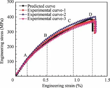
Fig. 14 Experimental and predicted stress-strain curves of 3DAW-CF/Al composites under warp directional tension.
The fracture morphology of the post-tensile specimen at the warp direction is presented in Fig. 16. Complex deformation and failure characteristics could be observed at the mesoscale and microscale from these photographs. The main failure mechanism under warp directional tension condition was the transverse failure of weft yarns and the axial fracture of warp yarns, as denoted in the low-magnification SEM fractography(Fig. 16(a)). The former was caused by the poor strength of yarns under transverse tensile loading, as revealed in the microscale simulation in Subsection 5.1. The latter resulted from the combined action of axial tensile and shear loading.As a result,the fracture micrograph of the warp yarns displays a quasi-ductile fracture feature with limited fiber pullout and flexure phenomenon(Fig.16(b)),which agreed with the results of microscale simulation. The agreement between the experimental and numerical results demonstrated the validity of the multiscale modeling in this study.
5.3. Mechanical and failure behavior of composites under weft directional tension
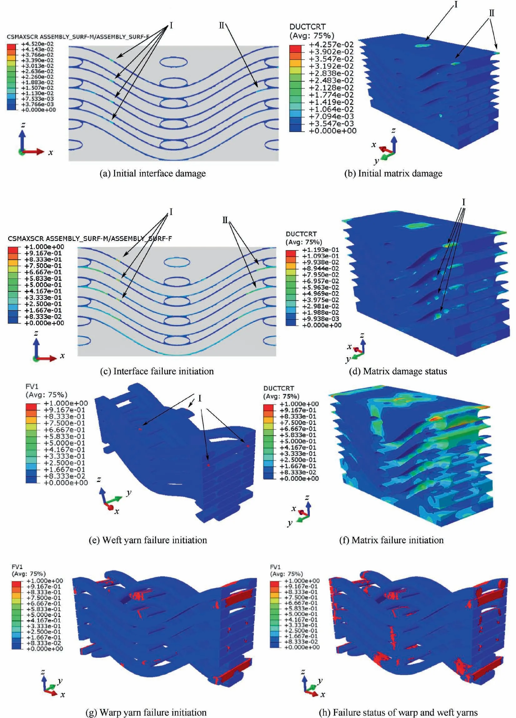
Fig. 15 Damage evolution and failure process of 3DAW-CF/Al composites under warp directional tension.
The experimental and predicted stress–strain curves of the 3DAW-CF/Al composites under weft directional tension condition are presented and compared in Fig. 17. The variation tendency of the predicted curve was roughly in accordance with the experimental one. Nevertheless, the initial elastic modulus and ultimate strength of the composites were underestimated. The straight weft yarns were mainly subjected to axial tensile loading, whereas the warp yarns were purely in transverse tensile stress state during the weft directional tensile process. The failure behavior of the yarns was judged using a modified Tsai–Wu criterion,in which the interaction of different stress components was considered by introducing fairly low in-plane and out-plane shear strength.38The tensile stress–strain curve could be divided into a linear elastic period and a nonlinear deformation period by point E(at the tensile strain of 0.1698%). The initial elastic modulus, ultimate strength,and fracture strain in the weft direction were 63.1 GPa,268.3 MPa, and 0.698%, which were 1.05 times higher, 0.70 times lower,and 0.54 times lower than those in warp direction,respectively. Hence, the deformation behavior and failure mechanism under weft directional tension, which might differ from those under warp directional tension, should be further investigated.
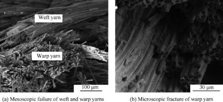
Fig. 16 Fracture morphology of 3DAW-CF/Al composites at warp directional tension condition.
The detailed damage evolution and failure behavior during weft directional tensile process are listed in Fig.18.At the tensile strain of 0.002%,initial interfacial damage occurred on the warp yarn surface perpendicular to Y direction(the weft direction), as shown in Fig. 18(a). Afterward, damage happened at the local portion of the matrix alloy, as shown in Fig. 18(b),which led to a slight descent in the tangent modulus of the curve,as denoted by point E in Fig.17.With increasing tensile strain,local failure was observed at the interface near the edge of the warp yarns and then extended to the adjacent corners between the weft and warp yarns (Fig. 18(c)). These edges on warp yarns were perpendicular to the tensile loading direction; therefore, the interface was liable to debonding under normal stress state.39,40Under the action of interfacial failure and matrix damage, a local transverse failure appeared on the surface of warp yarns,as shown in Fig.18(d).The main reason could be attributed to the relatively low strength of yarns when subjected to loading perpendicular to their fiber axis, as clarified on the basis of the microscale simulation results in Subsection 5.1. The failure of warp yarns led to an obvious decrease in the tangent modulus of the curve, as denoted by point F in Fig. 17.
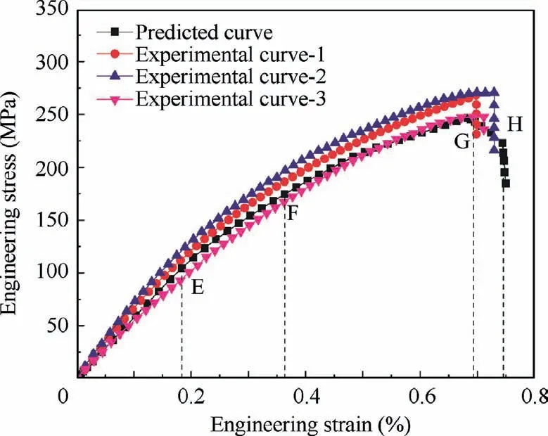
Fig. 17 Experimental and predicted stress-strain curves of 3DAW-CF/Al composites under weft directional tension.
As the external tension load increased continually, matrix alloy failure was observed in the local region where the matrix pocket was ultra-slender, as shown in Fig. 18(e). In this region, the matrix damage originated from interfacial debonding and expanded rapidly, and the matrix alloy was highly vulnerable to crack due to the limited space for damage propagation. A slight failure of the weft yarns was also observed in Fig. 18(f), which corresponded to a considerable high tensile stress level on the tensile curve, as shown by point G in Fig. 17. After the occurrence of failure in weft yarns, the failed zone of warp yarns expanded around the arc segment rapidly. Meanwhile, increasing failed elements were detected in the cross section of weft yarns (Fig. 18(g)).This condition led to the catastrophic failure of the composites and a sudden decrease in tensile stress (point H in Fig. 17), implying that the weft yarns were the dominant load-bearing component at the final stage under weft directional tension condition.
Fig.19 presents the fracture morphology of the post-tensile specimen obtained from SEM analysis.The low-magnification micrograph (Fig. 19(a)) clearly shows the transverse cracking mode of the curving warp yarns, as denoted by point I. This mode was a result of fiber exfoliation from the matrix alloy due to the interfacial debonding under the tensile loading perpendicular to the axis of warp yarns.On the contrary,the weft yarns exhibited the characteristic of axial fracture with a brittle rupture feature, as depicted by point II. The detailed microstructure of the axial fracture surface is illustrated in Fig. 19b. From this micrograph, the axial fracture of weft yarns was more flat, and relatively limited fiber pullout was observed compared with the axial fracture morphology of the warp yarns in warp directional tension process (Fig. 16(b)). Fiber pullout and accompanying interface slipping play an important role in energy absorption and promoting the mechanical properties of unidirectional fiber-reinforced aluminum composites.41,42Hence, the composites subjected to tensile loading in the weft direction exhibited relatively low strength and fracture strain compared with those under tension condition in the warp direction due to the absence of interfacial slipping and fiber pullout.The results of simulation and experiment indicated that the failure of matrix and the axial fracture of warp yarns, which were induced by the interfacial damage accumulation and transverse failure of warp yarns, were the dominant failure mechanisms of the composites during the weft directional tensile process.
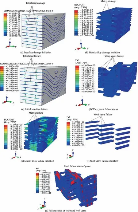
Fig. 18 Damage evolution and failure process of 3DAW-CF/Al composites under weft directional tension.
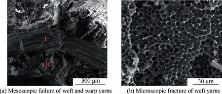
Fig. 19 Fracture morphology of 3DAW-CF/Al composites at weft directional tension condition.
6. Conclusions
A multiscale FE model of novel 3D angle-interlocking woven fiber-reinforced aluminum composites was developed by incorporating the progressive damage of matrix alloy,the transverse isotropic failure of fiber/yarn,and the decohesion of interface.Under warp and weft directional tension conditions, the complex damage evolution and failure mechanisms of the composites were investigated through multiscale numerical simulation and experiment. The following conclusions were drawn from this study.
(1) The predicted macroscopic stress–strain curves and the failure modes from the numerical simulation are basically consistent with the experimental ones obtained from the warp and weft directional tensile testing,which demonstrates the validity of the multiscale modeling.
(2) During the warp directional tension process, the failure of interface, weft yarns, and matrix alloy occurs successively at the early and middle stages. The axial fracture of warp yarns is responsible for the ultimate failure of the composites, which results in a quasi-ductile fracture surface with the characteristic of limited fiber pullout and flexure.
(3) Under the weft directional tension condition, interfacial failure and transverse cracking of warp yarns occur at the early and middle stages, respectively. The failure of matrix alloy and weft yarns emerges almost simultaneously at the last stage. The brittle fracture of weft yarns along the fiber axis leads to the catastrophic failure of the composites.
(4) The lower ultimate strength and fracture strain at weft directional tension condition can be attributed to the lower weft density and the more serious brittle fracture of weft yarns compared with the quasi-ductile fracture of warp yarns at warp directional tension condition.
Declaration of Competing Interest
The authors declare that they have no known competing financial interests or personal relationships that could have appeared to influence the work reported in this paper.
Acknowledgments
This study was co-supported by the National Natural Science Foundation of China (Nos. 51765045 and 51365043), the Aeronautical Science Foundation of China (No.2019ZF056013), and the Jiangxi Provincial Natural Science Foundation (No. 20202ACBL204010).
 CHINESE JOURNAL OF AERONAUTICS2021年8期
- CHINESE JOURNAL OF AERONAUTICS的其它文章
- A novel virtual material layer model for predicting natural frequencies of composite bolted joints
- Multi-layered plate finite element models with node-dependent kinematics for smart structures with piezoelectric components
- Modeling bending behavior of shape memory alloy wire-reinforced composites: Semi-analytical model and finite element analysis
- Sequential ensemble optimization based on general surrogate model prediction variance and its application on engine acceleration schedule design
- Transition prediction and sensitivity analysis for a natural laminar flow wing glove flight experiment
- Modeling on mechanical behavior and damage evolution of single-lap bolted composite interference-fit joints under thermal effects
