A review of numerical analyses and experimental characterization methods for forming of textile reinforcements
Bio LIANG, Philippe BOISSE
a School of Mechanical Engineering, Northwestern Polytechnical University, Xi’an 710072, China
b Universite´ de Lyon, CNRS, INSA-Lyon, LaMCoS, F69621, France
KEYWORDS Experimental characterization;Forming;Liquid Composite Molding;Numerical analysis;Textile reinforcements
Abstract The forming of textile reinforcements is an important stage in the manufacturing of textile composite parts with Liquid Composite Molding process.Fiber orientations and part geometry obtained from this stage have significant impact on the subsequent resin injection and final mechanical properties of composite part.Numerical simulation of textile reinforcement forming is in strong demand as it can greatly reduce the time and cost in the determination of the optimized processing parameters,which is the foundation of the low-cost application of composite materials.This review presents the state of the art of forming modeling methods for textile reinforcement and the corresponding experimental characterization methods developed in this field. The microscopic, mesoscopic and macroscopic models are discussed. Studies concerning the simulation of wrinkling are also presented since it is the most common defect occurred in the textile reinforcement forming.Finally,challenges and recommendations on the future research directions for textile reinforcement modeling and experimental characterization are provided.
1. Introduction
The progress made in reducing aircraft weight in recent decades is largely due to the application of composite materials,leading to a decrease in fuel consumption and environmental pollution. In particular, the latest long-range aircraft, such as the Airbus A350 or the Boeing 787, in which more than 50% of their structures are made of composite parts.1–4However, the manufacturing process of composite part is rather complicated and achieving a defect-free composite part is still a great challenge despite the progress has been made.To make the increasing applications of composite materials possible, it is in strong demand for replacing the expensive trial-anderror based experimental methods with the numerical simulations in the optimization of fabrication parameters. The manufacturing of textile reinforced composite part generally requires the preforming of dry textile reinforcement and a subsequent injection of a resin (i.e., Liquid Composite Molding(LCM)).Composite part can also be obtained by thermoforming prepregs made of textile reinforcement and uncured matrix. In both cases (LCM and thermoforming processes),the forming operation is dominated by the deformation of textile reinforcement, and the basic physics of textile reinforcement deformation is the deformation of continuous fibers and their interactions.
The objective of this review is to present computational and experimental methods for the forming of textile reinforcements. The multi-scale nature of textile reinforcements leads to the development of models at different scales. Simulation models at the microscopic scale (fiber scale), the mesoscopic scale (yarn scale), and the macroscopic scale (composite part scale) are presented. Currently, the majority of forming simulations are carried out at macroscopic scale. Therefore, the macroscopic simulation approaches are the core of this review.In particular,the difficulty of developing shell models given the specific physics of textile reinforcement deformation is discussed. Wrinkle is a frequent defect when draping textile reinforcements.The analysis methods of onset and development of wrinkles are also presented.Mechanical tests specifically developed to characterize mechanical behaviors of textile reinforcements are discussed.Numerous studies have concerned the inplane shear characterization, which is the major deformation mode of fabrics when draped over a double-curved surface.Other mechanical tests are also developed:biaxial tensile,compaction and bending tests. Bending deformation is proved to be closely related to the development of wrinkles in the forming of textile reinforcement.It receives increasing attentions in the past years and becomes a hot topic in the mechanical characterization and numerical modeling for textile reinforcements.
2. Numerical modeling approaches for textile reinforcements
Textile reinforcements are made of thousands of continuous fibers, they can be 2D fabrics (e.g., plain, twill or stain),2.5D interlock fabrics (different layers are joined together by weaving), 3D fabrics or Non-crimp fabrics (NCF). Due to the inherent multi-scale nature of textile reinforcements, three research scales are usually defined in the composites forming domain (Fig. 1): macroscale (i.e., structure scale with dimension order of centimeters to several meters), mesoscale (i.e.,yarn scale with dimension order of one to several millimeters)and microscale (i.e., fiber scale with dimension order of micrometers). Consequently, the approaches to model the forming of textile reinforcements can also be classified into three primary families that are related to the scale in which the analysis is made:microscopic modeling approaches,mesoscopic modeling approaches and macroscopic modeling approaches. Within the multi-scale modeling strategies,sequential approach can be used in which the lower-scale model is homogenized and the results are used as inputs of material law in the higher-scale modeling.The three scale modeling approaches can be related to each other by the sequential approach or performed independently. Macroscopic modeling approaches,due to their high computation efficiency and accuracy, are the most popular modeling method in industry and academy,they are the core of this review paper and a comprehensive review would be presented.
2.1. Microscopic modeling approach
In the microscopic modeling approaches, textile reinforcements are seen as composed of individual fibers undergo large deformation and their contact-friction interactions are explicitly modeled.Many literatures related to the microscopic modeling are available and they can be classified into two categories: one is called the digital element method and the other is the 3D beam finite element method. The digital element method was firstly developed by Wang and Sun,5which was initially intended for modeling yarn deformation at mesoscale. Zhou et al.6and Miao et al.7extended this method and employed it for modeling 2D fabrics at microscale,where yarn was assumed to be an assembly of virtual fibers and each virtual fiber was discretized by the digital rod or beam elements(Fig. 2). Here, it needs to be noted that in the digital element method, the number of virtual fibers in the yarn is not necessarily the same as the actual amount of fibers in the real yarn,virtual fiber is an approximation of a sets of real fibers in terms of mechanical stiffness. Yousaf et al.8and Daelemans et al.9have applied the digital element method to simulate the deformation of 2D and 3D fabrics at microscale,respectively.Good agreement with experiments was observed, indicating the prediction capability of digital element method for deformation simulation of textile reinforcements.
3D beam finite element method was another widely used microscale modeling approach, firstly proposed by Durville,10,11in which each fiber in the yarn was discretized with a cross-section deformable 3D beam element and the contact-friction interactions between fibers were considered.Fig. 3 shows a predicted configuration of woven textile reinforcements after the weaving process with the 3D beam finite element model, the evolution of fiber trajectories and the changes in cross-sections shape are reproduced as seen in the actual textile reinforcements.
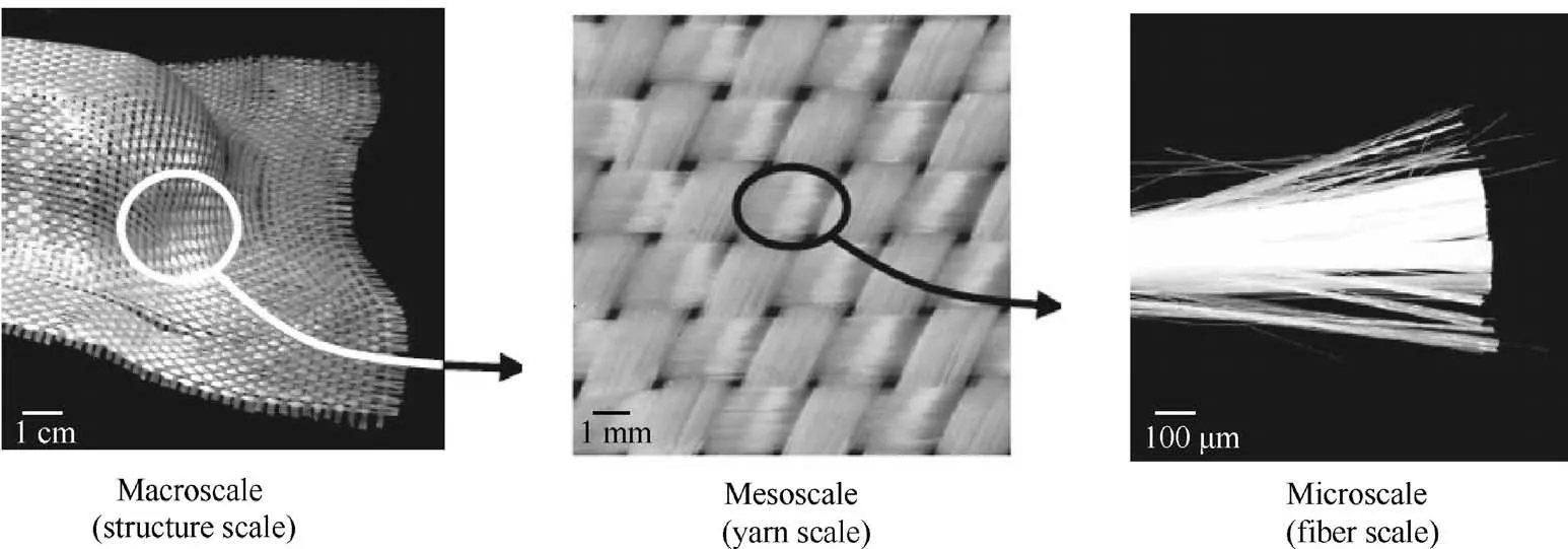
Fig. 1 Schematic of three research scales defined for textile reinforcements.

Fig. 2 Concept of digital element method applied for modeling yarns of textile reinforcement.7
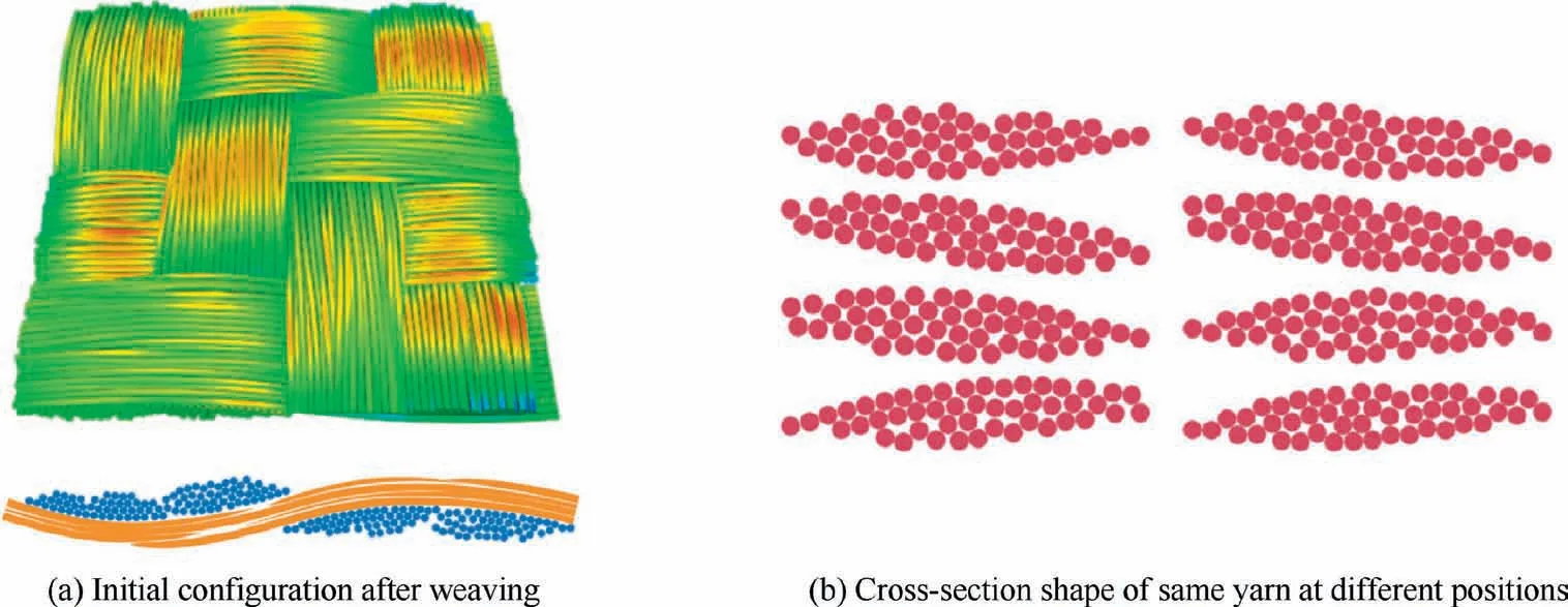
Fig. 3 3D beam finite element simulation of twill fabric.10
In both the digital element method and 3D beam finite element method,fiber is generally modeled as transverse isotropic material with a relative low transverse stiffness. The key issue related to the microscopic modeling approaches is the high computation cost brought by the large number of elements and contact pairs, confining its application only in a small scale of textile reinforcements regarding the current computation capability.
2.2. Mesoscopic modeling approach
The basic idea of mesoscopic modeling approaches is regarding textile reinforcements as composed of a sets of yarns interlacing together and interactions between yarns are considered.Based on the dimension size of textile reinforcement that these mesoscopic modeling approaches are applied, they can be divided into two categories: approaches concerning the single unit cell and approaches for the complete textile reinforcement.
2.2.1. Mesoscopic modeling approaches concerning the single unit cell
Unit cell (also called RVE (Representative Volume Element))is the smallest periodic structure of textile reinforcement,composed by several yarns weaving together. Geometry accuracy of unit cell has significant effect on the mesoscopic modeling.12Yarn cross-section varies along yarn trajectory due to the local contact between yarns. To capture this characteristic, Hivet and Boisse13proposed a consistent geometry reconstruction method, the influence of local contact on the yarn crosssection shape was accounted in their approach. Wang et al.14conducted a similar work in their unit cell reconstruction for an unbalanced reinforcement.Apart from the traditional optical method (e.g., microscope) to acquire yarn geometry information, Computed Tomography (CT) is another popular method since it is non-destructive and allows to get geometry information inside material.Naouar et al.15have built the unit cell geometry of textile reinforcement directly from a stacking of CT scanning images, 3D solid elements then were used to discretize the yarn.Fig.4 shows a RVE structure reconstructed directly from the scanning CT images.16However, in the CT images of highly compacted reinforcement, interconnection and nesting exist between fiber tows, posing challenges in the fiber tow reconstruction. To cope with this challenge, a novel image processing methodology was proposed to accurately separate fiber tows in low resolution μCT scans of real textile specimens by Wijaya et al.17,18This methodology can reconstruct various unit cells with an arbitrary number of layers and nesting configurations from given μCT images,which were readily converted to finite element models.
Besides using 3D solid elements, rod or beam elements are also frequently used as they can greatly reduce the number of finite elements. Wang and Sun5and Kawabatta et al.19have used the rod-element to model yarn deformation. They assumed yarn cross-section keeps constant. Actually, yarn cross-section shape would deform due to the local compaction force. To cope with this issue, Gao et al.20developed a crosssection deformable beam element to model yarn deformation,demonstrating a great potential in the large-scale mesoscopic modeling.
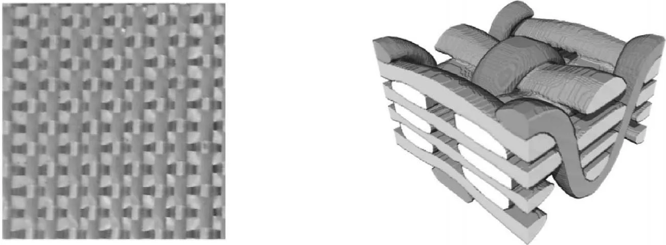
Fig. 4 3D orthogonal woven fabric image (left) and its CT reconstruction (right).16
Yarn is composed of parallel fibers and can be taken as transverse isotropic material. Badel et al.21, Nguyen et al.,22Naouar et al.15,16and Wang et al.14employed transverse hypoelastic material model to simulate yarn’s mechanical behavior. Analyses of woven unit cell subjected to tension,in-plane shear and compression have been performed based on the hypoelastic material model. Good agreement was observed between simulation and experiment for yarn’s shape.The hypoelastic material model requires the use of an objective derivative to relate the rate of stress and strain, and the fiber direction of yarn needs to be accurately tracked. Therefore,the stress calculation process is relatively complicated. To overcome this drawback, hyperelastic material model is proposed to simulate yarn’s mechanical behavior by Charmetant et al.23. Four types of yarn deformation modes (elongation,compaction, cross-section distortion and longitudinal shearing) were considered and the strain energy was based on the invariants of strain tensor. The hyperelastic material model was validated with a biaxial tension test and picture frame test in a single RVE deformation.
It needs to be noted that monotonic loading is general applied in the forming of textile reinforcement. In this case,both the hypoelastic material model and the hyperelastic model have good characterization of yarn’s loading mechanical behavior. However, if the cyclic loading is applied, energy dissipation generally would be observed. In this case, the hypoelastic material model is more consistent with yarn’s loading–unloading behavior compared to the hyperelastic model as it is able to account for the energy dissipation.
2.2.2. Mesoscopic modeling approaches for the forming of complete reinforcement
Gatouillat et al.25developed a mesoscopic model for macroforming of woven fabrics, where yarn was simplified as shell structure in contact-friction with its neighbors and hypoelastic material model was adopted to characterize yarn’s mechanical behavior. This model was validated with double-dome and hemispherical structure forming. Recently, Iwata et al.26used the model developed by Charmetant et al.23to perform a local mesoscopic analysis after a macroscopic draping simulation,local yarn buckling and yarn slippage was correctly predicted.By a different approach,Wang et al.27conduced a mesoscopic analyses of the draping of 3D woven reinforcements based on macroscopic simulations, in which an embedded mesoscopic geometry was first deduced from the macroscopic simulation of the draping.
For the draping of non-crimp fabrics,a mesoscale modeling method was presented by Creech et al.28Yarns were discretized with 3D solid elements and stiches were discretized with bar elements (Fig. 5). With this modeling method, yarn slippage between neighbor layers in the draping process can be predicted. However, in Creech’s model, simplification has been made for the shape of yarn cross-section and is implicitly considered. To deal with this issue, Thompson et al.29and El Said et al.30proposed to build a more realistic yarn shape through the application of digital element method. They have used shell elements to discretize yarn’s surface and beam elements to discretize stich for the non-crimp fabric. Modeling yarn surface with shell elements would result in no-resistance to transverse loading. To handle this issue, they have added shell element supports along the length of yarns to provide transverse stiffness. However, their model does not preserve the physical properties of real yarns, therefore it considers more the kinematic behavior of textile reinforcement rather than its actual mechanical response.
2.3. Macroscopic modeling approach
2.3.1. Kinematic drape modeling approach
These methods also called pin-jointed net method or fishnet algorithm.31–35They are purely geometric and the position of a woven fabric draped over a double-curved surface is determined based on the following assumptions: (i) the yarns are inextensible; (ii) the yarns have no bending stiffness; (iii) there is no slippage at the cross over of warp and weft yarns;(iv)the relative rotation between the warp and weft yarns at cross over are free;(v)there is no sliding between the yarns and tools after coming into contact. The principle of the pin-jointed net method is shown in Fig.6.From the knowledge of the position of points A and A’, the position of point B can be determined from the previous assumptions. From the known position of points A and A’, the position of point B can be determined on the basis of above assumptions. The lengths AA1and A’A’1are fixed to the length of the net. By considering all curves AA1and A’A’1on the tool,point B is determined when points A1and A’1are coincident.This is achieved by solving a scalar problem very rapidly. This is the advantage of the method which has a very low calculation cost. The algorithm is initiated from the position of a starting point and the warp and weft directions. The geometry of the tool is a given and must be described analytically or by curved or plane panels.The method is very numerically efficient and can be used during the design phase in the engineering office. More detailed presentations of the method and examples can be found in Refs.35–39The limitations of the method are nevertheless strong. The mechanical behavior of the reinforcement on the one hand and the boundary conditions in force on the other hand are not taken into account in this approach. However,these two aspects strongly condition the draping of a textile reinforcement.

Fig. 5 Meso-mechanical model composed of solid element and bar element for NCF fabric.28
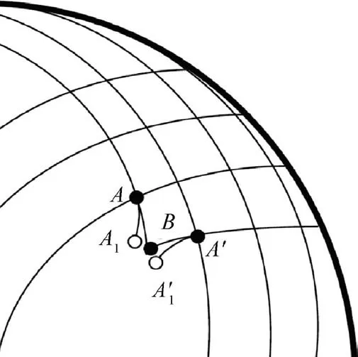
Fig. 6 Principle of pin-jointed net method.
2.3.2. Continuum mechanics approach
Textile reinforcements are composed of continuous fibers whose diameter is of the order of a few microns. These fibers can have relative movements and in particular sliding between fibers. Nevertheless, in most cases a continuous medium assumption can be made. Fig. 7(a) shows that straight lines drawn on a reinforcement before deformation become curved after deformation but remain continuous. The reinforcement can be considered as a continuous medium. However, this hypothesis has limitations for the forming of complex shape with small curvature radius. For instance, Fig. 7(b) shows the forming result of prismatic shape. Obvious fiber sliding can be noted, which demonstrates the loss of continuity in the forms of gap defect.40,41
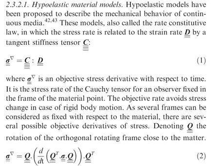
The Green-Naghdi and Jaumann objective derivatives are usually used in hypoelastic constitutive equations. But in the case of fibrous materials, the objective derivative must be based on the direction of the fiber.In the case of a textile membrane, it consists of two directions of fibers warp and weft as shown in Fig. 8. In the current configuration, the unit vectors in the warp and weft fiber directions are respectively:

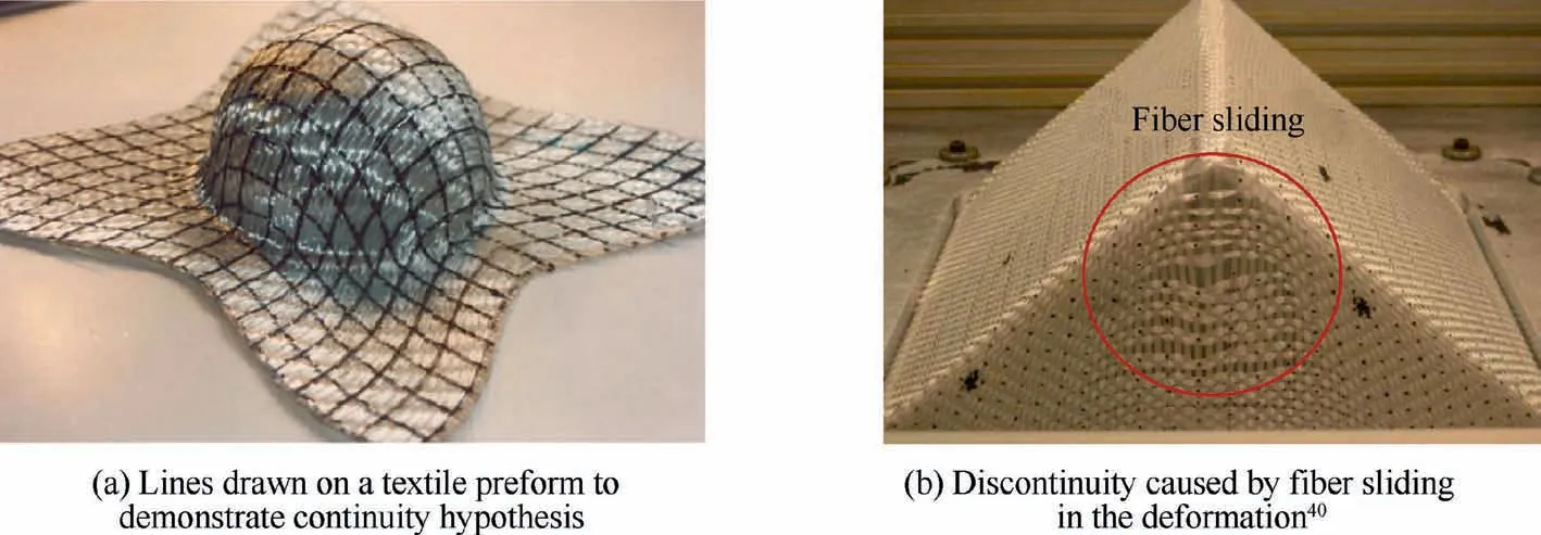
Fig. 7 Validation of continuous deformation assumption for textile reinforcement.
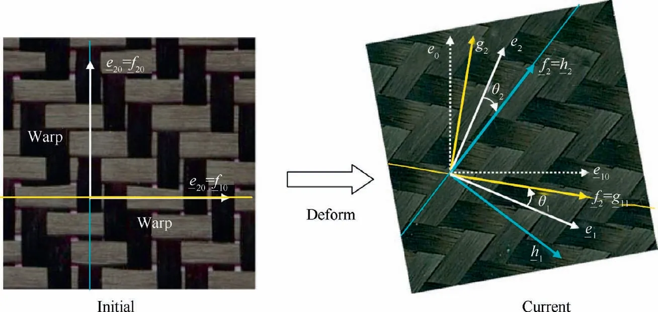
Fig. 8 Two orthogonal frames based on warp and weft fiber directions for 2D textile reinforcement.
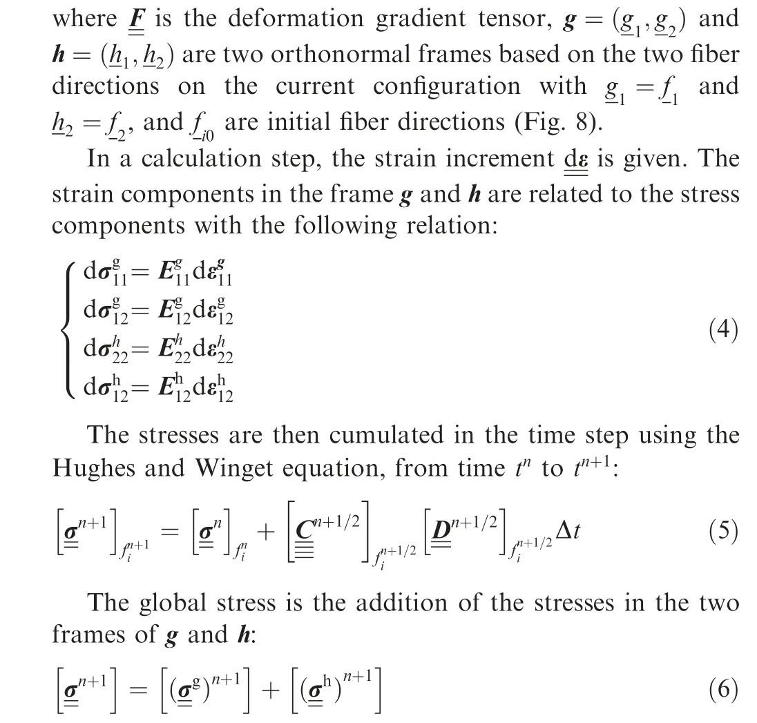
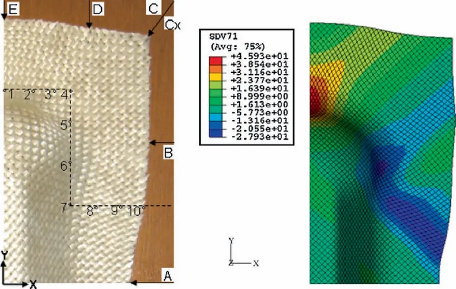
Fig. 9 Simulation of the ‘Double-Dome’ forming for a 45°orientation of yarns.44
More details about this approach can be found in Refs.44,45A double-dome forming benchmark was launched with the hypoelastic material models.46–50Fig.9 presents the simulation using the above approach and a comparison with experiment.2.3.2.2.Hyperelastic material models.The mechanical behavior of textile reinforcements during forming can also be described by hyperelastic models. Rubber-like materials at large strains were the first to be modeled by isotropic hyperelastic models.51,52Anisotropic models have also been developed for certain elastomers53–55or biomaterials.55,56
Peng et al.57have developed a simplified hyperelastic constitutive model to characterize the anisotropic and large deformation behavior of 2D textile fabrics.In their model,the strain energy function was decomposed into two parts representing fiber stretches and angle change between the weft and warp yarns (in-plane shearing). The two deformation modes were assumed to be independent to each other and there has no coupling. To include the coupling effect between the fiber tension and in-plane shear,Yao et al.58,59latter proposed an improved hyperelastic constitutive model accounting for the coupling effect. In their work, they have investigated the influence of the tension-shear coupling on the simulation results.It is found that this coupling has an impact on the prediction of the maximum shear angle and the orientation of fibers. The larger the binder force, the more significant impact can be noted by the tension-shear coupling.
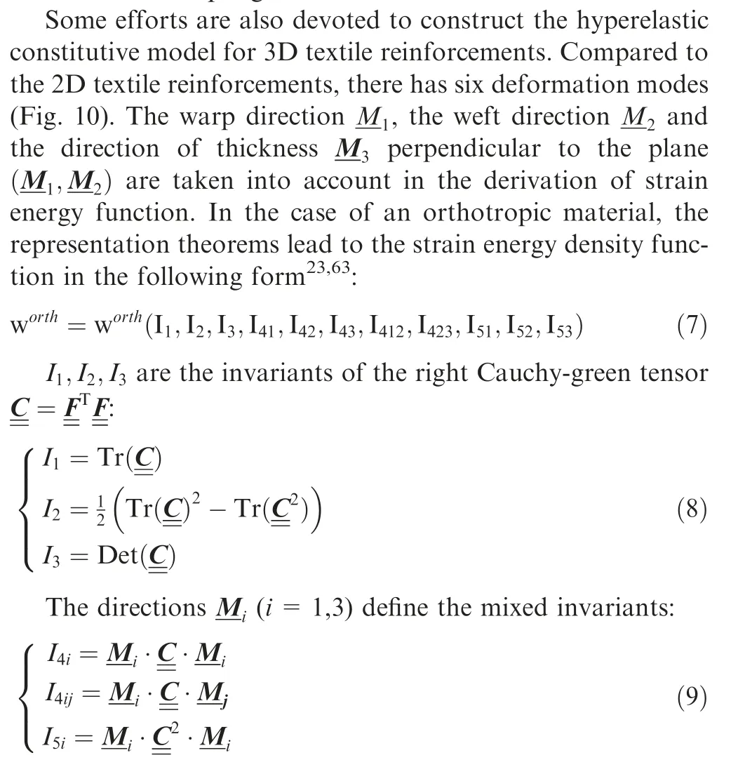

Fig. 10 3D woven reinforcement and six deformation modes.63
A so-called physical invariant is defined for each deformation mode (Fig. 10) by combining the invariants of Eqs. (9)and (10).23

Ielongα,Icomp,Icp, Ictα(α=1,2) are respectively the invariants denoting the elongation in the warp and weft directions, compaction in the thickness direction, in-plane shear and transverse shear in the warp and weft directions. These physical invariants define the strain energy potential. It is generally assumed that the contribution to the strain energy potential of each strain mode is independent. However, coupling between the different modes has been shown in Refs.58-62.Consequently, the strain energy density is the following form when assuming each strain mode is independent:
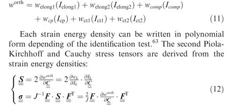
2.3.2.3. 3D solid element models considering the bending energy of fiber.The kinematic models used in 3D solid finite elements(e.g.,a hexahedra with 8 nodes)are standard continuous Cauchy models(i.e.,first gradient model).This is the case of hyperelastic models as presented above. For textile reinforcements,it has been shown that the bending stiffness of the fibers plays a significant role.63–65Therefore,it needs to consider the bending deformation energy of fibers. However, the standard continuous models are unable to take into account the local the stiffness of fibers. To address this issue, Mathieu et al.63proposed an improved modeling approach by including the additional curvature related internal loads in the 3D solid elements.From the position of the nodes of the neighboring elements of a hexahedron, a curvature of the fibers is calculated (Fig. 11).An independent bending stiffness is added from the non-linear constitutive law. The bending moment Mbendis calculated from the curvature χ:

2.3.3. Shell approaches for composite forming
As textile reinforcements are generally thin(small thickness),it is natural to model them by shells in general.The simplest methods(bar assembly then membrane)were used firstly,then shell approaches taking into account the bending of fibers were implemented. Due to the relative sliding of fibers, the bending stiffness of textile reinforcement is not directly related to its inplane tensile modulus as the classical continuous materials and its kinematics are specific compared to the conventional shell structure,leading to the difficulty in the analysis if still following the theories and methods used for the classical continuous materials.
2.3.3.1. Truss elements. Draping simulations based on simple truss elements have been proposed by Sharma and Sutcliffe65and Skords et al.66This approach is different from kinematic methods because the truss finite elements, although their behavior is very simplified,give a solution by solving the equations of mechanics. Fig. 12(a) shows a truss element model where diagonal bars provide plane shear stiffness.66The tension characteristic of these bars must be non-linear and possibly viscous to translate the plane shear behavior of the fabric.Fig. 12(b) displays a simulation of a hemispherical forming where the truss model can detect the wrinkle onset during the forming process.
2.3.3.2.Membrane elements.Given the low flexural stiffness of textile reinforcements in bending, some simulations use membrane approaches that neglect this bending stiffness.67–71In the plane of the membrane, the mechanical behavior is strongly dependent of the directions of the warp yarns and weft yarns. Constitutive models in large deformations sometimes called ‘non-orthogonal’ have been developed for this purpose.67,68,72The hypoelastic and hyperelastic models presented in previous sections can be used in a membrane approach.73,48,74The membrane approach has limitations that come from the importance of taking bending stiffness into account in certain situations and in particular when wrinkles develop or are likely to develop.74
2.3.3.3. Combined beam and membrane elements. The use of truss finite elements presented in Section 2.3.3.1 is a simple and effective way to describe the yarns of a woven reinforcement and to follow them during deformation. To describe in-plane shear stiffness a membrane element can be added to

Fig. 11 Schematic of 3D solid element models considering bending energy of fiber.63
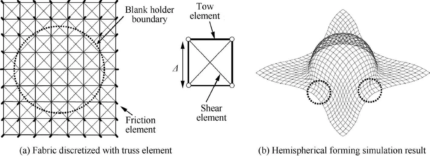
Fig. 12 Fabric draping modeling with truss element model.66
a set of four bars (Fig. 13). Simulations based on the association of truss elements in the direction of warp and weft yarns and membrane elements to describe the shear behavior have been proposed by Cherouat et al.75. Bending stiffness can be added by considering beams instead of trusses or shells rather than membranes.47,76–80These elements are effective and integrated naturally along the direction of the warp and weft yarns. The identification of the properties of the beams and membranes is nevertheless not necessarily simple. This approach is sometimes referred to as ’discrete elements’. Nevertheless, it is still a continuous modeling of the textile reinforcements on a macroscopic scale. There is no relative movement between yarns as the case in the mesoscopic approaches of the whole preform as shown in Refs. 26,80.
2.3.3.4. General shell elements. Shell finite elements are the most natural modeling for a composite textile reinforcement.They are thin, and their thickness is small compared to their dimension in the plane.Their geometry becomes curved during forming. Shell finite elements are a large and very active area of computational mechanics. The curvature associated with their thin geometry brings many difficulties in particular related to the locking.81–85Fibrous reinforcements bring serious difficulties within the framework of hull theories. Of course, it is necessary to take into account in the design, the direction-controlled membrane behavior of the fibers with high shear.For this purpose the hypoelastic and hyperelastic constitutive models presented in the Sections 2.3.2.1 and 2.3.2.2 can be used.The main difficulty in modeling textile shell reinforcements lies in the fact that the relationship between the bending and membrane stiffness given by classical theory (Mindlin,Kirchhoff) is not verified. Given the possible slip between the fibers, the bending stiffness of textile reinforcements is much lower than that given by classical shell theories. In this goal,some approaches proposed to decouple the membrane and bending stiffness of woven fabrics.86,87In particular, it is possible to consider textiles as a laminate with layers of different behavior (Fig. 14). It is thus possible to find characteristics of the laminate that ensure the right membrane and flexural stiffness. Another approach developed for example in Ref.25is to decrease the thickness of the shell and increase the Young’s modulus so that the flexural and tensile stiffness are checked.
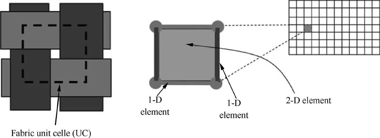
Fig. 13 Principle of modeling based on combination of beam and membrane elements.76
2.3.3.5. Stress resultant shell elements. A resultant stress approach naturally separates the membrane from the bending.Tensions T11and T22in the warp and weft fiber directions,the in-plane shear moment Msand the bending moments M11and M22.These stress resultants are the conjugates of axial elongation ε11,ε22, in-plane shear γ, and curvature χ11,χ22. In a RUC (Representative Unit Cell), L1and L2denote the length in the warp and weft fiber directions,the internal virtual work of tension,in-plane shear and bending take the following form:

For any virtual displacement field with a zero value on the boundary, δWextand δWaccdenote the external virtual work and the virtual work of acceleration,the virtual work theorem is written as:

The relationship between the stress resultant and the strains determines the mechanical behavior of the textile reinforcement using the experiments presented in Section 3. Eq. (14)written in a triangle made of woven RUC (Fig. 15) leads to the development of a stress resultant three node shell finite element implemented.88–90The approach accounts for membrane and bending stiffness independently.As specified before,this is necessary for fibrous reinforcements.This stress resultant shell approach has been shown to be effective in analyzing textile reinforcement forming91as well as for wrinkle analysis.74,92Fig.16 shows the simulation of a tetrahedral shape in comparison to the experimental shaping with this approach.
2.3.3.6. Superposition of shell and membrane elements. The independency of the membrane and bending behaviors can be obtained by the superposition of a membrane element and a pure bending element. For instance in Refs. 94,95, constitutive equations are implemented in a DKT(Discrete Kirchhoff Triangle) shell within Abaqus user-defined element with decoupling of membrane and bending stiffness(Fig.17).Good agreement with experiment was noted,which demonstrates the good predication capability of this type of shell element in the forming simulation.
2.3.3.7.Beyond standard shell theory:specific shell approach for fibrous shells. As discussed in the previous sections, most current shell elements are based on the Kirchhoff or Mindlin shell theory. In Kirchhoff shell theory, it is assumed that the shell normal after deformation remains perpendicular to the middle surface. However, this is not case for the thick fiber reinforcement.As shown in Fig.18(a)and 18(c),a significant transverse shearing deformation can be noted. Besides, according to the curvature definition in the Mindlin shell theory, curvature is defined as the first derivative of the rotation of the normal,which is not the case presented in Fig. 18(a) and (c), where there has no rotation for the normal vectors, but the corresponding curvature is not zero. Therefore, textile reinforcements do not verify Mindlin’s theory and it is not possible to simulate correctly the bending of thick textile reinforcement using Mindlin’s shell finite elements.
The bending of textile reinforcements is based on certain specific physic constraints: fibers are quasi-inextensible and there has slippage between fibers. To reflect these specific features, a specific shell finite element for thick textile reinforcements has been proposed by Liang et al.95. This element was based on the Ahmad’s approach, consisting of parallel fibers(Fig. 18(b)). The internal virtual work of the element is equal to the sum of the virtual work of tension and bending of each fiber. The bending stiffness is strongly related to the friction between fibers, and the influence of friction can be implicitly taken into account in the bending stiffness of each fiber. The curvatures and the axial strains in the fibers are calculated using adjacent elements. The curvature definition is consistent with its mathematic meaning. The results obtained with this specific woven shell element are in good agreement with experiment(Fig. 18(c)). More details are suggested to see Ref.95for this specific shell element.
2.3.4. Second-gradient material models

Fig. 14 Textile reinforcements seen as a laminate.86,87
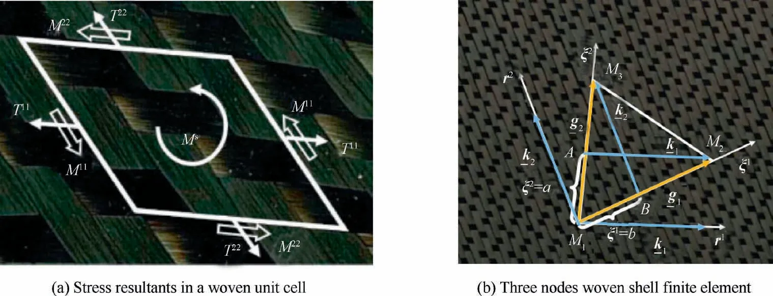
Fig. 15 Illustration of stress resultant shell element.
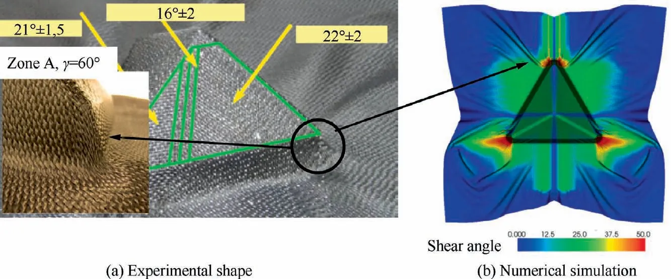
Fig. 16 Tetrahedron forming.74
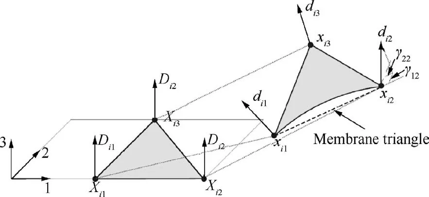
Fig. 17 DKT shell element kinematics for initial and deformed configuration.93
The second-gradient theory can be used to enhance the ability of the classical continuum mechanical theory by taking into account effects of material’s micro-structural. The displacement field needs to be complemented by introducing additional kinematical variables, which are called microstructural fields.The formulation of second-gradient theory is explained in detail in Ref.96,97. A model based on the second-gradient theory was proposed by Ferretti et al.98to simulate the deformation of fiber reinforcements. Bias extension test was used to demonstrate that the second-gradient theory is able to model the onset of internal shear boundary layers which can’t be predicted by a simple first gradient model. Based on the work of Ferretti, Madeo et al.99adopted it to model the deformation behavior of thick woven interlock.A three-point bending simulation highlighted the capacity of the second-gradient model to predict accurately the macroscopic bending deformation of thick woven interlock, in particular the rotations of crosssection. Barbagallo et al.100proposed a strain energy density function accounting for in-plane shear deformation, bending deformation and elongations in the warp and weft fiber directions within the fame of second gradient theory. This model was validated by a bias-extension test of unbalanced carbon interlocks. The specific macroscopic asymmetric S-shaped deformation was correctly captured in the bias-extension(Fig. 19). Latter they have extended their model to simulate the deep drawing of 3D woven fabrics.101Their results indicate the proposed second gradient model is able to give an accurate prediction of complex forming and it is less mesh dependent compared to the model based on the classic continuum mechanics.Boisse et al.102pointed out the classical continuum mechanics of Cauchy is insufficient to depict the deformation of 3D woven reinforcements, one possible solution is to supplement the potential by the second gradient terms.
3. Wrinkling simulation during forming of textile reinforcement
Wrinkling is one of the most serious defects that can occur during the forming of textile reinforcements. The low bending stiffness of textile reinforcement due to the possible slippage between the fibers makes such wrinkling frequent.The appearance, growth and the geometry of these wrinkles must be simulated in order to check that the useful part of the textile preform does not contain wrinkles. The ‘‘locking angle” is often used to determine the occurrence of wrinkling. It was shown that its use is questionable.74In-plane shear stiffness plays a role in determining the appearance of wrinkles, but other stiffness is also important.
3.1. Wrinkling of unidirectional materials
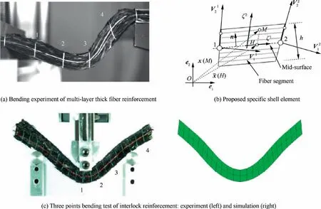
Fig. 18 Specific shell element for bending simulation of thick fibrous materials.95

Fig.19 Experimental shape of bias-extension test with 56 mm displacement(left)and deformed shape from simulation(right)based on the second gradient theory (red with black fibers). The blue curves represent the shape boundary of experiment shown in the left.100
Unidirectional reinforcements (UD) are not strictly textiles.Nevertheless they are made of continuous fibers like textile reinforcements and can be seen as a boundary of textile reinforcements.Moreover,wrinkling of UD reinforcements during autoclave consolidation is an important issue in the manufacture of composites,there have been many studies on this topic.The fibers of UD reinforcements and UD prepregs are noncrimp,which is good for stiffness.Different processes are used for the forming of UD prepregs: hand lay-up, automatic fiber placement (AFP) or automatic tape lay-up (ATL). They are usually consolidated under vacuum.103,104During forming,unidirectional laminates can give wrinkles.105–108Wrinkling of unidirectional reinforcements during forming and consolidation in an autoclave has been the subject of several studies.105–109Significant wrinkling may develop (Fig. 20). The wrinkling of UD laminates can occur globally when there has excess material due to forming and the resulting overall state of compression. In most cases, one (or some) layer(s) of the stack is subjected to compressive stress in the direction of the fibers,resulting in wrinkling of the layer and its neighbors.Fig. 21 shows the wrinkles that can develop when consolidating a thick UD stack because the compaction of the stack over a curved tool causes excess fiber length.108To model wrinkles onset in the consolidation process,Belnoue et al.110proposed a hyper-viscoelastic material model to simulate UD prepreg deformation.The potential energy was additively decomposed into an elastic part relating to the fiber deformation and viscous part controlling the flow of resin through the fiber network. With this constitutive model, Belnoue et al.108simulated the consolidation process of L shape sample as shown in Fig. 21. Wrinkles were correctly predicted, demonstrating the effectiveness of the proposed materials model.
3.2. Simulation of wrinkle development in woven reinforcement forming
The phenomenon of wrinkling is common in textile materials because possible slippage between the fibers leads to low bending stiffness. Wrinkling was experimentally analyzed in relation to in-plane shear.111–114These studies generally define a’’shear locking angle’’ from which wrinkles develop. This approach can be questioned according to Ref.74. Wrinkling simulations have been proposed from the elements presented in Section 2.3.3: truss elements,66membrane elements69,70or beam and shell elements.73,75,102In these simulations, hypoelastic or elastic-viscoplastic material model were employed to characterize the mechanical behavior of woven reinforcement.74,75,77

Fig. 20 Wrinkles during forming of UD prepreg.105,107
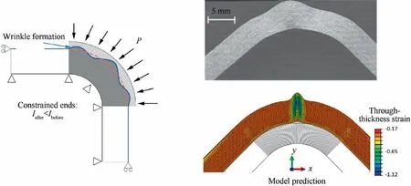
Fig. 21 Consolidation-Driven wrinkles generation in thick composite parts.108
To analyze the influence of the characteristics that condition wrinkling, draping simulations on a cylinder are performed in Fig. 22 using the finite shell element briefly presented in Section 2.3.3.5. In Fig. 22(a), in-plane shear and bending rigidities are neglected,only tensile stiffness is considered. There are no wrinkles in the deformed shape and the in plane shear is very large in the corners of the fabric. When in-plane shear rigidity is added, many small wrinkles appear(Fig. 22b). Taking into account all the rigidities in Eq. (14)(tension, in-plane shear and bending) leads to a realistic deformed shape. This test shows that the high tensile stiffness leads to the quasi-inextensibility of the fibers. In-plane shear stiffness can cause wrinkling when the shear angle is large.But the onset of wrinkles also depends on other terms in Eq.(14). Finally, bending stiffness define the shape of the wrinkles.74,115
3.3.Wrinkling during forming of multilayered textile composites
The simultaneous forming of a stack of textile plies is currently a difficulty in the forming of composite reinforcements.Several studies have shown that significant wrinkling develops when the stack has layers of different orientations. However, when the layers have the same orientation, forming can be performed without wrinkles (Fig. 23).116–119The analysis of this phenomenon by numerical simulations has shown that friction sliding,in the case of a different orientation of the layers,leads to zones where yarns are in compression in the fiber direction which causes wrinkling.116Non-linear elastic material model was used to characterize the mechanical behavior of textiles,coulomb friction model was applied to simulate the tool-toply and ply-to-ply friction. Three deformation modes were considered: tension, in-plane shearing and bending. When bending a multilayered textile reinforcement, wrinkles can develop depending on the boundary conditions (Fig. 24).Huang et al.120investigated the occurrence of these wrinkles by simulation with different boundary conditions.

Fig. 22 Influence of different rigidities on wrinkles simulation for textile reinforcement draping.116
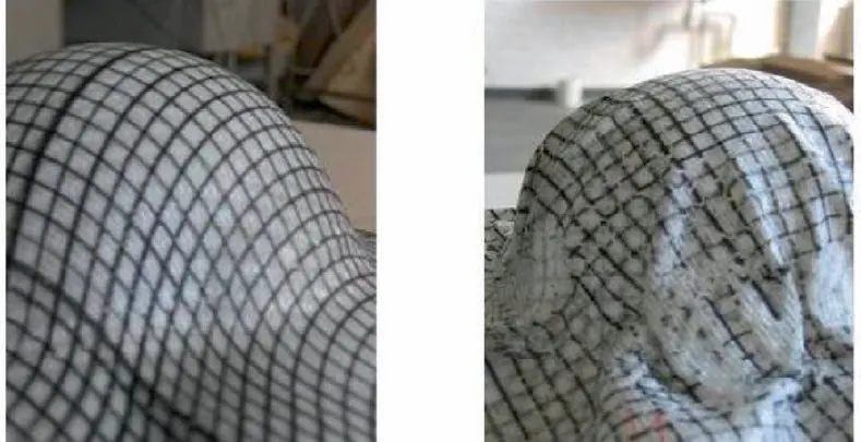
Fig.23 Forming of a laminate with a 0°relative orientation and a 45° relative orientation.118
4. Experimental material characterization methods for macroscopic modeling
Many efforts have been undertaken to characterize the mechanical behaviors of textile reinforcements during forming.In this section, only experimental characterization methods related to the macroscopic modeling would be presented in this review. The complexity and the types of tests that need to be conducted depend on the comprehensiveness of the model.The aim of these characterization tests is to understand the mechanical behaviors of textile reinforcements and identify the material parameters in the constitutive law. A review of the experimental characterization methods for textile reinforcements in forming has been conducted by Gereke et al.,121Bussetaa and Correia.122They have presented the various tests used to determine in-plane tension, in-plane shear, out-ofplane bending, tool-fabric/fabric-fabric friction and the fullfield strain measurements with digital image correlation(DIC). In this review paper, some new developed tests related to the thick reinforcements are presented.
4.1. In-plane tension
Yarn direction is the maximum tensile stiffness direction of textile reinforcement. Uniaxial tensile test is the classical method for measuring stiffness along yarn direction. Tensile behavior along yarn direction shows a strong non-linear in the initial stage of loading due to the undulations, particular for the multi-directional fibrous reinforcements (e.g., woven fabrics). To characterize the coupling between two yarn directions, biaxial tension is conducted by a device that is able to stretch in warp yarn direction (denoted as direction 11) and weft yarn direction (denoted as direction 22) simultaneously,as shown in Fig.25(a).This device is two hinged rhombus that imposes a biaxial strain state to a cross-shape of woven specimen.The imposed strains along two yarn directions are adjustable to prescribe different strain ratios. Load sensors placed behind the specimen give the load in each direction.The strain is measured by mechanical extensometers or optical method.123,24,124Fig. 25(b) shows biaxial tensile test results for a 2×2 twill carbon fabric with different stain ratios. The horizontal axis in Fig.25(b) denotes the strain in the 22 direction (weft yarn direction).
4.2. In-plane shearing
In-plane shear is the most dominant deformation mode for woven textile reinforcement in forming, involving yarn rigid rotation around the weave crossover point.The primary resistance of in-plane shear comes from the friction force between yarns.The in-plane shear characterization of woven reinforcements can be implemented by two widely used tests: pictureframe test and bias-extension test.
Picture-frame test has been widely used to characterize the in-plane shear behavior of woven textile reinforcements.Picture-frame is made of four bars of equal length. Four bars are hinged at each corner so that the initially square frame becomes a rhombus one when loaded by a tensile machine(Fig. 26). The sample size has an effect on the measured shear curve, therefore normalization of shear curve with sample size is necessary to make the test results comparable.125In pictureframe test,careful fabric handling and alignment is required in the clamping. A consequence of incorrect clamping the specimen is the possibility of introducing tensile fiber strains if fibers are misaligned with picture-frame edge,small deviations would cause large errors in the measured force due to the high fiber tensile stiffness.126,114,127The shear-tension coupling was investigated detailly by Harrison et al.128using specifically designed experimental device.
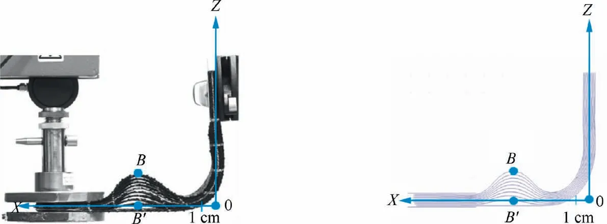
Fig. 24 L-Flange forming with wrinkling due to bending of a 10 layers stackings.120

Fig. 26 Picture-frame test device and shape of sample.
Bias-extension test is another commonly preferred method to characterize in-plane shear due to its relative simple test procedures and minimal equipment requirement. It is performed on a sample in which the warp and weft yarn directions initially are orientated at 45 degrees to the loading direction.Unlike picture-frame test, bias-extension test is less sensitive to the misalignment due to its free boundary conditions compared to picture-frame test.Specimens were cut into the shape as shown in Fig.27,which contains regions A,B,C and clamp area. Pure shear deformation is supposed in region A, and shear angle can be mathematically determined from the global displacement if there has no yarn slippage in the test.The main difficulty of this test is to accurately establish a relation between the shear angle and shear stress.126,127,129To rule out the possible influence of slippage, Cao et al.126recommended to use optical measurement methods for shear angle instead. Direct measurements of the shear angle using optical methods instead of calculating shear angle from the global displacement are becoming the common method in the in-plane shear test.130–132
In summary,no matter picture-frame test or bias-extension test, the measured shear curve is sensitive to yarn tension that is induced by the boundary conditions imposed by the device.Attention needs to be paid to the yarn slippage to rule out its impact on the calculation of shear angle based on the global displacement. Optical methods, such as DIC (Digital Image Correlation), should be used to determine the shear angle and check the homogeneity of the sample deformation to further validate the test results.
4.3. Transverse shearing
Transverse shearing is important especially for thick textile reinforcement in the modeling as it is one of the primary deformation modes in forming process. A specific device to characterize the transverse shear behavior of 3D interlock reinforcement was developed as shown in Fig.28.Two parallel plates were fixed to the sample and pure shear strain was imposed to the specimen, the transverse shear strain energy density function then was built based on the transverse shear strain.
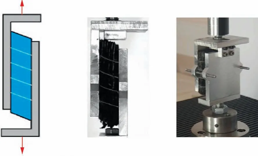
Fig. 28 Transverse shearing test device for thick interlock reinforcement.23
4.4. Transverse compaction
At the end of forming, textile reinforcements must be compacted to increase fiber volume fraction. An understanding of compressibility, typically in terms of compaction pressure versus fiber volume fraction, allowing required pressure to be determined for the desired fiber content.132Robitaille et al.133published an extensive review of both experimental methods and modeling approaches for dry reinforcement compaction.Q.T Nguyen et al.22investigated the compaction behavior of multi-layer textile reinforcements. Compaction procedures are relatively simple, with material compacted between two parallel platens by a tensile machine.Fig.29 shows the typical stress vs fiber volume fraction for a cyclic compaction and for different types of reinforcements. A non-linear and in-elastic deformation can be noted for the transverse compaction behavior of textile reinforcements.
Many works are also available for conducting compaction experiments of both thermoset and thermoplastic prepregs,applying a similar approach as the one used for dry textile reinforcements.134–139The purpose is to increase fiber volume fraction and decrease the void content. As prepregs have no clear paths for entrapped voids and resin to escape, high pressure generally is required to achieve the desired degree of compaction. As expected, this behavior is highly dependent on temperature and loading rate, with increasing time at pressure resulting in a reduction in void content to a limiting value.
4.5. Bending deformation
Due to the relative motion between fibers,bending stiffness of textile reinforcements is not directly related to its in-plane tensile modulus as the classical continuum materials. Although it is very weak (compared to its in-plane tensile stiffness), it is linked closely to the wrinkling appearance. Some available investigations have already demonstrated that if the bending stiffness is not accounted in the modeling, wrinkles cannot be predicted correctly in the forming process.74,115
Two standard tests are commonly used for evaluating fabric bending stiffness: the standard cantilever test and the Kawabata bending test. The standard cantilever test(Fig. 30) is based on the assumption of elastic linear bending behavior and enables determination of only one parameter:bending rigidity.It involves to push a rectangular strip of fabric on a horizontal board slowly forward until the tip of the strip touches a titled board with an inclined angle of 41.5° to the horizontal. Then bending stiffness is calculated based on the bending length following the empirical formula.141The standard cantilever test is simple, but it assumes the bending behavior is liner in the data processing. De Bilbao et al.142developed an improved horizontal cantilever test which is able to characterize the non-liner bending behavior of textile reinforcements. An optical camera was used to capture the deflection shape.Soteropoulos et al.143proposed a vertical cantilever bending test method by rotating the horizontal cantilever experiment 90°to measure the bending behavior of dry fabric.The main advantage of vertical cantilever bending compared to horizontal cantilever bending is that it can control the rate of applied load,but it is only valid for small bending deformation.Liang et al.115developed an improved cantilever bending test set-up which can work both for prepregs and textile reinforcement.Smooth curvature curve is important for the bending stiffness characterization. A piecewise quartic B-spline curve was used to fit the deflection curve and to calculate the curvature.144Smooth curvature can be obtained with this proposed method.
Kawabata bending test enables to record moment versus curvature during a bending loading cycle.145It records directly the evolution of bending moment versus curvature during a load-unload cycle. The sample was clamped between a fixed and movable clamp (Fig. 31(a)). During the test, the movable clamp rotates around the fixed clamp to impose a pure bending on the sample.Fig.31(b)shows a typical result carried out on a 2.5D carbon fabric in the weft yarn direction. A review on the bending test and simulation of textile reinforcement was made in Ref.146
4.6. Fabric-fabric/fabric-tool friction
In the forming process, friction exists between the textile reinforcements/prepregs and mold. Inter-ply friction strongly affects the forming quality, such as wrinkles. Many excellent works were carried out to investigate the friction behavior of tool/fabric with the pull-out experimental setup.147–150Reinforcements or prepregs were clamped between two heated pressure platens and were then pulled out. The influence of slip velocity,temperature and normal pressure on the tool-ply friction were investigated. Allaoui et al.151and Hivet et al.152developed a pull-out setup to measure tool-fabric, fabricfabric and yarn-yarn frictions (Fig. 32). They found the friction is sensitive to the relative fiber orientation of samples.Zhang et al.153conducted a similar work on the measurement of friction behavior of woven thermoset prepregs with the pullout test method. They have investigated the sliding velocity,the relative fiber orientations between two plies on the friction.Their findings of the influence of fiber orientations on the friction is consistent with the work of Allaoui and Hivet,151,152indicating the necessity to account for the influence of fiber orientation on the friction force in the modeling.
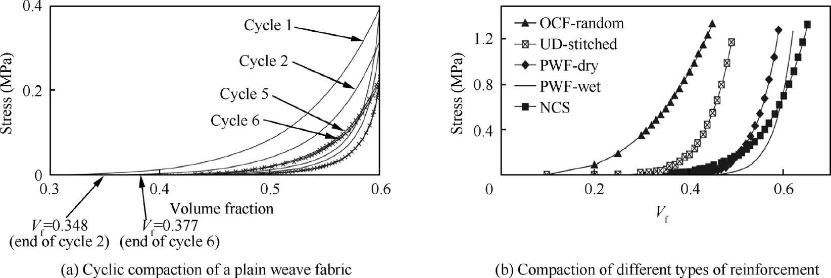
Fig. 29 Typical stress vs fiber volume fraction curves in transverse compaction test.134

Fig. 30 Standard cantilever bending test device.140
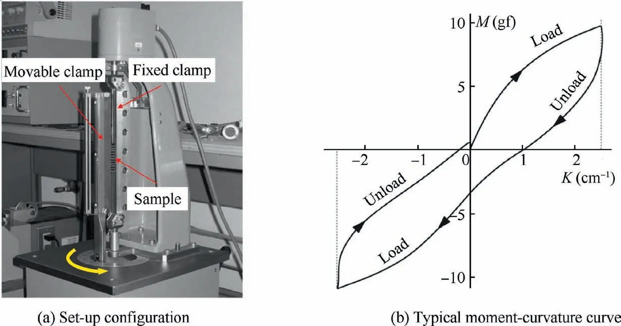
Fig. 31 Kawabata bending test.142

Fig. 32 Pull-out friction test for glass plain weave.152
5. Challenges
5.1. Mechanical characterization aspects
Although a lot of experimental methods and set-ups are developed to characterize the mechanical behaviors of fibrous materials,the primary issue is that they are user customized and not standard. For instance, several bending stiffness test methods are available for fibrous materials. However, as there has no unified specification for specimen dimension and operation procedure, test results are inclined to present large variation,leading to the material test data can’t be fully shared among different academic groups. Besides, most current material characterization methods are falling into the macroscale behavior characterization. Material behavior characterization at yarn scale or fiber scale is very few. One primary reason is their small dimension scale poses a high requirement for the experimental set-up. For instance, to investigate the fiber distribution inside the yarn when subjected to the external force,high resolution camera or micro-CT scan is generally indispensable.
In-situ test is another trend of fibrous material characterization, since it is able to give the evolution of material microstructure with respect to the applied load. Due to the resolution constraint, the dimension of specimen in the in-situ test(usually micrometers to millimeters),is generally much smaller compared to the one used in the traditional test,leading to the difficulty in the preparation of specimen.The specimen preparation is one of the primary challenges for the in-situ test of fibrous materials.
Moreover, some new forming methods are developed and applied for fibrous materials, incremental forming is the most representative one, in which cyclic loading and unloading are applied.Therefore,the hysteretic behavior of fibrous materials needs to be characterized. One challenge in this aspect is how to accurately characterize the potential hysteretic behavior coupling between the different deformation modes, such as the in-plane shearing and bending.
5.2. Modeling method aspects
For the time being, many of the methods used to simulate composite forming are based on the approaches that have been developed for more traditional materials, particularly metals.However, the physics of the deformation of textile reinforcements is fundamentally different. Currently, empirical and sometimes artificial modifications are used to simulate the deformation of the textile reinforcements. For example, the decoupling of membrane and bending stiffnesses allows simulations to be carried out, but it is also an indication that the standard shell theory used is not suitable for the fibrous materials.Simulation of textile reinforcement forming will be more effective if specific approaches have been developed.
Another issue that will need to be developed is the transverse compaction of the textile reinforcement. In processes,compaction of the textile reinforcement is frequent.For example in LCM processes, this compaction conditions the flow of the resin into the reinforcement. Likewise, the thermoforming of thermoplastic prepregs requires a stage of consolidation of the stacks at the end of the process to avoid porosities. Significant progress has been made in the development of solid-shell elements that need to be adapted to the deformation modes of composite reinforcements.
6. Conclusions
This paper was motivated by the fact that numerical simulations play a key role in driving the advancement of composite parts manufacturing technologies and low-cost application of composite materials. An extensive overview of computational and experimental methods was given for the forming of textile composite reinforcements. Simulation approaches and models related to the microscopic,mesoscopic and macroscopic scales were presented.
In microscale, fiber generally needs to be explicitly modeled,and although the microscopic modeling approaches allow to investigate the inter-fiber slippage and fiber movement within yarn, giving realistic description of yarn deformation,the primary issue currently is the high computation cost brought by the large number of elements and contact pairs,confining its application only in a small scale of textile reinforcements (usually in a single RVE). How to accelerate the solution speed is one of the primary challenges facing in the microscopic modeling.In mesoscale,yarn was taken as continuous materials and adapted constitutive models were proposed to model yarn’s specific mechanical behavior. Yarn geometry has significant impact on the prediction accuracy. Direct yarn geometry construction from CT- scan is the most popular method. The primary challenge is to develop high automatic and robust image processing algorithm for fibrous materials with high fiber volume fraction.
Macroscale models are mostly used both in academy and industry. Mechanical characterization methods relating to macroscale models were presented. In-plane shear tests are the most developed, in particular the picture frame test and the bias-extension tests. Biaxial tensile, transverse compaction and bending tests showed that they were also necessary.Hyperelastic, hypoelastic and viscoelastic models specific to textile reinforcements have been developed. Bending deformation simulation models of textile reinforcement were presented.Due to the fibrous nature, these models are outside the scope of standard plate or shell models.
Wrinkling is the most typical defect in composites forming process,the appearance and the geometry of wrinkles must be simulated in order to check that the useful part of the textile preform free of them. Progresses have been made, but it is not sufficient, more in-depth studies are in great demand.Besides, the concurrent multiscale forming modeling strategy,such as combined meso-macro modeling, would be the hot topic in the next years.
Declaration of Competing Interest
The authors declare that they have no known competing financial interests or personal relationships that could have appeared to influence the work reported in this paper.
Acknowledgements
The author Biao Liang appreciates the funding support from the Young Fund of Natural Science Foundation of Shaanxi province, China (No. 2020JQ-121) and Fundamental Research Funds for the Central Universities,China(No.31020190502002).
 CHINESE JOURNAL OF AERONAUTICS2021年8期
- CHINESE JOURNAL OF AERONAUTICS的其它文章
- A novel virtual material layer model for predicting natural frequencies of composite bolted joints
- Multi-layered plate finite element models with node-dependent kinematics for smart structures with piezoelectric components
- Modeling bending behavior of shape memory alloy wire-reinforced composites: Semi-analytical model and finite element analysis
- Sequential ensemble optimization based on general surrogate model prediction variance and its application on engine acceleration schedule design
- Transition prediction and sensitivity analysis for a natural laminar flow wing glove flight experiment
- Modeling on mechanical behavior and damage evolution of single-lap bolted composite interference-fit joints under thermal effects
