Effect of beam current on microstructures and mechanical properties of joints of TZM/30CrMnSiA by electron beam welding
Ting WANG, Bin YU, Yifan WANG, Siyuan JIANG
a State Key Laboratory of Advanced Welding and Joining, Harbin Institute of Technology at Weihai, Weihai 264209, China
b Shandong Provincial Key Laboratory of Special Welding Technology, Harbin Institute of Technology at Weihai, Weihai 264209, China
KEYWORDS 30CrMnSiA;Electron beam welding;Mechanical properties;Microstructure;TZM alloy
Abstract Electron beam welding experiments of TZM alloy and 30CrMnSiA steel butt joints were carried out with different beam currents. Microstructures and chemical compositions of typical zones were analyzed by optical microscopy, scanning electron microscopy and X-ray diffraction.The mechanical properties of the joints were evaluated by tensile strength tests.Besides,nanoindentation tests were carried out to compare the brittleness of the reaction layer and other typical microstructures. The results illustrated that the reaction layer at the interface between fusion zone(FZ)and TZM alloy was the weak position of the joint,which was divided into Fe2Mo layer and a mixture layer of Fe2Mo and α-Fe phases.As the beam current increased,the thickness of the Fe2Mo layer decreased,which resulted in the increasing of the tensile strength of the joints.When the beam current exceeded 24 mA,the formation of the joint was poor with a low tensile strength.When the beam current was 24 mA, the joint presented the highest strength of 191.3 MPa and the joint fractured along the Fe2Mo layer near the TZM alloy side with a brittle fracture mode.
1. Introduction
With the continuous development of science and technology,there are higher demands for the comprehensive performance of various engineering components. A single metal structure is usually difficult to meet the needs of industrial production while a composite structure joined by dissimilar materials can take full advantage of different materials to achieve structural and functional integration of components.Therefore,the welding of dissimilar metals has attracted the attention of more and more researchers.1–6TZM alloy, as one of the most promising molybdenum alloys, has been widely used in aeronautic, nuclear power and other industrial fields in view of its good high-temperature performance, excellent thermal and electrical conductivity, outstanding thermal shock resistance and high wear and corrosion resistance.7–10As widely known, steels play important parts in the construction and manufacturing industries because of their relatively low prices and reliable performances. Among them, the 30CrMnSiA medium carbon hardened tempered steel has excellent strength and toughness, which is widely applied in the fields of aircraft manufacturing and aerospace.11,12The welded joint of TZM alloy and 30CrMnSiA steel will have an unexceptionable application prospect in aeronautics and space industries.
In recent years, researchers have studied the joining of molybdenum alloys with other metals,but there are few investigations on the joining between molybdenum alloys and steels.On the one hand,the physical and chemical properties of these two metals are quite different,and on the other hand,there are a variety of brittle intermetallic compounds formed during the welding process. Basuki and Aktaa.13investigated the diffusion joining between tungsten and EUROFER97 steel with V as an intermediate layer, which effectively reduced the formation of carbides. Wang et al.14studied the brazing of Mo-Cu alloy and Cr18-Ni8 stainless steel with Ag-Cu filler metal.When the temperature reached 940°C and the holding time was 20 min, a reliable joint without brittle intermetallic could be obtained, which shear strength was 125 MPa.Ambroziak15investigated the optimizing parameters for friction welding of TZM alloy to other metals. Zhou et al.16investigated the cracking mechanism of joints by utilizing laser welding of dissimilar metals Mo and Ta. The results showed that Mo/Ta joints had a strong tendency to crack during the solidification process, and the lower ductility of the fusion zone would increase the possibility of cracking.
Compared with other methods, electron beam welding has unique advantages in dissimilar metal joining, such as high energy density, vacuum protective atmosphere and controllable welding parameters.17–19Chen et al.20studied the electron beam welding of tantalum and stainless steel. When the electron beam was deflected to stainless steel by 0.2 mm, an excellent joint could be obtained. Electron beam welding of 321 austenitic stainless steel and refractory niobium alloy were investigated by Ali and Homam.21A sound welded joint could be achieved when the beam focused on the interface of two base metals and microdilution of Nb was less than 60%.Electron beam welding between pure molybdenum and Kovar alloys were investigated by Chen et al.22The research studied the effects of beam deflection on the microstructure and defect creation respectively.When the electron deflection was 0.6 mm to Kovar alloy side, the weld was composed of equiaxed crystals without cracks appearing on the Mo side, and the tensile strength of the joint was increased to 260 MPa.
As is known, beam deflection is usually used to control the energy distribution in the electron beam welding of dissimilar metals.23–25However, researchers rarely pay attention to the effect of welding heat input on the microstructure and performance of the joint.26In this paper, TZM alloy and 30CrMnSiA steel were joined by electron beam welding with a beam offset by 0.2 mm. The welding speed was controlled to 400 mm/min, and the weld heat input was changed by changing beam currents. The appearance and microstructure of the weld, the interfacial microstructure and phase composition, tensile strength and the characteristics of the fracture of the joints were analyzed.
2. Experimental procedure
2.1. Materials
In this paper,the base metals were 30CrMnSiA steel and TZM plates which were produced by using powder metallurgy and hot rolling process as shown in Fig. 1. They have obvious hot rolling characteristics with elongated grains. Their chemical compositions were listed in Table 1 and Table 2. Table 3 showed their primary physical and chemical properties.
2.2. Welding procedure
The steel plate and TZM plate were cut into 50 mm×25 mm×3.3 mm by wire-cut electric discharge machine. Prior to welding, the specimens were sanded with abrasive papers and then cleaned with acetone by ultrasonic cleaner for 10–15 min. The welding process was conductedby TDW-7 electron beam welding apparatus under the vacuum degree of 4×10⁻²Pa. Welding parameters are listed in Table 4. It should be noted that the beam offset was the distance of the beam deflection to steel as shown in Fig. 2.

Table 1 Chemical composition of TZM (wt%).
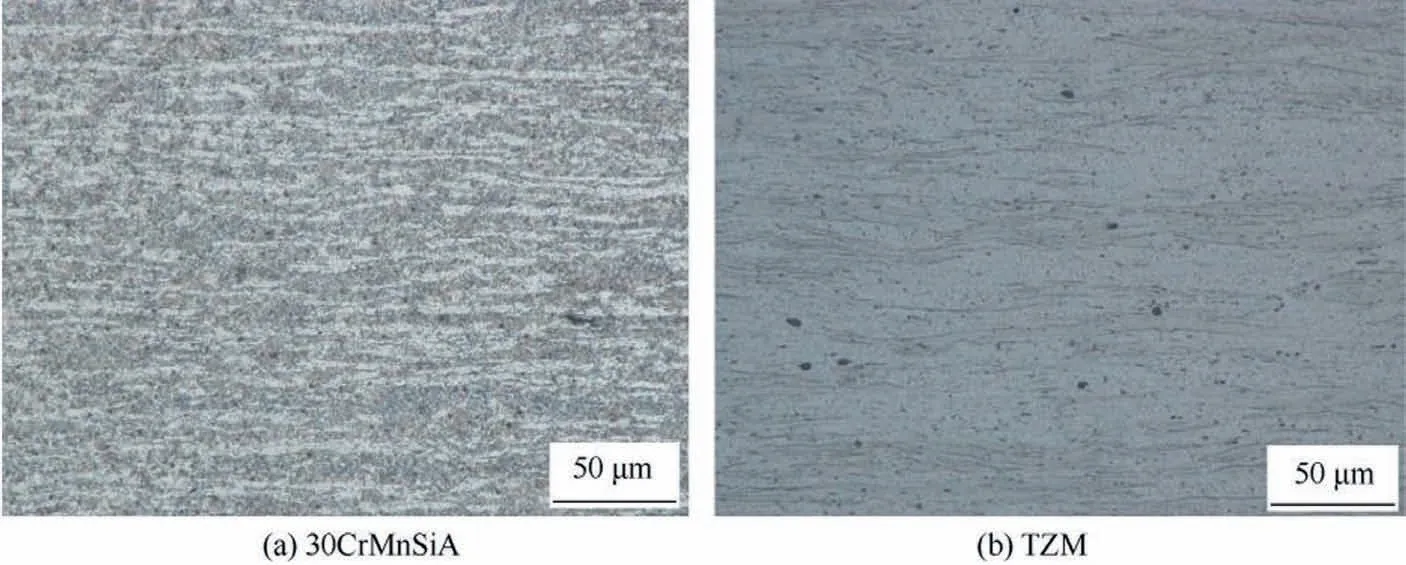
Fig. 1 Microstructures of base metals.

Table 2 Chemical composition of 30CrMnSiA (wt%).

Table 3 Primary physical and chemical properties of base metals.
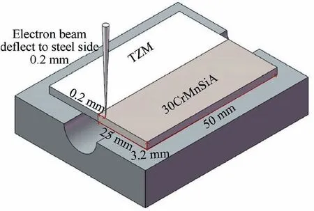
Fig. 2 Schematic illustration of EBW process.
2.3. Microstructure characterization and mechanical properties tests
The typical microstructures of electron beam welded TZM/30CrMnSiA joints were observed by optics microscopy(OLYMPUS DSX-510).Fracture surfaces and TZM/FZ interfaces of joints were detected by electron scanning microscopy(Hitachi S-4700). Furthermore, in order to determine the phases and chemical compositions on tensile fractures and cross-sections of the joints, An X-ray diffraction scan (XRD)and energy dispersive spectrometer (EDS) were performed.The metallographic specimens were polished with diamond polish and etched about 6–8 s with steel etching reagent (5 gram FeCL3, 10 mL HCL, 100 mL H2O) firstly, then etched about 6–10 s with TZM etching reagent (HNO3:H2SO4:H2O=5:3:3). The tensile test was conducted on the INSTRON-5967 universal testing machine at a constant displacement velocity of 1 mm/min at room temperature, and the dimension of the specimen used for the tensile test was shown in Fig. 3. Nanoindentation Tester (Anton Paar NHT2)was used to test the mechanical properties of the intermetallic compounds layers. The corresponding load was 20 mN and the dwelling time was 10 s.
3. Results and discussion
3.1. Surface appearance and macrostructures of cross-sections
The influences of beam current on the microstructures of the joints were investigated with a 0.2 mm deflection to steel,and the top surface morphologies are shown in Fig. 4. The Sample 1 and 2 joints welded with lower beam currents were indicated poor appearances with weld reinforcement. As the beam current increased, the Sample 3 and 4 were depicted excellent appearances with small surface concavity.The centerline of the weld is shifted to the steel side. This is because the melting point of steel is significantly lower than that of TZM alloy and the position of the electron beam spot is deflected to steel by 0.2 mm.
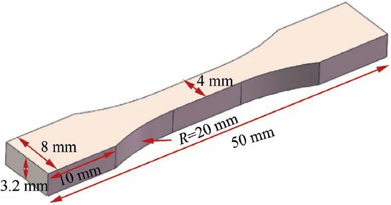
Fig. 3 Dimension of specimen used for tensile test.

Table 4 Electron beam welding parameters of TZM/30CrMnSiA joints.
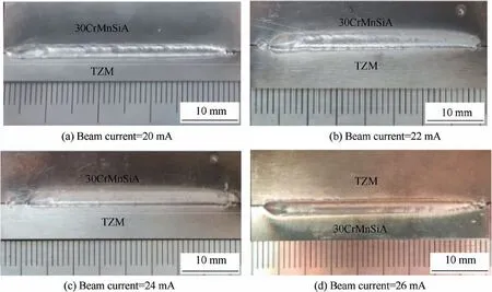
Fig. 4 Top surface morphologies of welded joints with different beam currents.
Fig. 5 shows the cross-sections of the joints with different beam currents. The amount of steel melted in the FZ was larger than that of TZM alloy.The fusion line on the TZM alloy side was almost straight and only a small amount of the base metal was melted at the upper part of the weld pool.The steel side was depicted as funnel shape attributed to their melting point difference and the beam deflection. As a result, the cross-section showed the joint had a typical electron beam welding-brazing characteristic. Meanwhile, the width of the upper FZ increased distinctly with the increasing beam currents, as illustrated in Fig. 6. Closer observation found that the round black impurities in the weld were pores, resulting from the residual gas in the TZM alloy. The density of pores could be calculated by counting the number of pores on the cross-sections. Fig. 5(a) depicted the joint was not fully penetrated when the beam current was 20 mA. There were a mass of pores in the FZ and microcracks appeared along the TZM fusion line.When the beam current was 24 mA,the joint was penetrated completely,there was only one pore appearing on the cross-section, so the density of pores decreased distinctly compared with Sample 1.As beam current increased,the residence time of the melting pool was prolonged, and resulted in escaping of residual gas from the molten pool. A defect-free joint was obtained when the beam current was 24 mA. However, when the beam current exceeded 24 mA, a large amount of TZM alloy melted into the upper FZ, and there were some pores that appeared along the upper fusion line of the TZM side, as shown in Fig. 5(d).
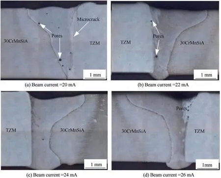
Fig. 5 Cross sections of electron beam welded joints with different beam currents.
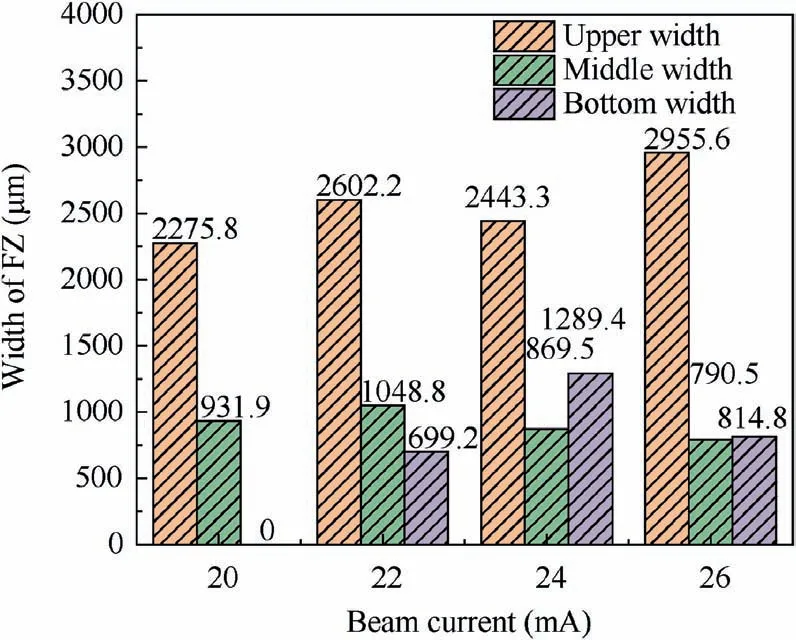
Fig. 6 Widths of FZs in joints with different beam currents.
3.2. Typical microstructures of the joints
The typical microstructures of the joint (Sample 3) are shown in Fig.7.A significant reaction layer appeared at the interface of FZ and TZM alloy as shown in Fig. 7(a), which was the result of a metallurgical reaction between molybdenum alloy and steel. Fig. 7(b) exhibits that the center of the FZ is composed of equiaxed grains with average grain sizes (diameter)of 11.53 μm, and only a small number of columnar crystals formed near the two fusion lines, which the aspect ratio was about 4.07. The microstructure of the heat affected zone(HAZ)on the steel side is characterized by acicular martensite as shown in the Fig. 7(c). In order to determine the key point on the mechanical properties of the joints,further analysis was conducted on the interface of the FZ and TZM alloy.
3.3. Microstructures of TZM/FZ interfaces of joints
Fig. 8 exhibits the interfacial microstructures and line scan results of the joints with different beam currents.On the whole,the thicknesses of reaction layers decreased with the increasing of beam currents.The interfacial reaction layer of all the samples was divided into layer Ⅰand layer Ⅱaccording to the characteristics of the microstructure. The layer Ⅰexhibited bright white single-phase microstructure,which was distributed along the TZM alloy fusion line, and grew to the layer Ⅱ. As for Sample 1, there was a small amount of unmelted TZM alloy in the layer Ⅰ. Similarly, as the beam currents increased, the thickness of the layer Ⅰdecreased.The layer Ⅱwas mainly composed of two phases,bright white phase A and dark grey phase B. The content of Fe and Mo elements were quite different between phase A and phase B.When the beam current was less than 22 mA, the distribution of the two phases in the reaction layer Ⅱwere irregularly, which resulted in the line scan curves of Mo and Fe elements fluctuated greatly. The content of Fe element went down and the Mo element went up at the region of phase A, while it was opposite at the region of phase B, as shown in Fig. 8(b), (d). In contrast, when the beam current exceeded 22 mA, the distribution of the two phases were continuous and uniform in the layer Ⅱ,which were consistent with the distribution of Mo and Fe elements as the line scan results exhibited in Fig. 8(f) and (h).
The compositions of different phases were analyzed by EDS in spot mode,which were denoted by points 1–12 respectively in Fig. 8. Based on the Fe-Mo binary phase diagram as shown in Fig. 9, the potential phases are deduced as listed in Table 5. The bright white phase A in layer Ⅰwas Fe2Mo compound,and the layer Ⅱwas composed by a mixture of Fe2Mo and α-Fe. The result of XRD on the interface as shown in Fig. 10, which confirmed the existence of the above phases.From Fe-Mo binary phase diagram, it can be seen that the Fe2Mo phase was formed according to the peritectoid reaction at 950°C. The enthalpy of formation of Fe2Mo phase was-14.1 kJ/mol at 298 K,27which was much higher than that of other phases in the binary phase diagram. As a result, Fe2-Mo phase nucleated and grew firstly during the solidification of the molten pool. It was stable around the stoichiometric composition when the temperature was below 950°C,and this phenomenon was reported by related published literatures.28,29The thermal conductivity of TZM was much higher than 30CrMnSiA steel, so the temperature of the TZM fusion line was lowest among the entire molten pool. Fe2Mo phase grew perpendicular to the fusion line of TZM alloy in the direction of the temperature descent.As the beam current increased,the high-temperature residence time of the melting pool was prolonged,which was not conducive for the nucleation of the Fe2-Mo phase, resulting in the thickness of the Fe2Mo layer decreased. As the element line scan results of the four joints shown, the content of Mo element was less than 30at% when it diffused to the layer Ⅱ, and Fe2Mo phase and α-Fe phase grew together in this zone. From all the above results, beam currents affected the interfacial microstructures,phase compositions and elements distributions significantly by controlling the melting ratios of the base metals.

Fig. 7 Typical microstructure of welded joint in Sample 3.
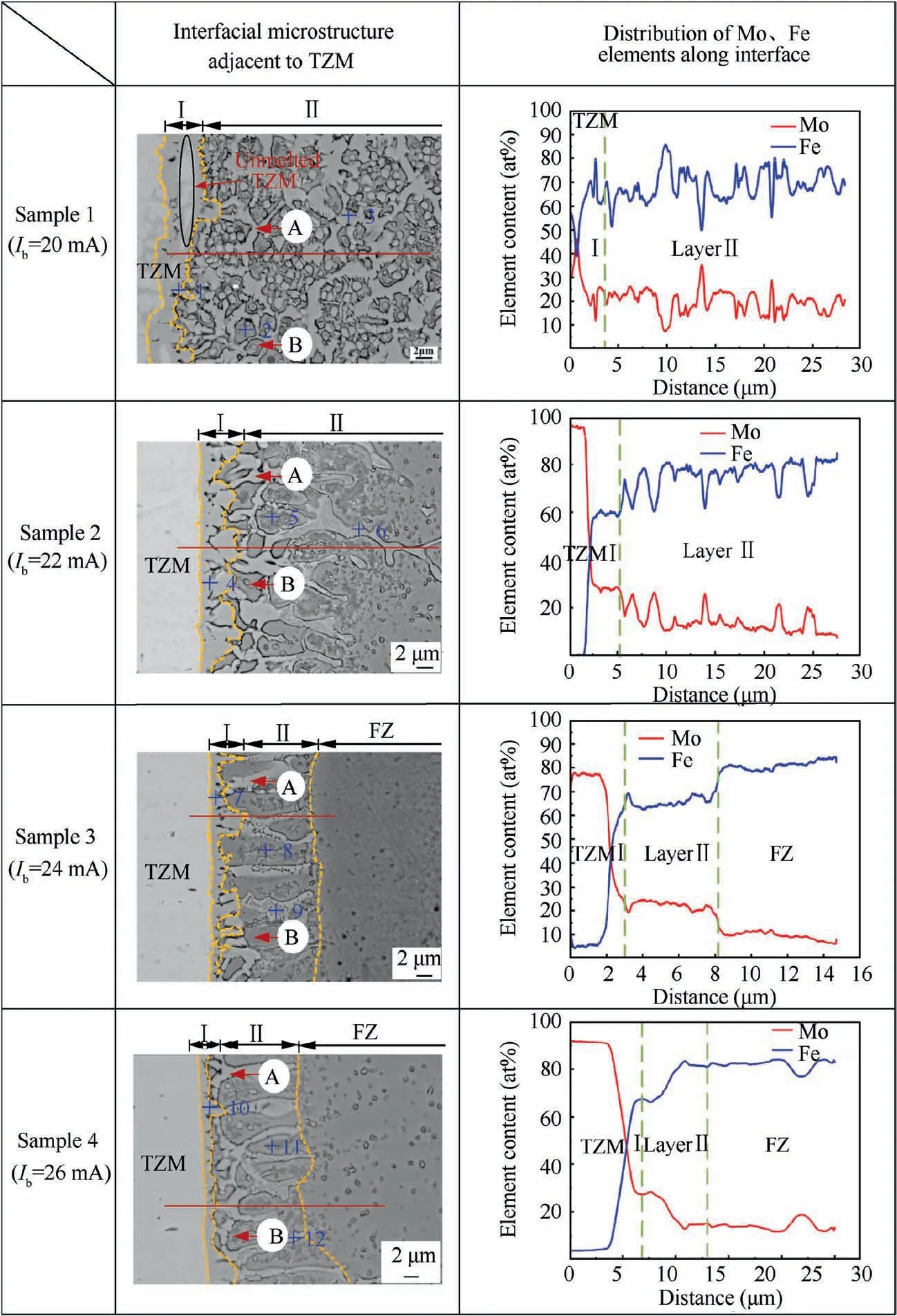
Fig. 8 Interfacial microstructures and line scan results of joints with different beam currents.
3.4. Mechanical properties and fracture surface morphologies
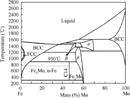
Fig. 9 Fe-Mo binary phase diagram.30

Table 5 Chemical compositions of different phases at interface.
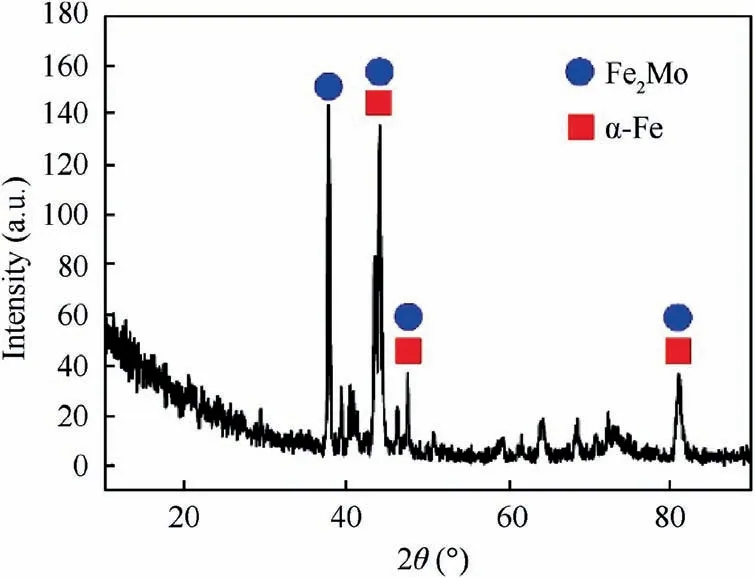
Fig. 10 XRD results of reaction layer.
Nanoindentation tests were carried out on the reaction layer and other typical microstructures of the joint of the Sample 3, in order to analyze the effect of Fe2Mo intermetallic compound on the mechanical property of the joint. Fig. 11 illustrated the load-depth curves of different indentation positions as marked in the magnified SEM microstructure diagrams.Spot A was loaded on the reaction layer Ⅰcomposed of Fe2Mo phase.Spot B was loaded on the α-Fe phase in reaction layer Ⅱ.Spot C was loaded on TZM alloy base metal and Spot D was loaded on the α-Fe in the fusion zone. When the load was 20 mN, the maximum depths of indentations of spots A,B, C and D were 284.35 nm, 378.97 nm, 446.28 nm, and 516.54 nm respectively as illustrated in Fig. 11. Furthermore,the nano-indentation hardness was 14168 MPa, 7322.6 MPa,5169.3 MPa and 3832.3 MPa separately. It can be seen from the results that the hardness of Fe2Mo intermetallic compound formed by the metallurgical reaction between TZM alloy and steel was much higher than that of the TZM base metal and the FZ, so the reaction layer Ⅰwould deteriorate the mechanical properties of the joints.
In order to investigate the joining mechanism between TZM alloy and 30CrMnSiA steel, the tensile tests of all samples were conducted at room temperature.As the beam current increased, the tensile strength of the joints went up first and then went down, as shown in Fig. 12. When the beam current was 20 mA, the joint was lack of penetration, and the tensile strength was only 19.8 MPa. When the beam current was increased to 24 mA, the joint reached the maximum value of 194.3 MPa. But the beam current continued to increase, the tensile strength of the joint decreased with the poor formation and defects of the weld.
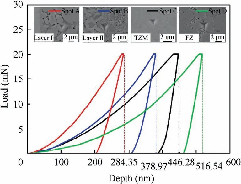
Fig. 11 Load-depth curves of different indentation positions.
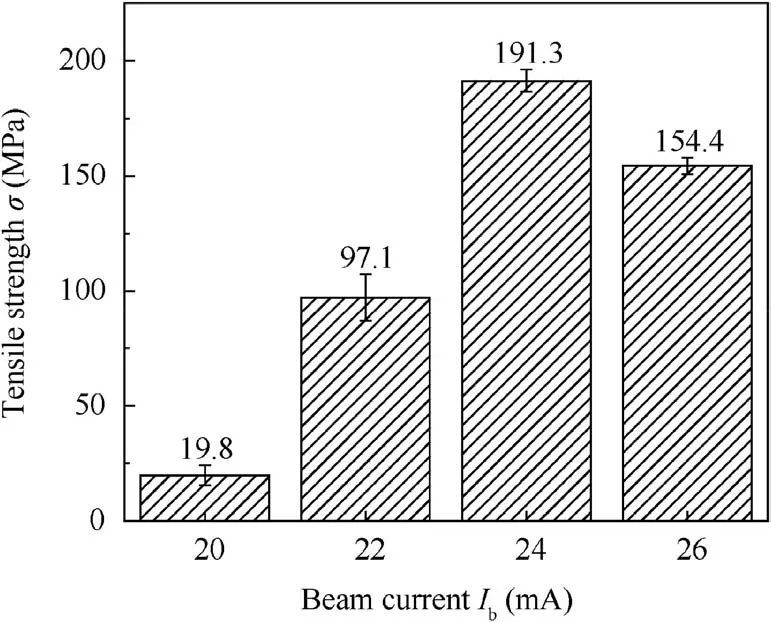
Fig. 12 Load-depth curves of different indentation positions.
Fig.13 shows the fracture splicing optical diagram and tensile fracture morphologies in SEM. Table 6 presents the EDS results of phases compositions on the fracture surface. The joints of all samples fractured along the layer Ⅰnear the TZM alloy side as shown in Fig.13(a),Fig.13(b)and(c)were fracture surface morphologies of steel side and TZM alloy side of sample 3 respectively. The fracture surface on the steel side was relatively flat, which presented a brittle fracture mode.There were a large amount of bright white phase on the fracture surface of the TZM side, which was the Fe2Mo phase detected by the EDS. Combined the interfacial microstructure of TZM alloy and FZ with the results of nanoindentation tests,it could be found that the fracture occurred along the Fe2Mo reaction layer, which was the key point on the mechanical properties of the joints.
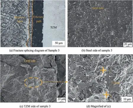
Fig. 13 Fracture splicing optical diagram and SEM morphologies of tensile fracture.

Table 6 EDS results of fractured surface morphology.
4. Conclusions
In this paper, the microstructures and tensile properties of the electron beam welded TZM/30CrMnSiA joints with different beam currents were investigated in detail.The primary conclusions were summarized as follows:
(1) TZM alloy and 30CrMnSiA steel were joined successfully by electron beam welding with beam deflection to steel by 0.2 mm.The optimal welding parameters(beam current: 24 mA, welding speed: 400 mm/min, beam offset: 0.2 mm) were obtained.
(2) The metallurgical reaction between TZM alloy and steel resulted in the formation of a significant reaction layer at the interface of FZ and TZM alloy, which was the weak position of the joint. The reaction layer was divided into layer Ⅰcomposed of Fe2Mo phase and layerⅡcomposed of Fe2Mo and α-Fe phases. As the beam currents increased,the thickness of the layer Ⅰdecreased.(3) Nanoindentation tests exhibited that the hardness of the Fe2Mo intermetallic compound was much higher than that of the TZM base metal and the fusion zone. As the beam current increasing, the tensile strength of the joints increased with the thickness of the Fe2Mo layer decreased.When the beam current was 24 mA,the joint presented the highest strength of 191.3 MPa and the joint fractured along the layer Ⅰnear the TZM alloy side with a brittle fracture mode.
Declaration of Competing Interest
The authors declare that they have no known competing financial interests or personal relationships that could have appeared to influence the work reported in this paper.
Acknowledgements
This project was supported by Shandong Provincial Key Research and Development Program of China (No.2019JZZY010439) and International Science & Technology Cooperation Program of China (No. 2011DFR50760).
 CHINESE JOURNAL OF AERONAUTICS2021年8期
- CHINESE JOURNAL OF AERONAUTICS的其它文章
- A novel virtual material layer model for predicting natural frequencies of composite bolted joints
- Multi-layered plate finite element models with node-dependent kinematics for smart structures with piezoelectric components
- Modeling bending behavior of shape memory alloy wire-reinforced composites: Semi-analytical model and finite element analysis
- Sequential ensemble optimization based on general surrogate model prediction variance and its application on engine acceleration schedule design
- Transition prediction and sensitivity analysis for a natural laminar flow wing glove flight experiment
- Modeling on mechanical behavior and damage evolution of single-lap bolted composite interference-fit joints under thermal effects
