Stress-controlled LCF experiments and ratcheting behaviour simulation of a nickel-based single crystal superalloy with [001] orientation
Bin ZHANG, Rongqio WANG,b, Dinyin HU,b,c,*, Kngh JIANG,Jinxing MAO,b,c, Fuli JING, Xinyi HAO
a School of Energy, Power Engineering, Beihang University, Beijing 100083, China
b Beijing Key Laboratory of Aero-Engine Structure and Strength, Beijing 100083, China
c Research Institute of Aero-Engine, Beihang University, Beijing 100083, China
d Hunan Aviation Powerplant Research Institute, Aero Engine (Group) Corporation of China, Zhuzhou 412002, China
e Aero Engine Academy of China, Aero Engine (Group) Corporation of China, Beijing 101304, China
KEYWORDS Crystal plasticity constitutive model;Low cycle fatigue;Nickel-based single crystal superalloy;Ratcheting behaviour;Stress-controlled experiment
Abstract Uniaxial ratcheting behaviour and low cycle fatigue(LCF)failure mechanism of nickelbased single crystal superalloy DD6 with [001] orientation are investigated through the stresscontrolled LCF tests with stress ratio of -1. Then the deformation behaviour during the wholelifetime from the beginning of the experiment to the fracture of the specimen,as well as the fractographic/metallographic morphology, are compared with the strain-controlled LCF experimental results.Through the scanning electron microscope(SEM) observations,it is shown that the failure characteristics under stress-controlled LCF loading are similar with those under strain-controlled loading.Nevertheless,unlike strain-controlled LCF loading,even under fully reversed cycle loading for stress-controlled LCF, DD6 shows significant ratcheting behaviour due to the tensioncompression asymmetry.In addition,the LCF lifetimes under stress control are significantly shorter than the LCF lifetimes under strain control,and the culprit might be the detrimental effect of ratcheting strain on LCF lifetime.Based on these phenomena,an improved crystal plasticity constitutive model on the basis of slip-based Walker constitutive model is developed through modifying the kinematic hardening rule in order to overcome the inaccurate prediction of decelerating stage and stable stage of ratcheting behaviour.Furthermore,combining the continuum damage mechanics, a damage-coupled crystal plasticity constitutive model is proposed to reflect the damage behaviour of DD6 and the accelerating stage of ratcheting behaviour. The simulation results for the stress-controlled LCF deformation behaviour including the whole-lifetime ratcheting behaviour show good agreement with the experimental data.
1. Introduction
Due to excellent high-temperature mechanical properties,nickel-based single crystal superalloys are widely used for turbine blades in aero-engines.1–3The turbine blades are subjected to cyclic centrifugal force resulted from repeated operations,such as start-up, thrust alteration and shut-down.4,5and thus LCF failure at high temperature often occurs. According to the article entitled General Principles for Fatigue Testing of Metals, reported in 1964, fatigue of materials is defined as ‘‘a term which applies to changes in properties which can occur in a metallic material due to the repeated application of stresses or strains, although usually this term applies specially to those changes which lead to cracking or failure”.6,7Studies on polycrystalline materials have indicated that LCF lifetimes under stress-controlled loading are generally significantly lower than LCF lifetimes under strain-controlled loading due to the greater LCF damage caused by the higher accumulated plastic deformation.8–10However, different from polycrystalline materials,nickel-based single crystal superalloy without grain boundary reveals anisotropic mechanical behaviour.Consequently, the LCF behaviour of nickel-based single crystal superalloys under stress-controlled loading requires further investigation and discussion.
Besides the typical cyclic deformation behaviour which is similar to the LCF deformation behaviour under strain control,the stress-controlled LCF deformation behaviour is often accompanied by ratcheting behavior.8–11When ratcheting behaviour occurs,in spite of a little increase of plastic deformation at each cycle,the accumulated plastic deformation with the increase of the number of cycles cannot be ignored, and this phenomenon could lead to the size excess or even failure of the structures.Generally,ratcheting behaviour is closely related to the loading conditions such as mean stress,12–14stress amplitude,13,15loading rate16and loading history.13,17–18Many researchers19–22have demonstrated that the deformation behaviour and mechanical property of metal material are obviously dependent on temperature and material as well as treatment process.14,23–27However, most of the studies are focused on polycrystalline material’s ratcheting behaviour.The ratcheting behaviour for single crystal superalloy needs to be investigated through conducting primary experiments and establishing simulation approach.
In terms of ratcheting behaviour simulation, since ratcheting is a secondary inelastic strain accumulation proceeding cycle by cycle,it is not easy to accurately simulate using traditional constitutive models.28To this end, many researchers improved the plastic or viscoplastic constitutive models through modifying the kinematic hardening rule.29–32Although these developed constitutive models get some achievements in the simulation of ratcheting curves, these models show deficiency in describing the micro-deformation mechanism such as the phenomenon of slip in the deformation process of the nickel-based single crystal superalloy. To solve this problem,crystal plasticity constitutive model is then established by introducing kinematic hardening rule like Armstrong-Frederick (A-F) equation in meso-scale.33–35Considering the excessive prediction of ratcheting when using crystal plasticity constitutive model with kinematic hardening rule similar to A-F equation,a few researchers36–42proposed some modified methods to provide a better prediction. To simulate the ratcheting behaviour accurately,the emphasis of the above models is to modify the rules of kinematic hardening,while the damage behaviour associated with deformation of materials is neglected. In fact, real stress varies with the accumulation of damage, which may result in the change of deformation behaviour. Therefore, it is necessary to introduce damage into the crystal plasticity constitutive model when simulating ratcheting behaviour.
In this regard,the present study focuses on investigating the stress-controlled LCF failure mechanisms and uniaxial ratcheting behaviour of nickel-based single crystal superalloy DD6 with [001] orientation. This paper is constructed as follows: Firstly, stress-controlled LCF experiments of DD6 with[001] orientation are performed at 980 ℃; secondly, the LCF failure mechanisms are investigated based on the fractographic and metallographic observation;thirdly,the features of straincontrolled deformation behaviour and fractographic/metallographic morphology are compared with the LCF experimental results under strain control; finally, an improved damagecoupled crystal plasticity constitutive model is developed,and the deformation behaviour including ratcheting behaviour is simulated.
2. Experimental details
2.1. Material and specimen
The material investigated in this paper is a nickel-based single crystal superalloy named DD6. The main chemical composition (in wt%) and the mechanical properties in [001] direction at 980 ℃are listed in Table 1 and Table 243.The round bars of DD6 deviate from the[001]orientation within 10 degree.All of the round bars are subjected to heat treatment under general conditions: 1290 ℃× 1 h+1300 ℃× 2 h+1315 ℃× 4 h/AC+1120 ℃× 4 h/AC+870 ℃× 32 h/AC (AC means air cooling).The microstructure of DD6 consists of γ′precipitates and γ matrix, and the cuboidal ordered L12-structured γ′precipitates embed coherently in the γ matrix of face-centered cubic structure (see Fig. 1).
The hollow tubular specimens used in the experiments are shown in Fig.2. All of the specimens have a 28 mm long gage section with an outside diameter of 12.0 mm and an inside diameter of 9.0 mm.
2.2. Procedures of LCF experiment
The LCF tests are conducted under stress control with a triangular waveform. The mechanical load and temperature load are imposed by a servo-hydraulic testing machine with±50 kN capacity and a 30 kW high frequency induction heater with induction coil. The mechanical strain is measured by a high temperature axial extensometer, and three K-type thermocouples are utilized to measure the temperature at the upper,middle and lower cross-section of the gage section respectively.The axial temperature deviation of the gage section is within±5°C.The relative locations of extensometer,thermocouples and specimen are shown in Fig.3.The LCF experimental conditions are listed in Table 3.
3. Experimental results
3.1. Fractography and metallography
Fig. 4(a)–(c)shows the fractographic features of the specimen after stress-controlled LCF tests. There are multiple crack sources at the surface of the specimen (see green arrows in Fig.4(a)and(b)).Similar fractographic features are observed at strain-controlled LCF experiments.44After crack initiation process, the cracks propagate to the inside of the specimen,and typical fatigue striations are formed under the LCF loading (see Fig. 4 (c)). The fatigue striation closest to the crack source is at the location of the red dotted line,and the distance between the red dotted line and the crack source in Fig.4(c)is about 370 μm.The metallographic features of the longitudinal section of the fractured specimen are plotted in Fig. 4(d)–(f).The samples for the SEM observations are corroded with 5 g CuSO4+25 mL HCl+20 mL H2O+5 mL H2SO4for 10 s.As shown in Fig.4(d),all of the cracks initiate at the surface and propagate to the inside of the specimen perpendicularly to the load direction (see orange arrows), which is consistent with the fractographic observations. At a higher magnification,it is found that the surface and tip of the cracks are obviously oxidized(see Fig.4(e)).In addition,a number of slip bands on octahedral slip systems <110> {111} are observed from Fig. 4 (f) (see red arrows), meaning that the octahedral slip systems <110> {111} are activated during the tests.Further, by comparing the observed γ/γ′microstructures of the failure specimens shown in Fig. 5 with the initial microstructure in Fig. 1, differences in γ/γ′microstructures are revealed before and after the stress-controlled LCF experiments. Firstly, the γ/γ′microstructures in both longitudinal cross-section and transverse cross-section do not maintain their regular square shape any more. Secondly, γ′precipitates have a trend of interconnection without a preferred orienta-tion. This phenomenon indicates that the morphology change of γ′precipitates occurs under stress-controlled LCF loading,also similar to the strain-controlled LCF tests45.

Table 1 Main chemical composition of DD6 (wt%).

Table 2 Mechanical properties of DD6 in[001]orientation at 980 ℃.
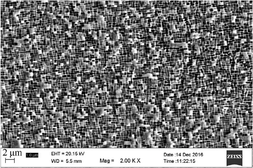
Fig. 1 Initial microstructure SEM image of DD6.
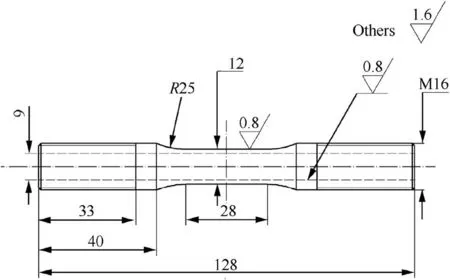
Fig. 2 Hollow tubular specimens (unit: mm).
Both fractographic and metallographic features observed under SEM are closely related to LCF damage.However,typical creep damage features,such as square-like cleavage planes with micro-voids or rafted structures, are not observed from SEM analysis, which indicates that almost no creep occurs in LCF experiment with stress ratio of -1.
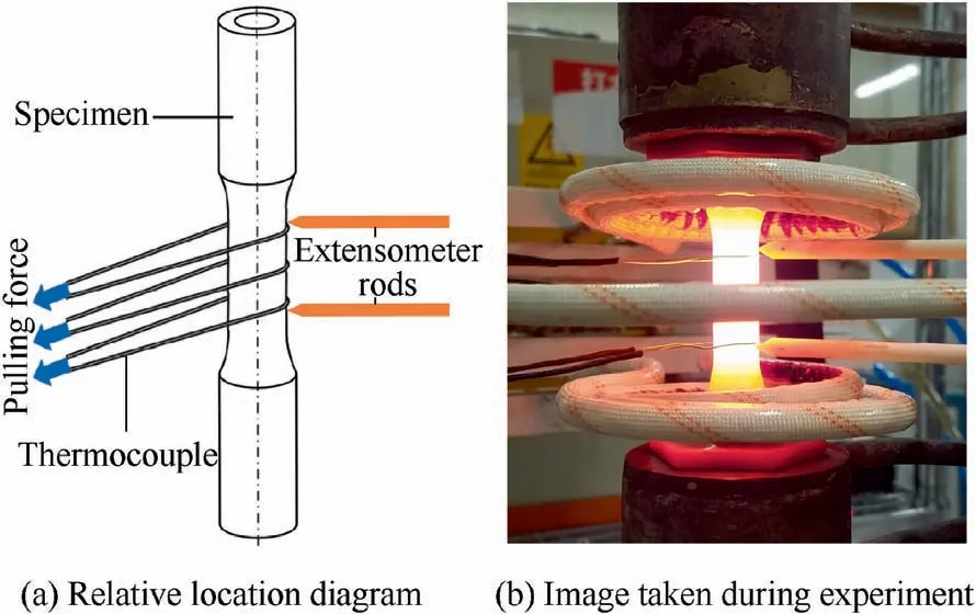
Fig. 3 Relative location of extensometer, thermocouples and specimen.
3.2. Deformation behaviour during whole lifetime period
The hysteresis loops of DD6 superalloy at first cycle, 0.2Nfcycle, 0.4Nfcycle, 0.6Nfcycle and 0.8Nfcycle are shown in Fig.6(Nfmeans the LCF lifetime).The width of the hysteresis loop increases with the increase of the stress amplitude.Moreover, obvious tension-compression asymmetry and ratcheting behaviour are revealed even if the average stress is zero.From the evolution of maximum strain and minimum strain during the stress-controlled LCF tests in Fig. 7, few changes for the strain amplitude are observed with the increasing number of cycles,which means no obvious cycle hardening or cyclic softening behaviour for the DD6 superalloy. Generally, the axial ratcheting strain εris defined as46–48

where εmaxand εminare maximum strain and minimum strain in a cycle, respectively. The increase of stress amplitude at the same average stress results in the increase of initial ratcheting strain rate as shown in Fig. 7. When the stress amplitude equals 300 MPa, there is insignificant ratcheting behaviour during the whole-lifetime process from the beginning to the fracture (see Fig. 7 (a)). Similar trend is found when the number of cycles is greater than 300 cycles at the stress amplitude of 400 MPa, meaning a shakedown stage of ratcheting behaviour for the material at this time (see Fig. 7 (b)). However,when the stress amplitude increases to 500 MPa, the wholelifetime ratcheting strain increases continuously, while the ratcheting strain rate is basically constant (see Fig. 7 (c)).

Table 3 LCF experimental conditions.
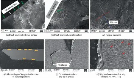
Fig. 4 Fractographic and metallographic features of failure specimens under stress-controlled LCF loading.
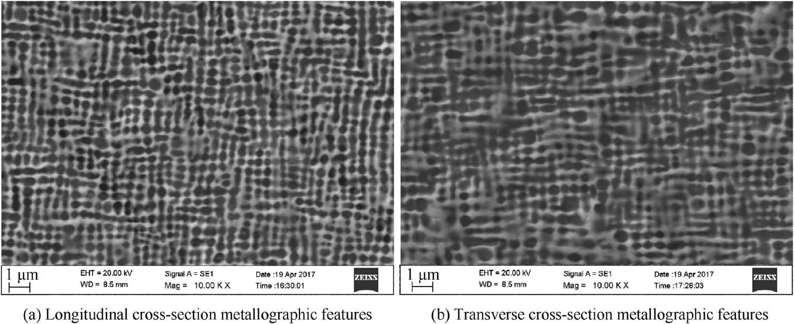
Fig. 5 Metallographic features of failure specimens at high magnification.

Fig. 6 LCF hysteresis loops at the first cycle, 0.2Nf cycle, 0.4Nf cycle, 0.6Nf cycle and 0.8Nf cycle.

Fig. 7 Evolution of maximum strain, ratcheting strain and minimum strain for stress-controlled LCF experiments.
Generally, ratcheting behaviour occurs under asymmetric stress cyclic load due to the accumulated plastic deformation.Since creep does not occur in LCF experiment with stress ratio of-1 according to the SEM observations in Section 3,the tension–compression asymmetry(see Fig.6)of nickel-based single crystal superalloy would lead to the accumulated plastic deformation and thus the ratcheting behaviour even though the LCF experiments are conducted under fully reversed cycle loading in this paper.
The strain-controlled LCF experiments on the nickel-based single crystal superalloy DD6 with [001] orientation at 980°C illustrated the whole-lifetime LCF deformation behaviour as shown in Fig. 849. In this condition, there is significant tension–compression asymmetry of nickel-based single crystal superalloy DD6 with [001] orientation under fully reversed cycle fatigue loading. However no obvious ratcheting behaviour is found under strain-controlled LCF loading.The cyclic response of peak stress generally reveals cycle hardening or cyclic softening at the initial stage, then the maximum stress and minimum stress remain stable, which is different from the deformation behaviour under the stress control.

Fig. 8 Strain-controlled LCF deformation behaviours at 980 ℃.49
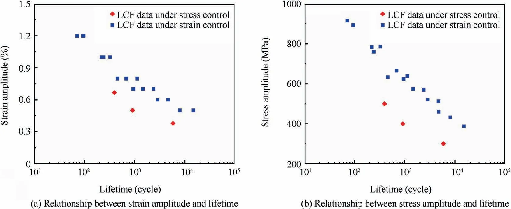
Fig. 9 Comparison of LCF lifetimes under different control modes.
It is well known that, for strain-controlled LCF experiments,the relationship between total strain amplitude and lifetime can be given directly. Although the maximum strain and the minimum strain change continuously during the stresscontrolled LCF experiments,the total strain amplitude is basically stable (see Fig. 7). Therefore, for strain-controlled LCF experiments and stress-controlled LCF experiments, the relationship between total strain amplitude and LCF lifetime is unique (see Fig. 9 (a)). In addition, the stress amplitude tends to be stable after a certain number of cycles in straincontrolled LCF experiments(see Fig.8(b)and(c)),and therefore there is unique stable stress amplitude for specific experimental conditions. Considering that the relationship between stress amplitude and stress-controlled lifetime is also unique,the relationship of stress amplitude-lifetime for both straincontrolled LCF experiments and stress-controlled LCF experiments can be given (see Fig. 9 (b)). Comparing the LCF lifetimes under two kinds of control modes (the data of LCF lifetimes under the strain control is obtained from Ref.43),we find that both stress-controlled and strain-controlled LCF lifetimes decrease with the increase of stress/strain amplitude.In addition, the LCF lifetimes under strain control are always longer than those under stress control whether in the relationship of strain amplitude-lifetime or the relationship of stress amplitude-lifetime. Previous studies have shown that the decrease in the lifetime is caused by the generation of ratcheting strain for the stress-controlled LCF experiments8–10.
4. Damage-coupled crystal plasticity constitutive model
The aforementioned experimental results reveal obvious ratcheting behaviour which is harmful to the lifetime under uniaxial stress loading. Thus it is essential to develop an appropriate and reliable constitutive model to predict the ratcheting behaviour of the nickel-based single crystal superalloy. The crystal plasticity constitutive model employed for the simulation of LCF ratcheting behaviour in this paper is on the basis of the slip-based Walker constitutive model which has been used in many nickel-based single crystal superalloys, such as PWA1480, Hastelloy-X and DD636,50–52. For traditional slipbased Walker constitutive model, the total strain εtis composed of elastic strain εeand inelastic strain εin, i.e.,

where the elastic strain can be obtained on the basis of the Hooke’s law. In general, for the nickel-based single crystal superalloys,only 12 octahedral slip systems are activated when the uniaxial load is applied along [001] orientation, and then the inelastic strain is governed as

where moand noare the vector of slip direction and the normal vector of the slip plane,respectively. And the shear strain rate on the rth octahedral slip system (˙γor) is formulated as
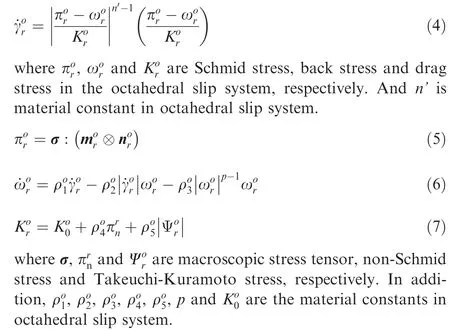
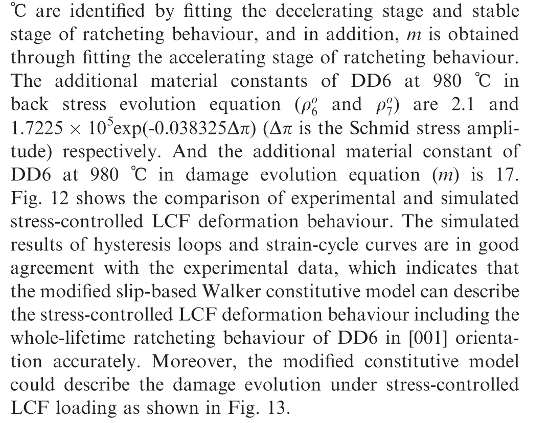
It is worth mentioning that the first term, second term and third term in Eq.(6)reflect strain hardening,dynamic recovery and thermal recovery, respectively. According to previous study, the ratcheting is generally overestimated due to the excessive prediction of dynamic recovery41,which is consistent with our simulation results(see Fig.10).In order to predict the ratcheting behaviour accurately, the back stress evolution equation is improved in this study based on the modified approach in Ref.42:

According to the continuum damage mechanics, the mechanical properties of materials or structures would deteriorate irreversibly during the experiments due to the damage such as growth of micro-voids or propagation of microcracks. Significant damage behaviour in the stress-controlled LCF experiments is observed in this paper (see Fig. 4 (d)).Thus taking the influence of damage evolution in the stresscontrolled LCF experiments into account, the Schmid stress is expressed as
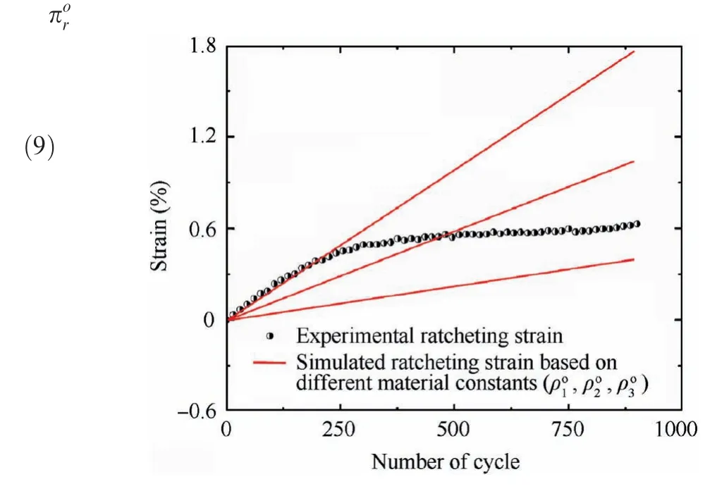
Fig. 10 Simulated ratcheting strain based on traditional slipbased Walker model with Eq. (6).
where D is a scalar of damage.In this paper,the classical LCF damage model proposed by Lemaitre53is used.When the average stress is zero, Lemaitre damage model is expressed as

where m, β and M are the temperature-dependent material constants, and Δσ is stress amplitude. It is worth mentioning that Eq.(10)is valid only for the stress ratio of-1.Integrating Eq. (10) by assuming the conditions of D=0 at N=0 and D=1 at N=Nf, we can obtain Nfthrough

Integrating Eq.(10)by assuming the conditions of D=0 at N=0 and D=Dn(damage when the number of cycles is n)at N=n (the number of cycles), we can express the relationship between Dnand n as
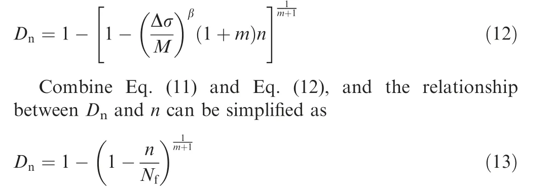
According to Eq. (13), when the LCF lifetime is obtained,there is only one material constant m in the relationship between Dnand n. Physically, D is caused by the microcracks (see Fig. 4 (d)), and 1-D indicates the ratio of effective bearing area to initial bearing area. The schematic diagram of effective bearing area in tension and compression stages of LCF experiments under stress ratio of -1 is shown in Fig. 11 (the green arrows indicate load direction). After the crack initiation, the effective bearing area (see blue arrows)in tension stage is obviously smaller than the initial bearing area,while the effective bearing area is consistent with the initial bearing area in compression stage. In view of this, we assume that the influence of damage on Schmid stress only plays a role in the tensile stage of a cycle.
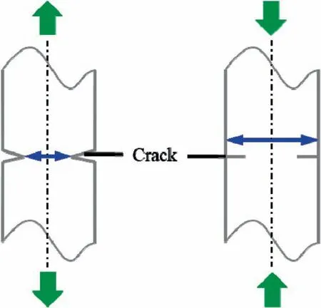
Fig. 11 Schematic diagram of effective bearing area in tension and compression stages of LCF experiments under stress ratio of -1.
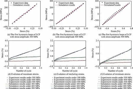
Fig. 12 Experimental and simulated stress-controlled LCF deformation behaviour.
5. Deformation behaviour simulation
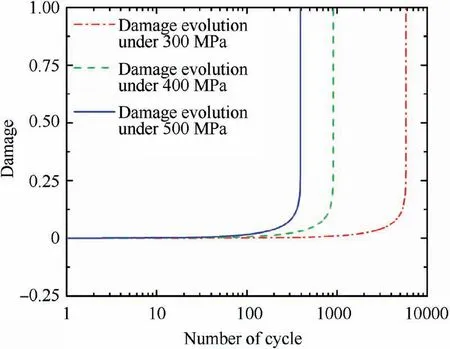
Fig. 13 Simulated LCF damage evolution.
6. Conclusions
This paper investigated the failure mechanisms and deformation behaviour of nickel-based single crystal superalloy DD6 under fully reversed stress-controlled LCF loading at 980°C.After comparing the LCF experimental results under strain control,a damage-coupled crystal plasticity constitutive model is proposed to simulate the stress-controlled LCF deformation behaviour including the whole-lifetime ratcheting behaviour.The main conclusions are drawn as follows:
(1) Both fractographic and metallographic analyses indicate that the cracks initiate at the specimen’s surface and then propagate to the inside of the specimen. In addition, the slip occurs on the octahedral slip systems<110> {111}, and the morphology of γ′precipitates changes during the stress-controlled LCF experimental process. The observations indicate that the LCF failure features under stress control mode are similar to those under strain control mode.
(2) A phenomenon different from the deformation behaviour in strain-controlled LCF experiment is found throughout the whole stress-controlled LCF experiments, i.e., no obvious cycle hardening or cyclic softening behaviour. In addition, the ratcheting behaviour occurs in stress-controlled LCF tests even under fully reversed cycle loading, which might result from the tension–compression asymmetry of DD6. When the stress amplitude is low, there is a shakedown stage in the ratcheting strain curve. However, when the stress amplitude increases to a certain value, the ratcheting strain increases continuously. The LCF lifetimes under stress control are shorter than those under strain control.
(3) The back stress evolution equation of traditional slipbased Walker constitutive model is modified by combining the deformation behaviour of DD6 under stresscontrolled LCF loading. Meanwhile, damage evolution’s influence is taken into account. Based on this,an improved damage-coupled crystal plasticity constitutive model is then developed. The simulation results of stress-controlled LCF deformation behaviour including the hysteresis loop and the whole-lifetime ratcheting behaviour show good agreement with the experimental data.
Declaration of Competing Interest
The authors declare that they have no known competing financial interests or personal relationships that could have appeared to influence the work reported in this paper.
Acknowledgment
We acknowledge the financial support from National Natural Science Foundation of China (Nos. 51875020, 51675024 and 51811540406), National Science and Technology Major Project (No. 2017-IV-0004-0041), Aviation Science Foundation of China (No. 6141B090314) and Academic Excellence Foundation of BUAA for PhD Students.
 CHINESE JOURNAL OF AERONAUTICS2021年8期
- CHINESE JOURNAL OF AERONAUTICS的其它文章
- A novel virtual material layer model for predicting natural frequencies of composite bolted joints
- Multi-layered plate finite element models with node-dependent kinematics for smart structures with piezoelectric components
- Modeling bending behavior of shape memory alloy wire-reinforced composites: Semi-analytical model and finite element analysis
- Sequential ensemble optimization based on general surrogate model prediction variance and its application on engine acceleration schedule design
- Transition prediction and sensitivity analysis for a natural laminar flow wing glove flight experiment
- Modeling on mechanical behavior and damage evolution of single-lap bolted composite interference-fit joints under thermal effects
