Design and analysis of truss deployable antenna mechanism based on a novel symmetric hexagonal profile division method
Jinwei GUO,Yongsheng ZHAO,b,Yundou XU,b,*,Yongjie LI,Jinto YAO,b
a Parallel Robot and Mechatronic System Laboratory of Hebei Province, Yanshan University, Qinhuangdao 066004, China
b Key Laboratory of Advanced Forging & Stamping Technology and Science of Ministry of National Education, Yanshan University, Qinhuangdao 066004, China
KEYWORDS Mobility;Modular mechanism;Profile division;Screw theory;Truss deployable antenna
Abstract As the deployment, supporting, and stability mechanisms of satellite antennas, spacedeployable mechanisms play a key role in the field of aerospace.In order to design truss deployable antenna supporting mechanisms with large folding rate,high accuracy,easy deployment and strong stability,aiming at the geometric division of the parabolic reflector,a novel method based on symmetric hexagonal division and its corresponding modular truss deployable antenna mechanism is proposed, and the original method based on asymmetric triangular division and its corresponding mechanisms are presented for comparative analysis.Then,the screw theory is employed to analyze the mobility of different mechanisms. Furthermore, the improved three-dimensional mesh method is used to divide the reflector surface of a large parabolic antenna designed by the two different methods,and the profile accuracy and the type of links are taken as the evaluation indexes to quantitatively analyze the division results.Finally,a three-dimensional model of the modular deployable mechanism based on the symmetric hexagonal design is developed,and the deployable mechanisms with different configurations based on the two design methods are compared and analyzed from the mechanical perspective. The research results provide a good theoretical reference for the design of deployable truss antenna mechanisms and their application in the aerospace field.
1. Introduction
Deployable structures have the ability to transform and can be predictably deployed in a controlled and secure manner by using multiple predetermined configurations and motion through known paths. These features bring benefits including high material efficiency, modularity, and maximum use of energy when considering requirements such as convenient transportation, installation, and overall structural sustainability.1–7The application of space-deployable antennas in the field of aerospace has made outstanding contribution to the aerospace industry. The requirements of high efficiency and accuracy in space exploration are a great challenge to improve the performance of existing space equipment and investigate new mechanisms.
The space-deployable mechanism is the supporting mechanism of space-deployable antennas. At present, spacedeployable antennas in orbit mainly include truss deployable antennas,8–12peripheral truss deployable antennas,13–18and radial rib deployable antennas.19Truss deployable antennas have been widely used in the aerospace field due to their advantages of high storage ratio, high accuracy, and good deployment stability. The truss system of truss deployable antennas is composed of some basic units.In 1969,NASA proposed the earliest concept of paraboloid truss antenna in the report ‘‘Feasibility study of large space erectable antennas”.20By changing the size and number of modules, an antenna can be adapted to the requirements of different apertures. The basic units of truss deployable antennas are tetrahedron,9,12,21pyramid,22and hexaprism. The spatial deployable mechanism is a complex multi closed-loop coupled mechanism, whose degrees of freedom(DOFs)and motion characteristics are difficult to be analyzed. Xu et al.23–24introduced a linkdemolishing and equivalent method based on the screw theory to analyze the DOF of a tetrahedral deployable mechanism,which is also applicable to other space-deployable mechanisms. Chen et al.25–26investigated the kinematic characteristics of a deployable mechanism composed of Bricard and Bennett mechanisms.Wei et al.27analyzed the DOF characteristics of the Hoberman ball and its deformation mechanism,while Sun et al.28conducted mobility analysis on a scissor mechanism based on the screw theory.
In addition to the light weight, deployable, and large folding rate requirements, deployable truss antennas need to satisfy the high profile accuracy requirement.29A metal cable net is placed and installed at the nodes of each deployable unit mechanism. The positioning accuracy of the nodes of each deployable unit directly affects the accuracy of the antenna reflector. Several researchers worldwide have investigated the method of profile division and networking. Nayfeh and Hefzy30studied the geometric design of space rotating spherical and paraboloidal latticed shells, and their research is also applicable to the geometric design of large-aperture reflector antennas. Agrawal et al.31demonstrated the relationship between reflector surface accuracy and planar unit size. Shi et al.32,33proposed a new method to design a quasi-geodesic mesh of parabolic and spherical deployable reflectors with large aperture. Yang et al.34introduced an improved threedimensional mesh method to divide the cable net, and defined the length of the triangular unit on the aperture surface. Qi et al.35focused on the development of a large-scale planar deployable mechanism, and developed two large-scale spatial deployable meshes based on the Myard linkage with different torsion angles. Nie et al.36proposed a parameterized deployment analysis for a spatial cable network considering geometric nonlinearity and topological diversity. Yang et al.37proposed a parabolic surface division method based on the three-dimensional mesh method, as well as a new surface profile optimization method for mesh reflectors by combining the force density method and node location optimization. Wu et al.38–40conducted in-depth research on the dynamics and performance evaluation of parallel mechanisms, and the research results has a high reference to other complex mechanisms.
All of the above studies have promoted the research of deployable mechanisms, which is of great reference significance. However, while most of the existing studies have focused on the design and analysis of the basic units with deploying ability, there are still some problems concerning the existing deployable mechanisms for truss antennas, such as their complex structure, low folding rate, and poor reliability. There are few studies on the profile division of large deployable antenna reflectors, especially those for parabolic truss antennas. Therefore, in this study a new method for dividing the surface of a parabolic reflector is proposed, and several deployable supporting structures suitable for the original method and the proposed method are presented. The rest of this paper is organized as follows: Section 2 introduces the original division method of a parabolic reflector and the proposed method; in Section 3, based on the two profile division methods, several basic units of the supporting structure and combinations of these units are proposed, which are suitable for the corresponding division method,while the mobility of the mechanisms is analyzed; in Section 4, a parabolic antenna with a diameter of 6 m is used to describe the two profile division methods in detail and calculate the corresponding profile accuracy;Section 5 discusses the performance of different truss deployable antenna mechanisms based on the two profile division methods. In the final section, conclusions are drawn.
2. Hexagonal profile division method
As it can be seen in Fig. 1, the truss deployable antenna includes a reflecting surface and a supporting mechanism,which is used to improve the rigidity of the entire structure.The metallic net reflecting surface is fixed on the supporting mechanism, which is stretched into a number of small planes,which fit to form the reflecting surface.Therefore,the accuracy of the supporting mechanism determines the accuracy of the reflecting surface.
The reflecting surface of the antenna is mostly paraboloid.If it is divided into several basic unit planes,the most basic and reliable triangular unit should be taken first into consideration.20As it is demonstrated in Fig. 2, the paraboloid can be approximated by multiple triangular planes. The triangle is arbitrary and there is no special geometric relationship between the side lengths. In this paper, this division method is called triangular asymmetric design.
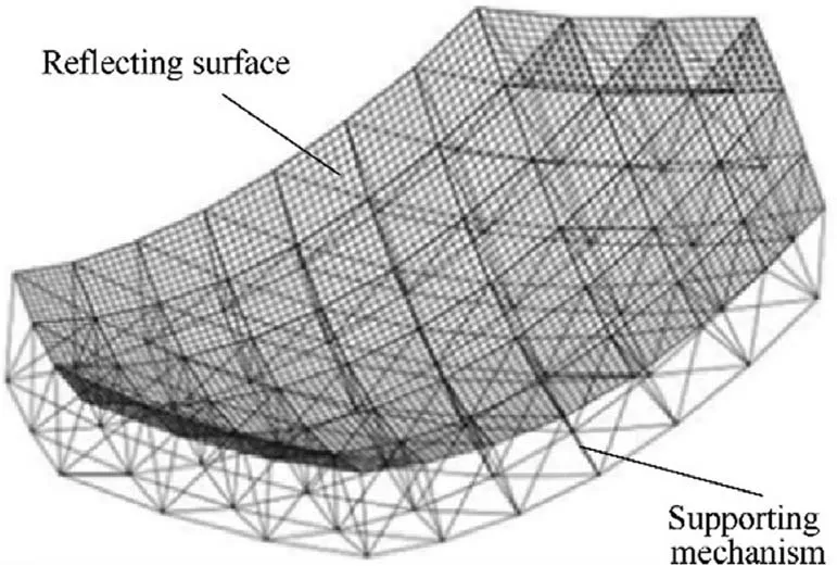
Fig.1 Schematic diagram of truss deployable antenna structure.
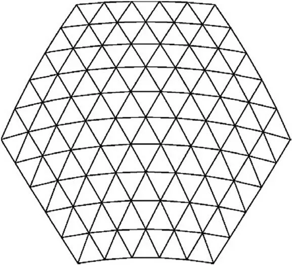
Fig. 2 Triangular division.
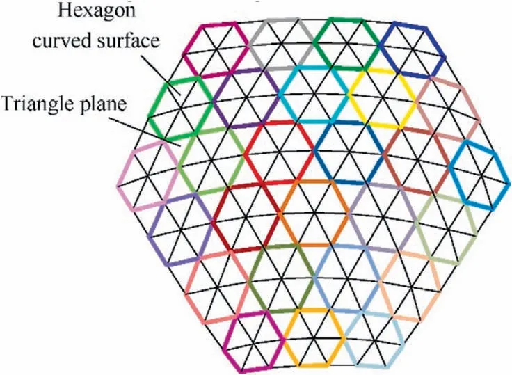
Fig. 3 Hexagonal division.
In this study, a new hexagonal profile division method is proposed,which uses curved hexagonal surfaces and triangular planes to approximate a paraboloid. As shown in Fig. 3, the entire paraboloid can be regarded as being composed of multiple hexagons and triangles. The three hexagons in the center(red,blue,and orange outline)are taken as an example to illustrate the distribution relationship. As it can be seen in Fig. 4,the three hexagons(①,②,③)are connected to form the middle triangle Ⅰ. Each hexagon is composed of six triangles and the center of each hexagon is not in the same plane of its six vertices, forming a hexagonal curved surface. Each hexagon meets certain geometric constraints: for the side lengths we have that loa=lob, loc=lod, and loe=lof, so the triangles oab, ocd, and oef are isosceles triangles. In addition, there is no special dimensional relationship between the side lengths laf, lbc, and lde. Different from the existing triangular division method, the proposed method is called hexagonal symmetric design due to the symmetry of the isosceles triangles.
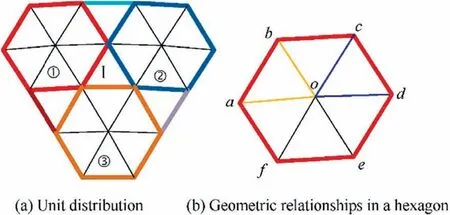
Fig. 4 Unit distribution and geometric relationships.
3. Deployable unit mechanisms and mobility analysis
3.1. Tetrahedral supporting mechanisms for triangular profile division
In the asymmetric design of antenna reflectors based on triangles, the deployable supporting mechanisms are mainly tetrahedral with triangular bottom. The most common mechanisms are 3RR-3RRR,9,243RR-3URU9, and 3UU-3URU21. According to Refs. 9 and 24, the 3RR-3RRR unit mechanism is a single-DOF mechanism. Fig. 5 shows a large deployable antenna constructed by 3RR-3RRR units. Since the reflecting surface of the antenna is generally spherical or parabolic, the orientation of each floral disc node on the reflecting surface must be different. Moreover, since this is a single-DOF mechanism, the orientation of all nodes is unchanged during folding. Therefore, antennas formed by 3RR-3RRR units have problems of not folding completely and low folding rate.Furthermore,while the 3RR-3URU unit mechanism is introduced in Ref.9,a detailed mobility analysis has not been performed yet.Consequently,a mobility analysis for this mechanism is conducted as follows.
As it can be observed in Fig.6,the mechanism of the 3RR-3URU deployable unit comprises four floral discs,three swing links, six synchronous links, nine revolute joints (R), and six Hooke hinges (U). Each U joint is equivalently represented by two revolute joints, whose two axes intersect vertically;for example, U11is represented as R11,1and R11,2. The upper ends of the three swing links are connected to the top disc by the revolute joints R7, R8, and R9, the lower ends are connected to the three bottom discs by the revolute joints R4, R5,and R6, and the centers of the three bottom discs are located on the same plane. The lengths of the links satisfy the following relationship: L1=L2=L3, L11=L12, L21=L22, and L31=L32. It should be noted that the axes of the three swing links intersect at point H,while the point O is the outer center of the triangle ABC.Then,the geometric relationships satisfied by the direction vector of each revolute joint (Fig. 6) are defined as: SR4//SR7⊥plane AOH, SR5//SR8⊥plane BOH, SR6//SR9⊥plane COH, SR11,1//SR1//SR12,1⊥plane U11R1U12, SR21,1//SR2//SR22,1⊥plane U21R2U22, and SR31,1//SR3//SR32,1⊥plane U31R3U32. The revolute axes of Ui1and Ui2(i=1,2,3) near the links point along the axial directions of the links,while the axes of the R7,R8,and R9are coplanar.Without loss of generality, SR1,SR2,SR3are not parallel to the plane ABC. The deployable tetrahedral 3RR-3URU unit belongs to the spatial multi-loop coupled mechanism, and its mobility will be analyzed using the link-demolishing and equivalent method.22The four floral discs of the unit are coupled components, and the chains connecting any two floral discs are coupled chains. Here, the URU chain between floral discs B and C is selected to be removed for analysis and the resulted mechanism is shown in Fig. 7. For convenience of analysis, a reference coordinate system OA-XYZ is defined platform connected to the base by two branches. Branch 1 is the U12R1U11chain,and branch 2 is R5R8-R7R4U32R3U31R6-R9, where R7R4U32R3U31R6R9is a single closed-loop chain.In the closed-loop chain, U32R3U31R6R9is a 7-DOF serial kinematic chain with no constraint on floral disc P. The kinematic twist systems of U12R1U11and R5R8R7R4in OA-XYZ are respectively expressed by Eqs. (1) and (2) as follows:on node A,with the origin OAcoinciding with the center of R4,the X-axis being parallel to the direction of the connection BA,the Z-axis being perpendicular to the plane ABC, and the Yaxis being determined by the right-hand rule.

Fig. 5 3RR-3RRR tetrahedral unit and its deployable mechanism.
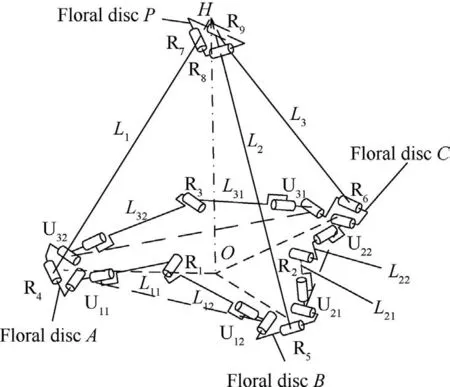
Fig. 6 3RR-3URU mechanism.
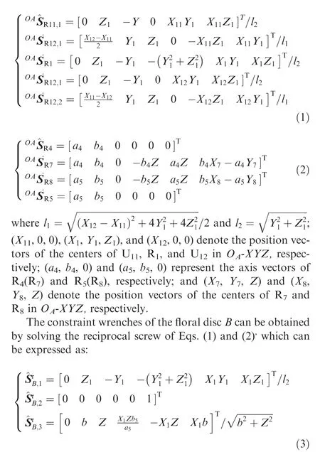
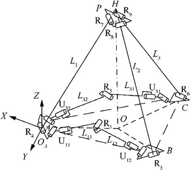
Fig. 7 Mechanism after removing the URU coupled chain.
In the next step, the motion relationship between the coupled components B and C, which are connected to both ends of the removed coupled chain,and the base A will be analyzed.According to the screw theory,20B is considered as the moving
where b=Y8-X8b5/a5.
Subsequently,the twists of floral disc B can be obtained by solving the reciprocal screw of Eq.(3),which can be expressed as:

According to Eq. (4), the floral disc B has two rotational DOFs,which are parallel to the X-and Y-axis,and one translational DOF along the X-axis.Similarly, the floral disc C has two rotational DOFs parallel to the X- and Y-axis, and one translational DOF along the CA direction. Therefore, the equivalent mechanism after the removal of the coupled chain is obtained, and, as shown in Fig. 8, the removed coupled chain can be restored. In Fig. 8, RXand RYrepresent the two rotational DOFs of B(C) relative to A about the X- and Y-axis, respectively, while PBAand PCArepresent the DOFs of B and C relative to A, respectively. The U21R2U22chain provides a constraint force along the R2axis, which limits the relative movement between B and C in this direction.Consequently,the translational DOFs of B and C relative to A are dependent,while,only RXand RYof the four rotational DOFs are independent, so the 3RR-3URU mechanism has three DOFs, that is, B and C not only have synchronous translational DOFs,but also have synchronous rotational DOFs with respect to A,providing the capability to adjust the orientation.
A symmetric mechanism composed of three basic 3RR-3URU units is illustrated in Fig. 9. The tetrahedra H-ABE,I-ADG, and J-ACF share the central floral disc A, and the two are connected by an URU chain.The mechanism satisfies the following symmetric geometric conditions: AB=AE,
AD=AG, and AF=AC. Moreover, the B, E, C, F, D, and G nodes on the reflecting surface lie on the same plane, which is not coplanar with node A. In order to increase the stiffness of the mechanism, three additional URU constraint chains were added between the top nodes H, I, and J.
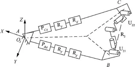
Fig. 8 Equivalent mechanism of 3RR-3URU unit.
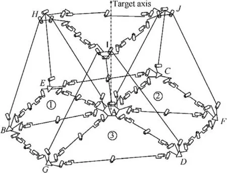
Fig. 9 Symmetric mechanism composed of three combined 3RR-3URU tetrahedra.
If only the connections between the bottom floral discs are taken into consideration, the combined mechanism can be equivalent to that shown in Fig. 10. If the three basic units are connected by the common floral disc A, and A is used as the base, then the three basic units can move independently,and the entire mechanism has nine DOFs. When the EC,FD, and GB chains are added, each URU chain provides a constraint force along the axis direction of the corresponding middle revolute joint, limiting the movement of each component at both ends along that direction. This means that the movements of E and C are related, the movements of F and D are related, and the movements of G and B are related. In addition, in the three basic units, the movements of B and E are related, the movements of C and F are related, and the movements of D and G are related.Therefore,each of the three added URU chains introduces a redundant constraint. After the three URU chains have been added between the top nodes H, I, and J, an inverted tetrahedron unit through the three swing links and the disc A is formed,whose geometric relationship is completely consistent with the other basic units. Thus,the movement of the inverted tetrahedron is associated with that of the other three basic units. The three URU chains at the upper layer only increase the rigidity of the mechanism,and do not affect its motion characteristics. Consequently, in the symmetric combined mechanism,there are four redundant constraints, no common constraint, and no local DOF.According to the modified Gru¨bler-Kutzbach(G-K) formula21–22, the DOFs of the mechanism can be calculated as:

where M is the number of DOFs, d is the order of the mechanism, d=6-λ, where λ is the number of common constraints, n is the number of all components including the base,g is the number of joints,fi(i=1,2,...,k)is the number of single DOFs possessed by the i-th joint, v is the number of redundant constraints besides the common ones, and ξ is the number of local DOFs.
The symmetric combined deployable mechanism based on 3RR-3URU units has seven DOFs. The floral discs on the reflecting surface not only have a DOF to move to the base A and achieve the folding movement, but also have a DOF to rotate relative to the base A and achieve the orientation adjustment, eventually accomplishing the complete folding of the mechanism. However, the orientation of floral discs can be adjusted only when the symmetric geometric conditions are satisfied.When forming large curved surface deployable mechanism, it cannot ensure that the combined units at different positions meet the symmetry, so it cannot form any large curved surface deployable antenna supporting mechanism.
Compared to the mechanism of the 3RR-3URU unit, the two ends of the swing links of the 3UU-3URU unit mechanism are connected to the floral discs through U joints (Fig. 11).According to the analysis in Ref. 21, in the 3UU-3URU unit mechanism, there are no common constraints and no local DOFs. According to the G-K formula, the DOFs of the 3UU-3URU unit mechanism are nine.A combined mechanism composed by three basic 3UU-3URU units is illustrated in Fig.12.As it can be observed,the three basic units share a central floral disc,and every two units are connected by an URU chain.The three top floral discs are also connected by a URU chain. According to the DOF analysis of the basic unit, the translational and rotational DOFs of each floral disc are not related,while,in the combined unit,each URU chain provides a constraint force, which limits the independence of the two translational DOFs of two adjacent floral discs. The DOFs of the combined unit are 3×9-6=21.
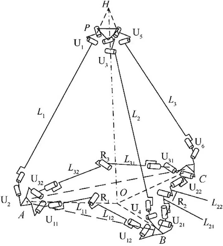
Fig. 11 Mechanism of 3UU-3URU unit.
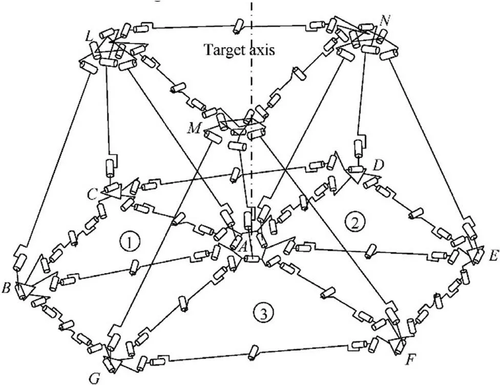
Fig. 12 Combined unit based on 3UU-3URU tetrahedra.
In the combined unit based on 3UU-3URU units, the motion of each floral disc is independent of each other, while it can be folded and its orientation can be adjusted. Consequently, the mechanism of a large deployable antenna can be composed of multiple combined units, and complete folding can be achieved.
3.2. Supporting mechanism design for hexagon profile division
The proposed supporting mechanisms for large tetrahedral deployable antennas will be composed of different tetrahedral units,similar to those analyzed in Section 3.1,through specific connection modes. It should be noticed that a single tetrahedral unit cannot represent the entire mechanism, thus, in this study, it will be called non-modular design. The modular mechanism proposed in the present study is composed of several modular units with the same characteristics and each of which can represent the characteristics of the entire mechanism; thus, it will be called modular design.
The design of the modular mechanism is based on a symmetric design method of antenna reflectors based on hexagon division. It is a modular mechanism composed of symmetric combined units that are based on 3RR-3URU tetrahedra.Fig. 13 shows a single-circle of the modular mechanism based on a symmetric combined unit of 3RR-3URU tetrahedra,which comprises three combined unit modules.Three U joints,namely,U1,U2,and U3,are used to connect the six peripheral nodes of the floral discs in the different modules, forming the closed-loop triangular mechanism Ⅰ.The first axis of U1,U11,is perpendicular to the triangular plane on which the triangular mechanism Ⅰlies, while the other axis, U12, is parallel to the direction defined by nodes B and C. The first axis of U2,U21, is perpendicular to the triangular plane, while the other axis, U22, is parallel to the direction defined by nodes D and E. Moreover, the first axis of U3, U31, is perpendicular to the triangular plane, while the other axis, U32, is parallel to the direction defined by nodes F and A. In order to enhance the stability of the mechanism, three boundary URU constraint chains are added, and the resulted reflecting surface forms a closed loop. If the constraint chain 1 is taken as an example,it can be seen that the constraint chain and the combined units①and ②form a closed triangle. The two connecting links of each constraint chain are equal in length.The axis of the intermediate revolute joint is parallel to the closed triangular plane,and perpendicular to the axes of the connecting links.The axes of the two revolute joints near the combined unit are parallel to that of the intermediate revolute joint, while the other two revolute joints point respectively along the axial directions of the two connecting links.
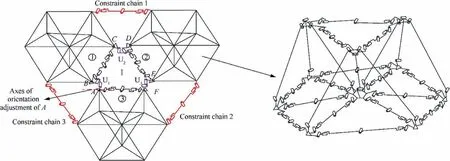
Fig. 13 Schematic diagram of modular mechanism based on 3RR-3URU tetrahedral symmetric combined unit.
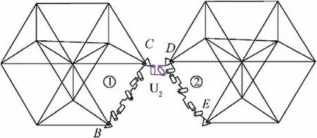
Fig. 14 Schematic diagram of connection between combined units ②and ①.
The DOF analysis of a single-circle of the modular mechanism is equivalent to that of the constraint function of the closed-loop triangular mechanism formed by three combined units and three additional boundary URU chains, namely, 1,2, and 3, which constrain the motion of the three combined units.The three combined units are connected,forming a modular mechanism.It should be noted that the mechanism can be also formed by adding the combined units ②and ③to the combined unit ①. As it can be observed in Fig. 14, when the combined unit ②is added to the combined unit ①,it is equivalent to connecting the two combined units in series with a U joint (U2). Each combined unit has seven DOFs, and each U joint has two DOFs. Therefore, the DOFs of the mechanism exhibited in Fig. 14 are 7×2 + 2 = 16. Moreover, as it can be seen Fig. 15, when the combined unit ③is added to the combined units ①and ②, the three combined units are connected, forming a closed loop. Meanwhile, the DOF analysis is equivalent to analyzing the constraint function of the triangular closed-loop mechanism presented in Fig. 16.
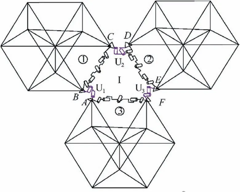
Fig. 15 Schematic diagram of addition of the combined unit ③to combined units ①and ②.
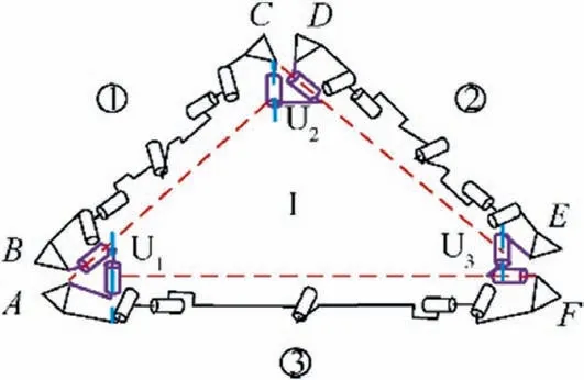
Fig. 16 Schematic diagram of intermediate triangular mechanism.
According to the analysis in Section 3.1, in addition to the orientation adjustment motion of each node,there is a relative translational motion between two nodes in order to achieve a synchronous folding motion in the combined unit. Therefore,the triangular mechanism shown in Fig. 16 can be equivalent to that shown in Fig. 17. In other words, the nodes A and F are equivalently connected by a translational joint P1, and the nodes D and E are equivalently connected by a translational joint P2. Therefore, this is equivalent to connecting an UPUPU constraint chain between two adjacent floral disc nodes on the reflecting surface of the combined unit. Moreover,a reference coordinate system o-xyz is defined at the center of U11. The y-axis coincides with U11, the x-axis, which is located on the triangular plane, is perpendicular to the yaxis,and the z-axis is determined based on the right-hand rule.
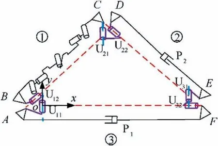
Fig. 17 Schematic diagram of equivalent mechanism of that shown in Fig. 16.
According to the screw theory,the twist system of the UPUPU chain is described as follows:
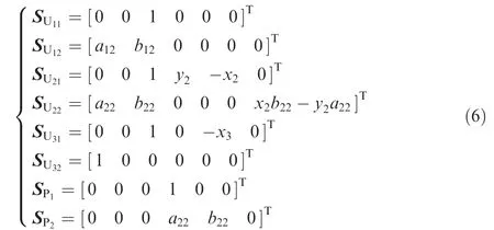
where (a12, b12,0) and (a22, b22, 0)represent the vectors of the U12and U22axes, respectively; (x2, y2, 0) and (x3, 0, 0) represent the position vectors of the centers of U2and U3,respectively.
The reciprocal screw of Eq. (6) can be calculated as:

According to Eq. (7), the UPUPU chain does not provide any constraint, the combined unit ①has still seven DOFs,and its motion characteristics remain unaffected.These results apply also to the combined units ②and ③. Therefore, the three added universal joints only connect the three combined units and do not affect the motion characteristics, which is the basic condition for modular design. If the node A is taken as an example and based on the DOF properties of the combined unit, the node A rotates around the axis of the revolute joint of its swing link and translates between the nodes A and F. Moreover, the axis of the revolute joint is perpendicular to that of the swing link and tangent to the circumscribed circle of the triangle at the bottom of the tetrahedral unit, where the disc A is located.
The addition of each of the three boundary URU constraint chains 1, 2, and 3 (Fig. 13) provides a constraint force parallel to the axis of middle revolute joints in the URU chain,which limits the translation of the nodes connected to both ends of the chain,and does not affect the adjustment of orientation. Consequently, the DOFs of the modular mechanism composed of three symmetric combined units based on 3RR-3URU tetrahedral units are 7×3-3 = 18. The proposed modular mechanism can perform synchronous translation and orientation adjustment of the floral disc nodes, and eventually achieve complete folding.
4.1. Profile division based on triangular asymmetric design
The improved three-dimensional mesh method37is applied to perform the triangular profile division of the paraboloid. The main steps are as follows:
(1) The initial profile error δrmsand the side length l of the triangular unit need to satisfy:

As demonstrated in Fig. 18, on the aperture surface, the inner regular hexagon of the aperture circle is divided into regular triangular units of same size.
(2) A new paraboloid mapping can be obtained by translating the ideal paraboloid along its external normal direction, the translation distance d =l2/16f.
(3) The mesh nodes on the aperture surface are mapped to the mapping paraboloid in order to obtain the positions of all nodes, and the division of the ideal paraboloid is completed.
The paraboloid aperture is set toD=6 m,the focal diameter ratio tof/D=0.45,and the initial profile error to δrms=2-mm. The side length l ≤578.4685 mm of equilateral triangles on the aperture surface can be determined by Eq. (8). After rounding,the value is set to 500 mm,and thus,the fine fraction on the aperture surface is N=12. Finally, the triangular
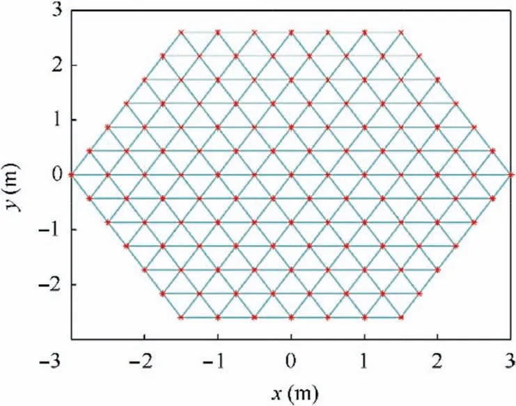
Fig. 18 Triangular division on aperture surface.
4. Reflector profile division based on different division methods
A truss deployable antenna can be divided into the positivefeed antenna and the biased-feed antenna. The metallic mesh of the reflecting surface of the truss antenna is fixed on the deployable supporting mechanism to reflect electromagnetic wave signals.The reflecting surface can be regarded as a number of small connected planes; thus, the reflecting accuracy of the metallic network is determined by the profile accuracy of the supporting mechanism.For the sake of simplicity,the profile division and fitting error of the positive-feed paraboloid reflector will be investigated based on an asymmetric and a symmetric design method.profile division is completed in MATLAB R2018a, and the result is presented in Fig. 19.

Fig. 19 Triangular profile division of a paraboloid with an aperture of 6 m.
4.2. Profile division based on hexagonal symmetric design
Again, the improved three-dimensional mesh method is applied to perform the hexagonal profile division of the paraboloid. The main steps are as follows:
(1) Firstly, the side length lBof the triangle is determined based on the given initial profile error δrmsand Eq.(8). Then, a regular hexagon is drawn with a center defined by the common node of its triangles, and each regular hexagon had side length defined by lA=√---3/2lB. It should be noted that the aperture surface can be divided into regular triangles and regular hexagons of same side length, with the nodes of the hexagons being the nodes of the triangles (Fig. 20).
(2) The hexagon nodes on the aperture surface are mapped to the paraboloid along the direction of its rotation axis(Fig. 21).
(3) The location of the central nodes of the hexagons on the paraboloid is determined according to symmetry. It should be mentioned that the distance between the central nodes and the paraboloid should be minimized in order to ensure that the error of the division result is minimum. Fig. 22 shows the completed division of the ideal paraboloid.
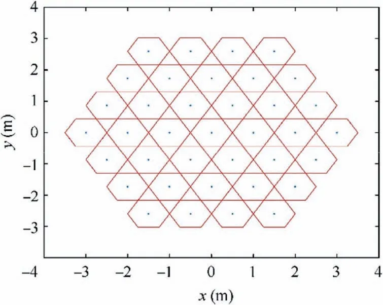
Fig. 20 Hexagonal division on aperture surface.
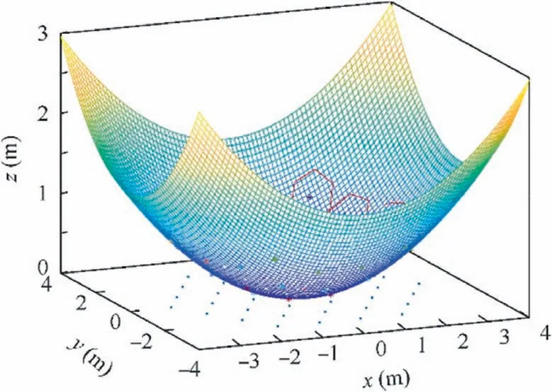
Fig. 21 Nodes mapping from aperture surface to paraboloid.
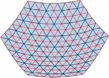
Fig. 22 Hexagonal profile division of a paraboloid with an aperture of 6 m.
Again,the paraboloid parameters of triangular division are used to complete the hexagonal profile division in MATLAB R2018a.
4.3. Results and analysis of the two profile division methods
In order to facilitate post-processing and assembly, the types of links after division should be as few as possible, while the link length should be as close to the set length as possible.Consequently,based on the evaluation index of link unity,a quantitative analysis of the two division results is performed. The evaluation indexes mainly include the average length of linksL-,the standard deviation of link length δL, and the coefficient of uniformity of link length UL.
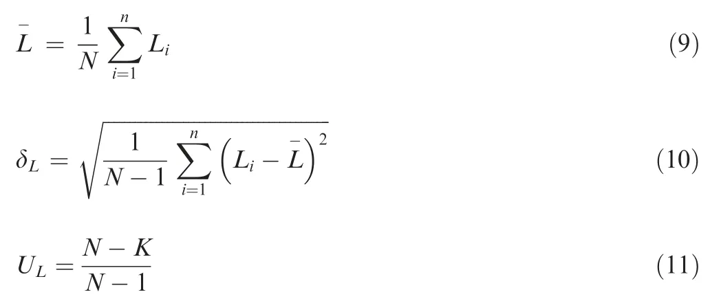
where N is the number of links,Liis the length of the i-th link,and K is the number of link types. The closer the L-to the set length, the more ideal the link length. The smaller the δL, the more even the link length.Since ULis defined between 0 and 1,the closer the ULto 1,the better the uniformity of link length.
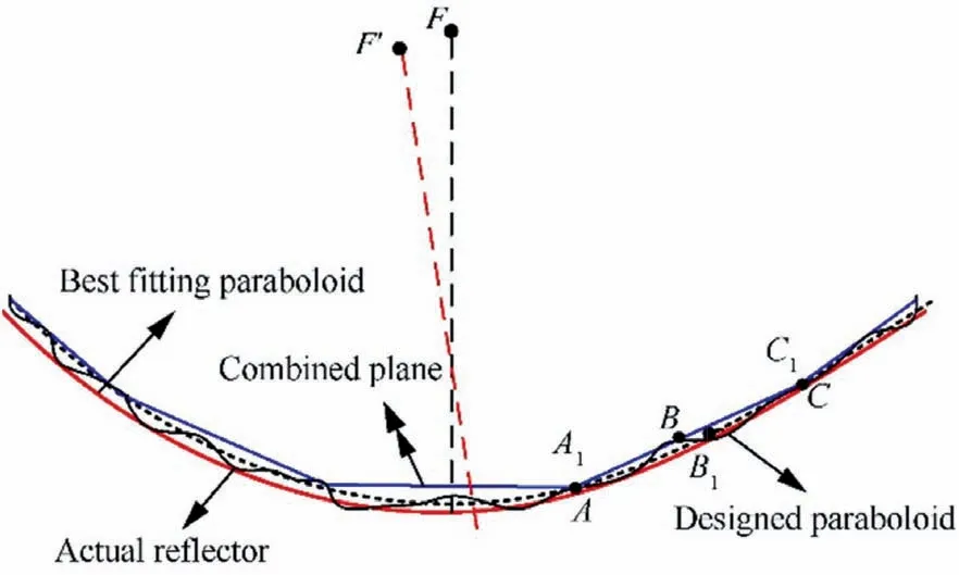
Fig. 23 Best fitting paraboloid.
As a matter of fact, a new paraboloid can be found that coincides with the actual reflecting surface. While there are countless paraboloids,only one can best coincide with the minimum root mean squared error(RMSE)of the actual reflecting surface.The independent parameters that describe the paraboloid are the position of the paraboloid vertex and the value and direction of the focal length. Therefore, the displacement uA,vA, and wAof the best fitting paraboloid vertex, the focal axis direction φxand φy, and the change amount h of the focal length need to be determined. After profile division, all the nodes of the combined plane are on the designed paraboloid,thus, at this point, the best fit paraboloid coincides with the design paraboloid. However, the actual reflector incorporates the later fixed metal mesh, where the fixed node of the metal mesh includes the synchronous hinges between two synchronous links in addition to the three vertices at the bottom of the basic unit(Fig. 23). Consequently, the best fitting paraboloid needs to be calculated based on the displacement of each node on the actual reflecting surface.
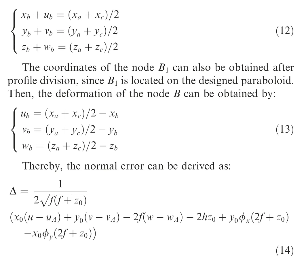
At this point,the deformation of the nodes A,B,and C can be calculated using the least square method as follows:
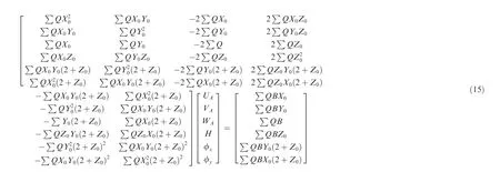
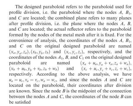

The parameters of the best fitting paraboloid can be calculated according to Eq. (15), and then, the parameters can be imported into Eq. (14) to obtain the normal error.
When a large paraboloid is divided into several geometric units, the factors affecting the fitting accuracy include the paraboloid parameters, the division method, and the fitting method.The evaluation indexes of the results of the two methods obtained under the same conditions are listed in Table 1.It can be seen that the link length of the triangular division is closer to the initial length,and the RMSE is smaller.On the other hand,the uniformity of link length of the hexagonal division is better, but the RMSE is a little larger.
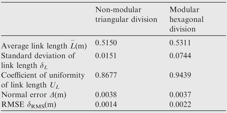
Table 1 Evaluation indexes of two profile division methods.
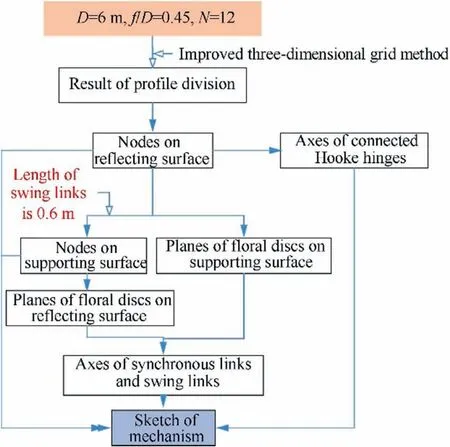
Fig. 24 Flow chart of drawing process of large modular deployable antenna mechanism line model.
5. Modeling of the modular deployable antenna mechanism and comparative analysis of performance indexes
5.1. Modeling and simulation of the modular mechanism
Based on the profile division results,the constraint relationship of each unit and the topological relationship between units,the coordinates of each node, and the position and direction of each axis are calculated in MATLAB. Afterwards, the produced data files are exported, and a 3D line model is formed by importing the data files into SolidWorks. A paraboloid reflector with an aperture of D=6 m, focal diameter ratio of f/D=0.45, and fine fraction of the aperture surface of N=12 is taken as an example. The improved threedimensional mesh method is applied to divide the surface of the reflector, and SolidWorks 2018 is used to develop a line model according to the process presented in Fig. 24. A 3D sketch of the entire supporting mechanism including all the parameters, such as node position, motion pair position and orientation, and link length is obtained (Fig. 25).
In order to visually describe the motion of the mechanism,a single-circle modular mechanism is selected for 3D modeling(Fig.26(a)).The mechanism model is simplified and imported into the Adams dynamic simulation software for the simulation. Constraints, actuators, and others are added. The number of DOFs in the mechanism is the minimum number of actuators required to determine the motion of the mechanism.According to the DOF analysis in Section 3.2,the single-circle modular mechanism has 18 DOFs,and therefore,18 actuators should be reasonably added to the simulation model.The position of the imported actuators is presented in Fig. 26 (b). The positions 1–12 of the revolute joints connecting the reflecting surface discs(the nodes on the reflecting surface)and the swing links are chosen to place the folding actuators, and the positions 13–18 of the revolute joints connecting the back discs(the nodes on the back surface)and the swing links are chosen to place the orientation adjustment actuators. This way the modular antenna mechanism could achieve folding and orientation adjustment until it reaches fully folded state (Fig. 26(c)).
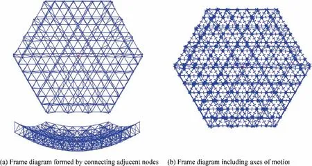
Fig. 25 Supporting mechanism model for a paraboloid antenna with a diameter of 6 m.
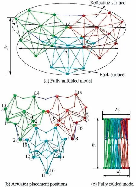
Fig. 26 Single-circle modular mechanism.
5.2. Comparative analysis of the modular and non-modular mechanisms
Based on the different motions that the mechanisms can perform, the modular and non-modular deployable antenna mechanisms investigated in this paper can be divided into three states:fully unfolded state,only folding state,and fully folded state.In order to characterize the folding capacity of the different mechanisms,the ratio of the space volume occupied by the mechanisms in the fully unfolded state to the final state (including the only folding state and fully folded state) was defined as the folding rate of the mechanism. The folding rate can be expressed by:

where V0and Vfdenote the volume of the deployable antenna mechanism in the fully unfolded and folded state,respectively;D0,d0,and h0denote the diameter of the envelope circle of all nodes on the reflecting surface, the diameter of the envelope circle of all nodes on the back, and the maximum distance between the reflecting surface and the back, respectively.
Based on the two design methods investigated in this paper,a series of supporting mechanisms for truss deployable antennas can be designed. For comparative analysis, three nonmodular mechanisms are selected based on the triangularasymmetric design and one modular mechanism is selected based on the hexagonal symmetric design.The analysis results are presented in Table 2.
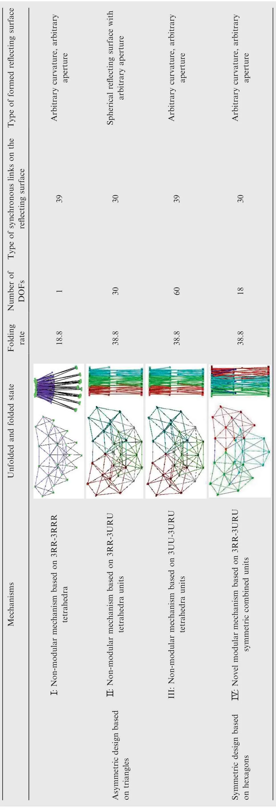
Table 2 Comparative analysis of truss deployable antenna mechanisms derived based on two design methods.
In Table 2, the initial and final state models of the four mechanisms are presented. It should be mentioned that the space volumes occupied by the mechanisms in the fully unfolded state are equal, and all apertures are 2.174 m. The folding rate of the four mechanisms can be calculated according to Eq. (16), and the number of DOFs can be obtained according to the analysis in Section 3. In this paper, the links on the reflecting surface are considered.Without loss of generality,in mechanisms I and III,the distances between nodes on the reflecting surface are not consistent according to the triangular division principle of paraboloid. Therefore, the type of synchronous links of the two mechanisms is the number of connecting lines between the nodes on the reflecting surface.In mechanisms II and IV, each hexagonal combined unit is symmetric, thus, the type of links is relatively reduced.
Table 2 indicates that the design of various large deployable antenna mechanisms can be achieved based on the two design methods. Modular mechanisms based on the hexagonal symmetric design, can form reflectors with arbitrary curvature and aperture, with two types of DOFs concerning folding and orientation adjustment. The proposed design can achieve complete folding, with a large folding rate about twice that of mechanism I. Compared to mechanism III, the number of DOFs and type of links of the modular mechanism are reduced, which increases the reliability of the structure and reduces the cycle time and cost of the manufacture.
6. Conclusions
(1) Aiming at the truss deployable antenna mechanisms with paraboloid reflectors,this paper introduces an original asymmetric design method based on triangles,and a novel symmetric design method based on hexagons is proposed.Three types of mechanisms based on triangular asymmetric design are introduced and a novel modular deployable antenna mechanism based on hexagonal symmetric design is proposed. The characteristics and the mobility of the four mechanisms are acquired.
(2) A positive-feed paraboloid antenna with 6 m aperture is taken as an example to perform triangular and hexagonal profile divisions. The analysis results demonstrate that the proposed hexagonal division method has certain advantages and disadvantages compared to the original triangular division method, and both have a certain application prospect.
(3) A simulation model of the modular deployable antenna mechanism is developed based on the hexagonal division results in order to verify the DOFs and the deployment performance. Furthermore, a comprehensive comparative analysis is conducted on the characteristics of mechanisms suitable for triangular and hexagonal profile divisions. The results demonstrate that the modular mechanism has significant advantages compared to the three mechanisms based on the triangular asymmetric design.
To summarize, compared to the original triangular asymmetric design method,the hexagonal symmetric design method has certain advantages in the unity of the link length,although the profile accuracy is slightly lower. The modular mechanism suitable for such profile division has obvious advantages in the aspects of folding rate,number of DOFs,processing,manufacturing, and assembling. Therefore, the profile division method based on symmetric hexagons and the modular deployable antenna mechanism have preferable application prospects.They are more suitable for the design of truss deployable antenna mechanisms within the scope of meeting the accuracy requirements. Furthermore, further research on the application of modular deployable antenna mechanisms will be conducted, and effective methods to improve the accuracy of the antenna profile will be explored.
Acknowledgements
This study was co-supported by the National Natural Science Foundation of China(No.51675458),the Key Project of Natural Science Foundation of Hebei Province of China (No.E2017203335), and the Postgraduate Innovation Subsidy Project of Hebei Province of China (No. CXZZBS2019050).
 CHINESE JOURNAL OF AERONAUTICS2021年8期
- CHINESE JOURNAL OF AERONAUTICS的其它文章
- A novel virtual material layer model for predicting natural frequencies of composite bolted joints
- Multi-layered plate finite element models with node-dependent kinematics for smart structures with piezoelectric components
- Modeling bending behavior of shape memory alloy wire-reinforced composites: Semi-analytical model and finite element analysis
- Sequential ensemble optimization based on general surrogate model prediction variance and its application on engine acceleration schedule design
- Transition prediction and sensitivity analysis for a natural laminar flow wing glove flight experiment
- Modeling on mechanical behavior and damage evolution of single-lap bolted composite interference-fit joints under thermal effects
