Application of stress wave theory for pyroshock isolation at spacecraft-rocket interface
Xixiong WANG, To YU, Huipeng YAN, Jifeng DING, Zhen LI,Zhoye QIN, Fulei CHU
a School of Electromechanical and Automotive Engineering, Yantai University, Yantai 264005, China
b Department of Mechanical Engineering, Tsinghua University, Beijing 100084, China
c Xi’an Research Inst. of High-Tech, Xi’an 710025, China
d Beijing Institute of Spacecraft System Engineering, Beijing 100094, China
KEYWORDS Finite element method;Pyroshock isolation;Spacecraft-rocket interface;Stepped rod;Stress wave transmission
Abstract A large number of pyroshock devices are employed in spacecraft and rockets to realize stage separation and appendage deployment.Release of pyroshock devices induces high-level transient shock responses which tend to cause fatal damages in electronic equipment made of crystals and brittle materials. This paper aims to provide methods to isolate pyroshock and guarantee the safety of such equipment against high-frequency shocks. Firstly, stress wave transmission mechanism in stepped rods is investigated, upon which optimal area rate for shock isolation is achieved.Then,two spacecraft-rocket interface structures for pyroshock isolation,namely isolation hole and interim segment,are proposed.Both numerical simulations and experiments are carried out to validate the two shock isolation strategies.It is revealed that the interim segment structure shows better pyroshock isolation performance at the cost of increasing the weight of launching system whereas isolation hole is an optimal choice to reduce pyroshock response without causing weight increase.
1. Introduction
In aerospace engineering, pyrotechnic devices such as separation nuts,explosion bolts and Marman clamps are widely used for the connection and separation of spacecraft-rocket systems.1–4During the release of those pyrotechnic devices,harsh mechanical environment known as pyroshock is inevitably induced by explosions with high frequency, short duration and high g acceleration shock response, which could damage the nearby micro mechanism and hardware sensitive to high–frequency shock, and even cause disastrous flight accidents.
Moening showed that 74%of the 85 flight failures occurred from 1963 to 1985 were provably or highly suspected caused by pyroshock.5In order to guarantee the reliability of launching missions, several studies have been performed and many standards,test methods and software on pyroshock have been developed since 1960 by National Aeronautic and Space Administration (NASA),6European Space Agency (ESA),7Sandia National Laboratories(SNL)8,9and United States Military (USM).10
The published literature on pyroshock has mainly focused on the modeling and experiments of different pyrotechnic devices11–14and there are relatively few reports on pyroshock isolation.Although researchers have developed different types of shock isolators using linear and nonlinear stiffness/damping to reduce mechanical shock response,15–19they are inapplicable to pyroshock isolation at spacecraft-rocket interface since adding springs, dampers or semi-active actuators at spacecraft-rocket interface is highly restricted in aerospace engineering. NASA proposes that damping elements such as rubber/silicone pads can be used as shock absorber for shock isolation in early 1970s.6But the special physical environments in aerospace with high temperature and strong ultraviolet light lead rapid aging problem for traditional damping elements constitute of rubber or silicone. This problem is alleviated by the development of new damping material such as metal rubber and shaped memory alloy, which is proposed and well adopted in the vibration and shock control field.20,21However,the introduction of these shock absorbers will inevitably decrease the connection stiffness between spacecraft and rocket.This effect of stiffness will change the modal and aerodynamic performance of the spacecraft. Consequently, the application of damping elements for pyroshock isolation is highly limited in practical engineering.
Instead, changing geometric configuration along shock wave transmission path is a more practical and common method used in pyroshock isolation. Early comprehensive studies on structural connections and distance were conducted by NASA6and it was found that the wave impedance of interface was changed with the variation of geometrical structure and material leading to the variation of wave transmission and reflection to isolate shock response. An impact gasket composed of sheet metal was designed by Roggero in 2000 for a scientific experimental satellite named SAC-B.22The obtained results showed that shock response on the satellite was decreased by a small reduction in the stiffness level of connection. The whole spacecraft passive isolation system known as SoftRide and ShockRing was designed as a complicated transfer path for high frequency shock isolation based on a series of highly damped flexures and structures.23Flight experiments proved prominent attenuation of shock response of this system. Recently, Lee et al.24conducted numerical and experimental studies to examine the pyroshock attenuation effects of joints and washers.
In fact, according to stress wave theory, some typical variations of geometry can be utilized to isolate pyroshock.Recent evidences suggest that stepped rod, which is commonly used and easily fabricated in mechanical industry, is capable of affect stress wave transmission. Recent work by Gan et al.revealed that stepped rod could block stress wave and filter shock response with certain frequency band.25,26In this paper,firstly a pyroshock isolation method based on stepped rod is introduced. Then, the optimal area rate of isolation structure is discussed. Furthermore, two spacecraft-rocket interface structures, isolation hole and interim segment, are designed for pyroshock isolation based on the proposed mechanism.Both numerical and experimental studies are conducted to evaluate the pyroshock isolation effects of the two design strategies. Finally, suggestions on choosing pyroshock isolation methods are given.
2. Pyroshock isolation at spacecraft-rocket interface
2.1. Description of pyroshock problem
Fig. 1 shows a certain type of spacecraft-rocket interface of point-to-point connections, whose geometric dimensions are summarized in Table 1. The gram-centimeter-microsecondmega bar(g-cm-μs-Mbar)unit system is adopted in this model for decrease calculation error, where 1 g=10-3kg,1 cm=10-2m, 1 μs=10-6s, 1 Mbar=1011Pa. The pyroshock source, namely the separation nut, is mounted using bolt hole at interface.The separation nut is actuated by explosive to realize separation action as shown in Fig. 2. A Cartesian coordinate system (x, y, z) fixed at the geometric center of explosive is defined to describe the pyroshock response of the interface. For detailed description and parameter values of the separation nut, one can refer to our previous work.12
2.2. Theoretical analysis of stepped rod
Pyroshock is generated at rocket side and travels through the interface to spacecraft side. Hence, shock response along primary direction z, as shown in Fig. 1, is much stronger than those along the other two directions. Consequently, the pyroshock problem can be qualitatively evaluated using a one dimensional (1D) rod model.
Elementary rod theory is a classical theory and is well described in most textbooks and standards related to vibration and wave.4 In this theory, longitudinal displacement is assumed to be constant at all points along cross section and is expressed as u=u(x,t). The motion equation of free longitudinal vibrations can be obtained as
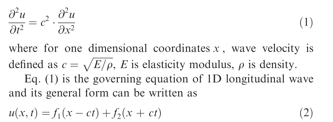
For a right-traveling condition, the speed and strain of a stepped rod in Fig. 3(a) can be obtained.

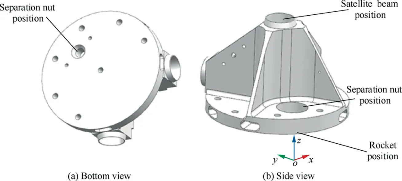
Fig. 1 Original spacecraft-rocket interface.

Table 1 Geometric dimensions.
where ε(x, t) is longitudinal strain, v(x, t) is longitudinal velocity.
The conservation equation of equilibrium and material speed in the discontinuity interface can be obtained as:
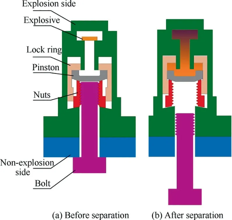
Fig. 2 Separation mechanism.

where σI, σRand σTare the stresses of incident, reflected and transmitted waves, and vI, vRand vTare this corresponding speeds respectively.By combining Eqs.(5)and(6),stress transmission rate σT/σIand stress reflectivity rate σR/σIcan be written as
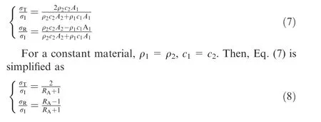
where RA=A2/A1is area rate.
Beside single stepped rod,the necked rod shown in Fig.3(b)is also commonly used,whose stress transmission and reflectivity rates can be expressed as


Fig. 3 Schematic of stepped rod.
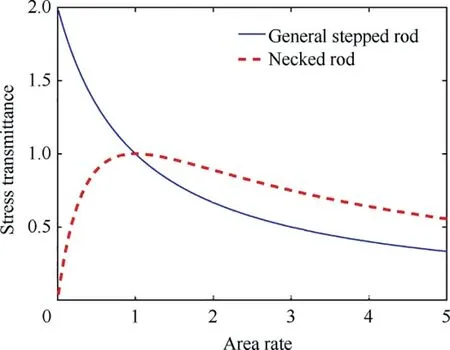
Fig. 4 Stress transmission rate by area rate.
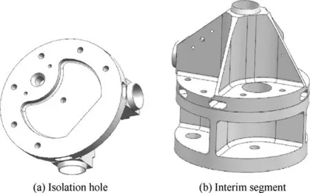
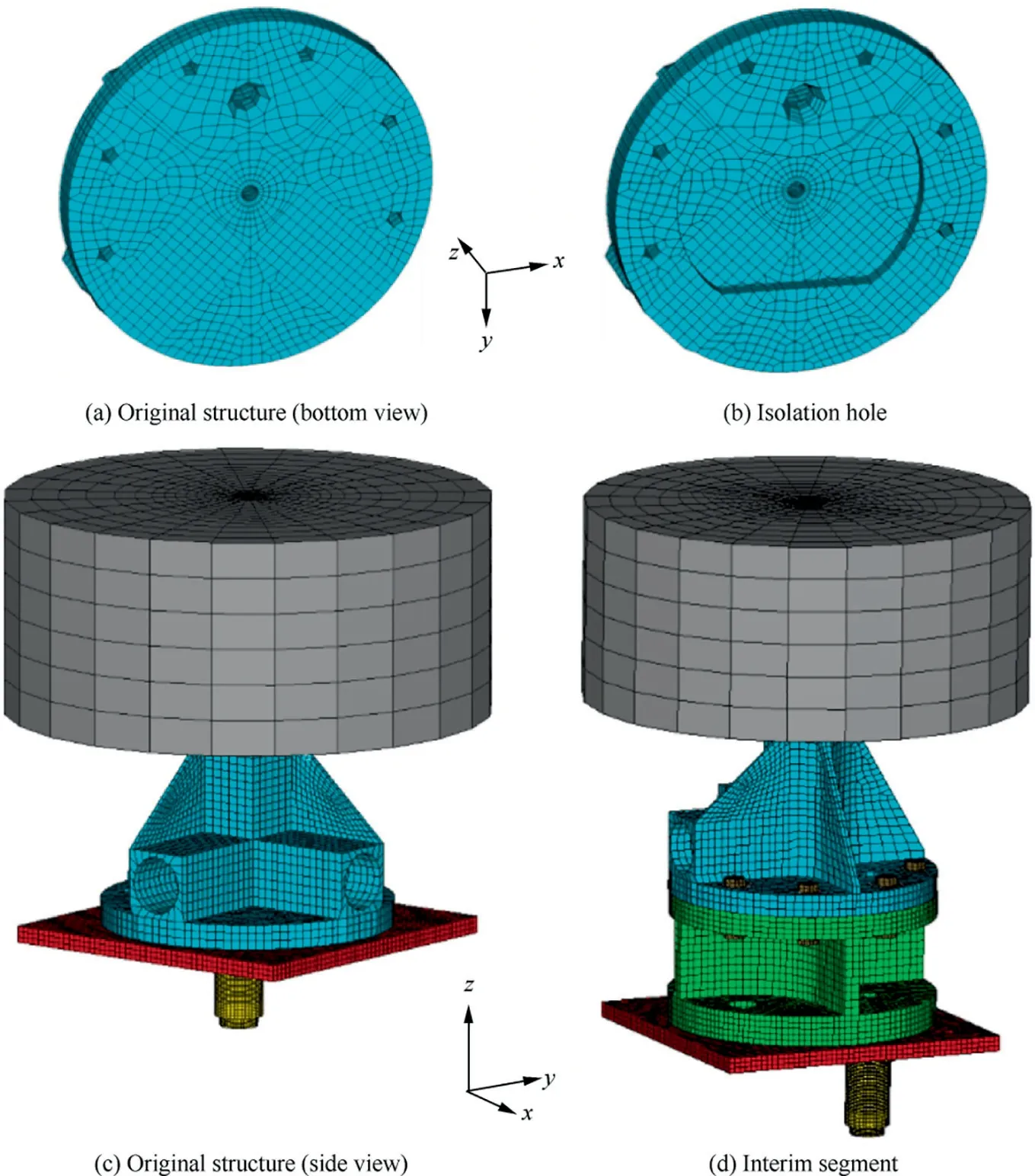
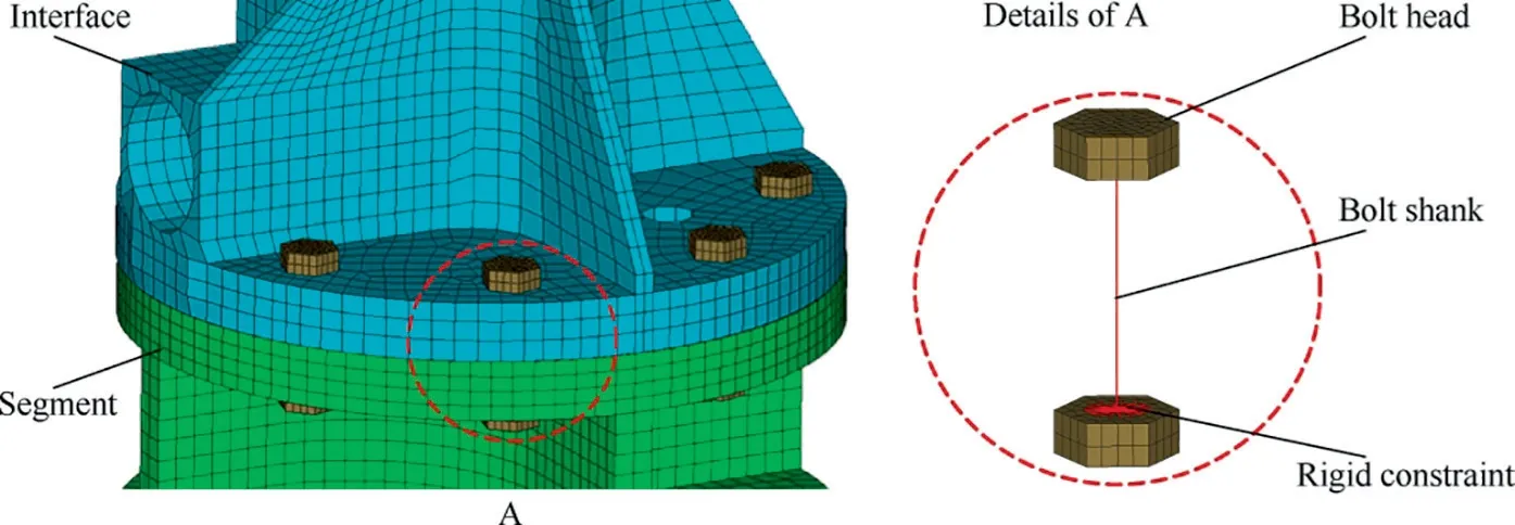
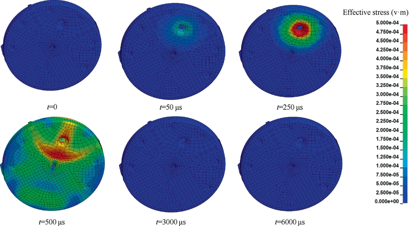
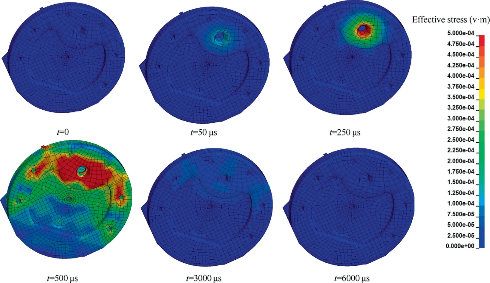
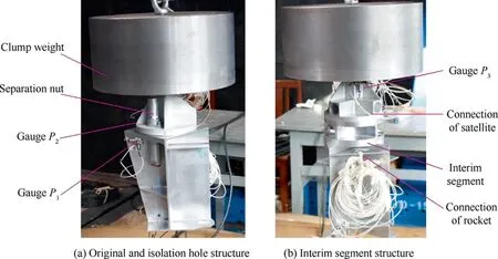
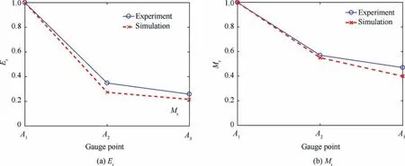
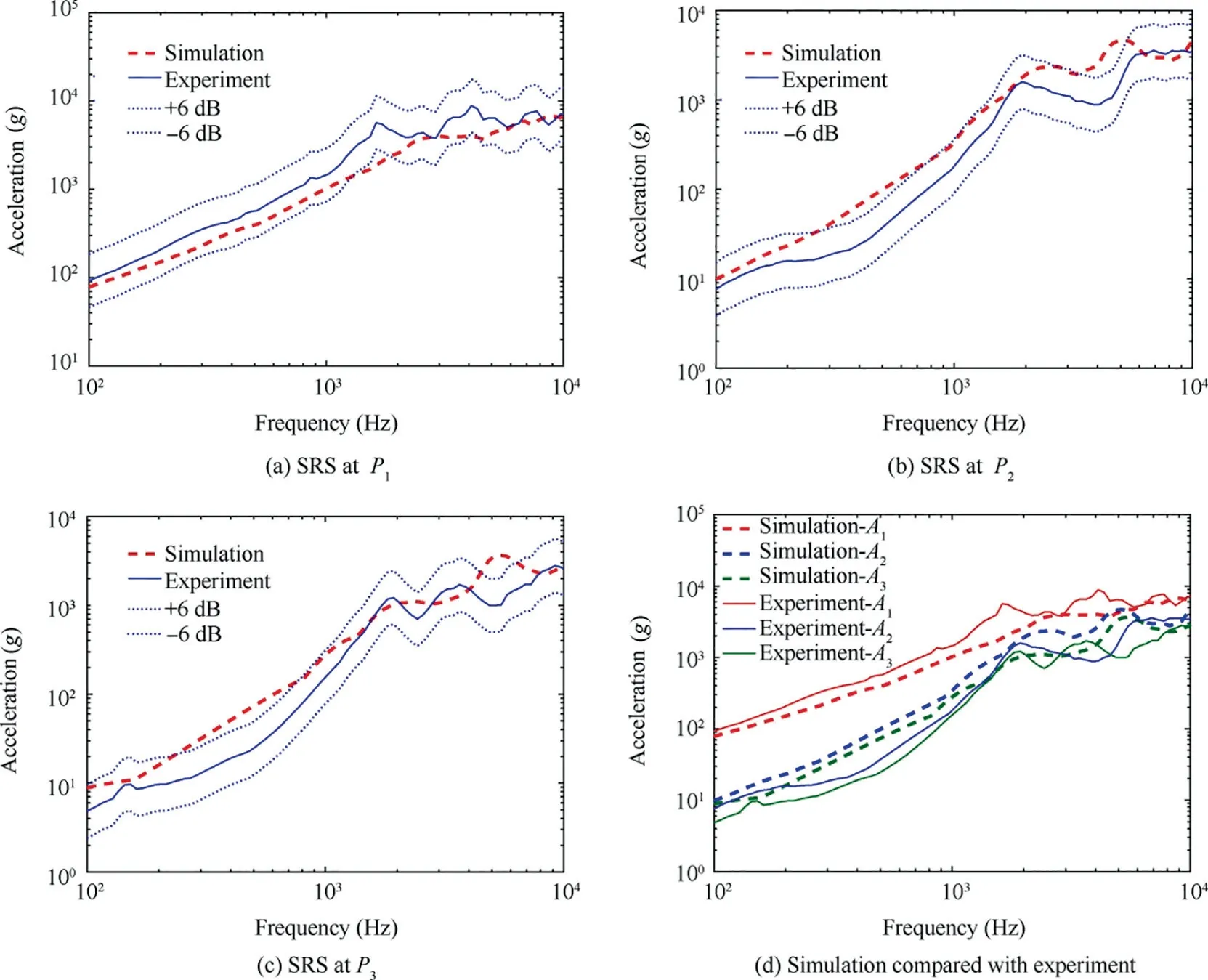
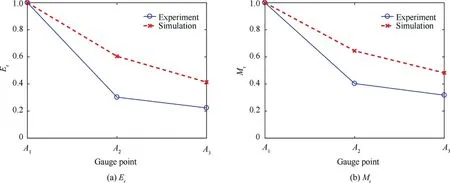
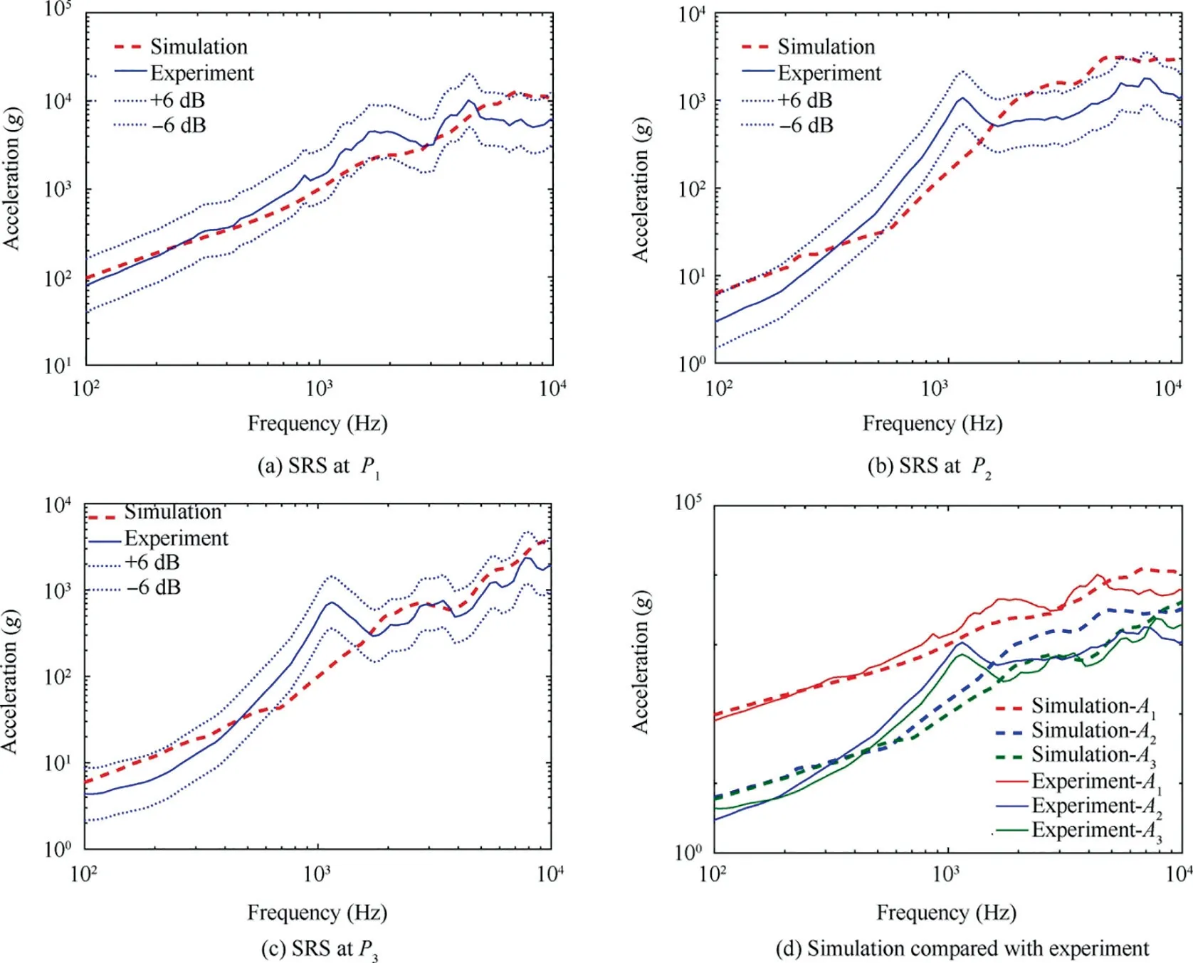
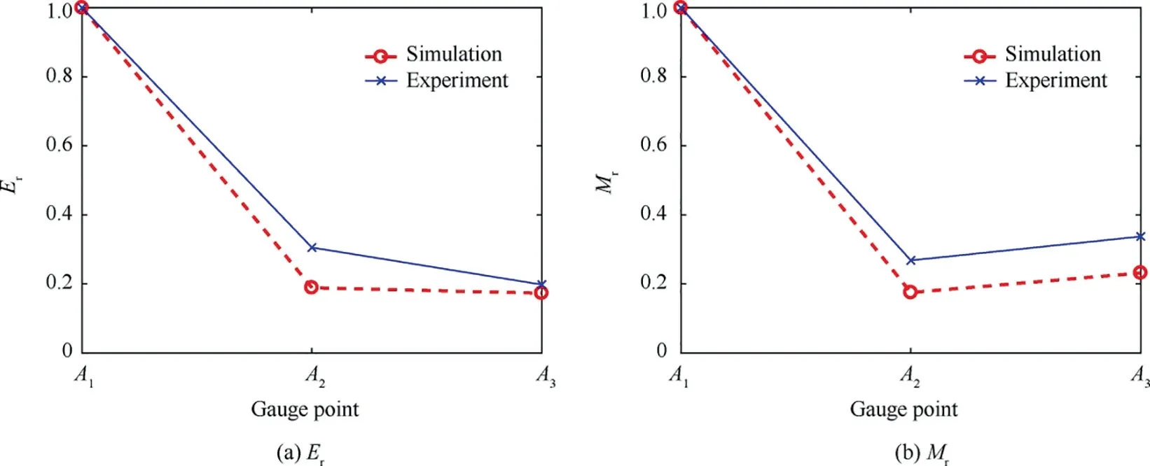
Since stress transmission rate has great effect on shock response, the parameter analysis of area rate is carried out as shown in Fig. 4. For single stepped rod, transmission rate is in the form of a hyperbolic decreasing function of area rate.For RA=1, stepped rod degrades to a uniformed rod with σT=σI, meaning that all waves travel through the rod without any loss. Under the conditions of RA<1 and σT>σI,stress is amplified which is disadvantageous for shock isolation. For A2=∞, we have RA= ∞, σT/σI=0 and σR/σI=1, and wave is fully reflected without any transmission.In order to realize shock isolation, that is, σT<σI, the condition of RA>1 should be ensured.However,the attenuation of stress transmission rate decreases by increasing area rate. By increasing area rate from 1 to 2, transmission rate is significantly decreased by 33.3%, while it is decreased by 16.7%for further increase of area rate from 2 to 3. This valve is reduced to only 10% when area rate is increased from 3 to 4.High area rates tend to decrease connection stiffness, which could lead to vibration problems at low-frequency region.Area rate threshold of 1/4 For necked rods, stress transmission rate is first increased and then decreased. The extreme and maximal value σT=σIis achieved at RA=1, which is the point of intersection of the curve of single stepped rod as well.The stress transmission rates of necked rods are always lower than those of rods with uniform cross sections. Therefore, geometric designs with necked rods are always beneficial for stress wave attenuating and shock isolation. Because of its simplicity and effectiveness,stepped rod method can be applied to improve pyroshock environment.In this section, an application of stepped rod method to isolate pyroshock is presented. Fig. 5 Modified model of spacecraft-rocket interface. From the results presented in Section 2.2, it can be concluded that area rate and type of stepped rod are critical parameters affecting stress wave transmissivity. However,there is difference between theoretical analysis and actual situations in aerospace engineering, where some constraints have to be taken into account.In this application,necked rod is preferred over single stepped one considering the geometry of spacecraft-rocked interface studied here. In the neck model shown in Fig. 3 and Eq. (9), when RA>1, higher area rates decrease stress transmission rate.Nevertheless,due to the constraint condition of structural strength as well as modal and aerodynamic configurations, it is unpractical to obtain high area rate without any limitation. For the isolation hole structure shown in Fig. 5(a), where a blind hole is designed at the bottom of the interface, the maximum area rate A2/A1of this structure is 0.5 and its stress transmission rate is 89%. To obtain higher area rates for more significant shock isolation,another structure called interim segment is designed as shown in Fig.5(b).This structure has one segment similar to the original structure with no isolation hole.To change the area rate of the interface, another segment with two disks connecting by cross shaped ribs on the rocket side is introduced. At the cost of weight increase, the interim segment structure can decrease the transmission rate to 72% for A2/A1=0.3125. In this section, finite element (FE) models for original and modified structures are developed to investigate the pyroshock isolation effects of the two designs proposed in Section 2.3. FE models are developed as shown in Fig.6,where high quality hexahedral elements are adopted in all components for the calculation of transient shock problems.In this paper,Jonson-Cook (JC)material model is utilized, which is well established and commonly used for impact dynamics. The spacecraftrocket interface and interim segment are all fabricated by 30CrMnSiNi2A. The properties of 30CrMnSiNi2A including equation of state (E.O.S.) properties of hydrostatic pressure and JC strength are summarized Table 2. There are 44853 nodes and 34,898 elements in the original structure. The number of isolation hole is 45852 nodes and 35706 elements. Since extra segment introduced, the interim segment has the largest calculating amount with 64595 nodes and 49708 elements.The load acting on the FE models is only the contact force induced by separation nuts,which is obtained in the near field Hydrocodes computation from our former study,12and applied as node forces by Saint-Venant’s principle in the separation nuts. To simulate the real environment of outer space, free boundary conditions are applied to the FE models. Fig. 6 FE model of three types of spacecraft-rocket interface. Table 2 Material properties of 30CrMnSiNi2A.27 In the interim segment structure,surface-to-surface contact is defined between the bolt heads and the joint parts, that is,the segment and interface.The contact status between the joint components and the interface,which has great influence on the shock transmission, is simulated based on the penalty method widely used in explicit codes. The preload is considered by defining 6 M8 bolts between the segment and the interface.Since the bolt is simply used for the connection between the spacecraft and the rocket without looseness and failure, the precise modeling of thread is unnecessary. The bolt head is constructed using 3D structural solid elements as shown in Fig.7,where beam elements with rigid constrained connection are used to model the shank.This simplification is appropriate with striking a balance between computational accuracy and efficiency. Fig. 7 Bolt modeling in interim segment FE model. Fig. 8 Von-mises stress in interim segment structure with bolt preload. Dynamic relaxation method is employed to apply preload onto the bolts with the preload level given by where, K=0.2 is torque coefficient, T is torque, and d is bolt diameter. Referring to application data, T=20 N∙m,d=0.008 m are adopted. Correspondingly, preload level F0of 12.5 N is used in the following simulations. In the process of preloading via the dynamic relaxation method, an initial axial force is applied to the beam elements of bolts to generate the preload force. The undesired high dynamic response caused by preloading is removed by defining Rayleigh mass damping α as where f0is approximate to the base frequency of the structure.The Von-mises stress contours plot of interim segment structure with bolt preload is shown as Fig. 8, pressure stress can be observed around bolt contact regions. The dynamic response and kinetic energy of preload model converge to zero,which is applied in the following dynamic analyses. For original interface,Von-mises stress contours are illustrated in Fig. 9. Shock is generated by the detonation of separation nut at the beginning of simulation. As the time increases from 50 to 250 μs,stress wave spreads to the top of the structure and shock transmits to spacecraft.Then,forced vibration stage terminates and vibration energy of the system reaches its peak value. This means that the structure turns to free vibration stage without any external load. In this stage, stress wave reflects and transmits in the structure and energy decreases under the effect of damping.When computation time increases up to 6000 μs,most of the energy dissipates and stress remains at a very low level. Fig. 9 Von-mises stress in original structure. Fig. 10 Von-mises stress in isolation hole structure. Fig. 11 Von-mises stress in interim segment structure. Similar phenomena appear in the isolation hole structure,as shown in Fig.10.Under load boundary condition,a forced vibration process begins along with stress wave generation and propagation.After loading,free vibration occurs accompanied by the damping dissipation of vibration energy. However, the change of geometry affects the propagation of stress wave causing a wave reflection at 500 μs. Shock response reduces as the energy distribution decreases in spacecraft structure,which is beneficial for shock isolation. For interim segment structure, area rate is higher and load path is more complicated than those of isolation hole. At the beginning of the analysis, a pre-stress is applied to compress spacecraft-rocket interface, as shown in Fig. 11. Shock is generated at the bottom of segment part and travels through interim segment to spacecraft interface. Comparisons of Figs. 9–11 reveal that for interim segment structure, stress wave just reaches the interface at 500 us, whereas, stress wave has already traveled to every place in the original and isolation hole structures during the same period of time. In interim segment structure, most of the shock energy of stress wave is obstructed and limited in the interim structure. Therefore,the isolation effect of interim segment is better than that of isolation hole. In this section, experiments are carried out on three types of interfaces for model validation and estimation of isolation effects. To validate the computational accuracy of FE model, an experiment system for the 1/4 model of spacecraft-rocket interface is set up,as shown in Fig.12.In this experiment,72.23 kg clump weight is suspended to simulate free boundary condition of 1/4 spacecraft structure and three types of real interfaces containing original, isolation hole and interim segment structures are connected under clump weight. Separation nut is adopted to simulate pyroshock mechanical environment during real spacecraft-rocket separation. A structure welded by several plates is utilized to simulate the connection of rocket. PAK-MF04 provided by Mu¨ller-BBM Vibro Akustik Systeme GmbH is utilized as data acquisition system. Sampling frequency is set to 105Hz with an anti-aliasing low pass filter of 106Hz to ensure data validity during accelerometer measurements. Shock severity is defined by shock response spectrum (SRS) as:4 Fig. 13(a), (b) and (c) show the SRSs of original interface at different gauge points of P1,P2and P3,respectively,measured experimentally and calculated by Eq. (12). It can be seen that the SRSs calculated via simulations are enveloped by 6 dB offset of SRSs from experiments for most of the frequency ranges.Although deviations from the envelop can be observed for some frequency ranges due to simplifications in FE modeling,the agreement between simulation results and test data is acceptable for aerospace engineering. All SRSs obtained by simulations and experiments at P1, P2and P3are illustrated in Fig. 13(d). A significant abatement of shock response spectrum can be observed in the wide frequency range of 100–10,000 Hz from rocket side P1to spacecraft side P2and P3. To obtain a better expression of the relation, two dimensionless coefficients regardless of frequency is introduced as:12 where, Eris the mean relative coefficient of SRS in the whole frequency range, Mris the maximum relative coefficient of SRS, and SRSb(f) is base SRS. The SRS of original structure is defined as the base SRS here. Both relative coefficients Erand Mrdecay by the propagation of pyroshock from explosive side P1to non-explosive sides P2and P3as shown in Fig. 14. The attenuation of interface from P1to P2is 65%for the mean value and 43%for the maximum value without isolation methods. The results indicate that shock response attenuates with stress wave travelling through structure interface. The connection between spacecraft and rocket can effectively restrain pyroshock. Fig. 12 Schematic diagram of experiments. Fig. 13 SRS of original structure. Fig. 14 Er and Mr of original structure. For the modified structure of isolation hole, SRS comparisons between simulation and experimental results are shown in Fig.15(a),(b)and(c).The accuracy of FE model is verified since the simulation results are nearly enveloped by the±6 dB of experimental data. The variation of SRS along with the transfer path of pyroshock is similar to that of original structure. Shock response decreases under the influence of connection, as shown in Fig. 15(d). Erand Mrfor the isolation hole structure obtained by Eq.(13) are shown in Fig. 16, where the deviation of simulation results from test data are relatively larger than those given in Fig. 14. This might be caused by the simplifications made in the FE model.Several little holes are removed as well as some corners and fillets are also simplified as slope elements. Furthermore, deviations of the material, contact and damping parameters between the simulations and experiments are hard to confirmed, which may also cause deviations of simulation results from test data. However, the variation trends of the simulated and measured data are consistent.From experiment data, an obvious improvement of pyroshock isolation can be achieved with 60% decrement of mean value and 60% decrement of maximum value for isolation hole structure. This means that this structure has the ability to isolate stress wave and restrain shock response. Fig. 15 SRS of isolation hole structure. Fig. 16 Er and Mr of isolation hole structure. Simulation and experimental results of interim segment are compared in Fig.17(a),(b)and(c),where acceptable accuracy of simulation results can be observed. Because of introducing interim segment, the decay of SRS is prominent at the spacecraft-rocket interface as shown in the Fig. 17(d). Erand Mrshow good agreement between simulation and experimental results on not only the trend but also the percentage of the decrement, as shown in the Fig. 18. Shock wave is well isolated from gauge point P1to P2, which indicates the excellent ability of interim segment for shock isolation. As for the transfer path from P2to P3, shock response remains stable at a low level. In this situation, the decrement of pyroshock isolation for the interface is 70% of mean value and 73% of maximum value. Fig. 17 SRS of interim segment structure. Fig. 18 Er and Mr of interim segment structure. Interim segment shows the best isolation performance among the three types of interface structures. However, it brings additional weight to launching system. Isolation hole structure shows good isolation effect although its attenuation rate is lower than interim segment structure. Furthermore, the structure of isolation hole is beneficial to weight reduction of spacecraft. Therefore, each of the two strategies has its own advantages. If pyroshock response is seriously out of the fence and spacecraft bears rigorous shock environment, the structure of interim segment is recommended to realize significant decrement of SRS. Under general conditions, isolation hole structure could be a perfect choice for creating a balance between shock isolation and weight reduction. In this paper, the pyroshock isolation of a certain type of spacecraft-rocket interface is investigated,where two pyroshock isolation structures called isolation hole and interim segment are proposed based on stress wave theory.Both FE simulations and experiments are conducted to evaluate pyroshock isolation performance of the two proposed pyroshock strategies. It is revealed from stress wave theory that the area of the rod affects the transmission and reflection of stress wave.When the area rate of the stepped rod is A2/A1>1, the stepped structure is beneficial for shock isolation. With the increase of area rate, stress transmission rate decreases. Since the decrement of area rate reduces the stiffness of spacecraftrocket interface, an area rate threshold of 1/4 Both pyroshock isolation structures show sound isolation performance.Interim segment structure is recommended under extremely harsh pyroshock environment at the cost of weight increment. Also, isolation hole is an optimal choice to reduce shock response while rigorously limiting the weight of spacecraft. Acknowledgements The authors acknowledge supports from National Natural Science Foundation of China (No. 11902286 and 11972204).2.3. Pyroshock isolation strategies
3. Finite element analysis
3.1. Model description




3.2. Simulations and discussion

4. Experimental study
4.1. Experimental setup

4.2. Experimental results


5. Conclusions
 CHINESE JOURNAL OF AERONAUTICS2021年8期
