Prediction on grinding force during grinding powder metallurgy nickel-based superalloy FGH96 with electroplated CBN abrasive wheel
Benki LI,Chenwei DAI,b,Wenfeng DING,*,Chngyong YANG,Chnghe LI,Olg KULIK, Vyheslv SHUMYACHER
a National Key Laboratory of Science and Technology on Helicopter Transmission, Nanjing University of Aeronautics and Astronautics, Nanjing 210016, China
b College of Mechanical Engineering, Suzhou University of Science and Technology, Suzhou 215009, China
c School of Mechanical Engineering, Qingdao University of Technology, Qingdao 266520, China
d Volzhsky Polytechnic Institute (Branch) Volgograd State Technical University, 42a Engelsa Street, Volzhsky, Volgograd Region 404121, Russia
KEYWORDS Electro-plated CBN abrasive wheel;Grinding force model;Grinding mechanism;Orthogonal experiment;Powder metallurgy nickelbased superalloy FGH96
Abstract In this article, a grinding force model, which is on the basis of cutting process of single abrasive grains combined with the method of theoretical derivation and empirical formula by analyzing the formation mechanism of grinding force, was established. Three key factors have been taken into accounts in this model, such as the contact friction force between abrasive grains and materials, the plastic deformation of material in the process of abrasive plowing, and the shear strain effect of material during the process of cutting chips formation. The model was finally validated by the orthogonal grinding experiment of powder metallurgy nickel-based superalloy FGH96 by using the electroplated CBN abrasive wheel.Grinding force values of prediction and experiment were in good consistency. The errors of tangential grinding force and normal grinding force were 9.8%and 13.6%,respectively.The contributions of sliding force,plowing force and chip formation force were also analyzed. In addition, the tangential forces of sliding, plowing and chip formation are 14%,19%and 11%of the normal forces on average,respectively.The pro-posed grinding force model is not only in favor of optimizing the grinding parameters and improving grinding efficiency,but also contributes to study some other grinding subjects(e.g.abrasive wheel wear,grinding heat,residual stress).
1. Introduction
Powder metallurgy nickel-based superalloy FGH96(similar as the Rene88DT) is a kind of damage tolerance alloy material with excellent creep, extension and microstructure stability,which has been applied to the aero-engine turbine disk.1,2As a typical difficult-to-cut material,3–5the nickel-based superalloy is commonly machined by grinding,which is a rather complex process.6–8
For the purpose of improving the grinding efficiency and surface integrity, superhard abrasives (e.g. diamond and cubic boron nitride (CBN)) are usually applied to grinding.9,10In recent years, much investigation on grinding of nickel-based superalloy with superhard abrasive wheel has been made.For example,Yu,et al.11modeled the wear life of electroplated CBN abrasive wheel from the perspective of topological evolution of tool surface, and verified the model through the grinding experiment of nickel-based superalloy Inconel718. Results show that the stress shock of the abrasive grains mainly comes from thermal shock, and the wear of the abrasive grains mainly depends on the workpiece infeed speed. It is also indicated that high efficiency deep grinding can achieve higher material removal rate under the same amount of grinding wheel wear. Cai, et al.12carried out anisotropy experiment and orthogonal experiment of machined surface integrity of single crystal nickel-based superalloy DD5 using CBN abrasive wheel. The results show that the surface roughness value is the minimum when the grinding angle is 45°. The optimum surface grinding parameters of DD5 are below:abrasive wheel speed is 30 m/s, depth of cut is 20 μm and workpiece infeed speed is 0.4 m/min. Under such condition, a work hardening layer, nearly 0.5 μm, was produced between the plastic deformation layer and the ground surface.Ding,et al.13investigated the grinding performance and surface integrity of the cast nickel-based superalloy K424 using brazed CBN abrasive wheel. The key factors, for example grinding force, grinding temperature, microhardness, microstructure, dimensional stability and surface morphology, were studied. The good workpiece quality was obtained when the abrasive wheel speed was 22.5 m/s, workpiece infeed speed was 0.1 m/min and depth of cut was 0.2 mm. Moreover, the residual compressive stress was obtained on the workpiece surface without burn and crack.In order to analyze the machined surface integrity under different minimum quantity lubrication (MQL) conditions,Naskar, et al.14conducted a grinding experiment of nickelbased superalloy Inconel718 with CBN abrasive wheel by using pure oil and soluble water emulsions. The best surface integrity was obtained by using pure oil MQL grinding compared with other fluids. Zhao, et al.15conducted the grinding experiments of directionally solidified nickel-based superalloy DZ125 using electroplated CBN abrasive wheel.Good surface integrity and high shape precision were achieved when the material removal rate was up to 50 mm3/(mm⋅s) under appropriate grinding parameters.
Grinding force, as one of the critical parameters in the grinding process, has an important impact on all aspects of the grinding behavior.16,17Modeling and simulation methods are effective ways to study the grinding process.18–21It is always a significant method to reduce grinding force for improving the grinding performance of nickel-based superalloy. Many studies have been conducted by scholars on the grinding force. For example, Zhang, et al.22–24developed a novel method of single grain grinding at nanoscale depth of cut and grinding speed, which increases the grinding speed three to six orders magnitude for nanoscratching. It has opened a new route to explore the fundamental mechanisms of abrasive machining. And the grinding force model is proposed at both onsets of grinding and brittle-to-ductile transition, which is consistent well with the experimental results.Hecker, et al.25established a grinding force prediction model based on the probability distribution of undeformed chip thickness. Dai, et al.26investigated the topological measurement and modeling methods of grinding surface.And a grinding force model was established in view of the undeformed chip thickness. Simultaneously, the abrasive grains with different shapes,different size and so on were also introduced to predict the grinding force. Sun, et al.27studied the model of grinding force of self-rotating grinding of silicon wafers by equivalent abrasive grains to spherical shapes. Yang, et al.28established a grinding force predictive model considering the ductile–brittle transition process of hard and brittle materials by regarding the abrasive grains as six-sided conical shape. Chang, et al.29obtained the functional relation of grinding force, which was changed with grinding conditions and abrasive grains size distribution combined with the randomness of abrasive grains distribution. The dynamic grinding force was expressed by the convolution of the sliding force of a single abrasive grain and the density function of the abrasive grains. Moreover,the power spectral density of the total grinding force is expressed as the product of power spectral density of sliding force of a single abrasive grain and the power spectral density of abrasive grains density function, by studying the spectral characteristics of grinding force. Azizi and Mohamadyari30make a deep analysis of the interaction between workpiece material and abrasive grains in the grinding process. An analytical model of grinding force is built considering the influence of abrasive grain geometry and density on the abrasive wheel microstructure,as well as kinematic parameters and other factors. Wang, et al.31exploited a grinding force model on account of analysis of grain trajectory and grain-workpiece interaction. The abrasive wheel topology consisting of grain protrusion, grain dimension and amounts of grains was described. And the contributions of grinding forces of sliding,plowing and chip formation were investigated.
Furthermore, some researches also considered two factors e.g.,undeformed chip thickness and abrasive grains,to predict the grinding force. According to the law of conservation of mass, distribution of grains, mechanisms of face grinding and kinematical theory, a new model on the maximum undeformed chip thickness is developed. The predicted results on the maximum undeformed chip thickness are consistent with experimental results.32–34Zhang, et al.35used the equivalent model of abrasive grains in a conical shape to establish a grinding force model by thinking over the plastic-stacking and material-removal mechanisms. The sliding, plowing and cutting stages were distinguished by the undeformed chip thickness. This model was proved by grinding of nickel-based superalloys under the coolant conditions like dry,wet and minimum quantity lubrication.It indicated that the grinding force under three lubrication conditions could be accurately predicted. Li, et al.36analyzed the relationship between critical chip thicknesses and maximum chip thickness of sliding,plowing and cutting stages by considering the interaction between abrasive grains, which was equal to the circular table and workpiece materials in the three grinding stages. They established the relevant grinding force model containing the forces of three stages: sliding, plowing and chip formation. The grinding forces of the whole grinding process were validated experimentally. However, the grinding force models described in the above literatures usually merely considered the importance of chip thickness or the contribution of abrasive wheel and abrasive grains. The formation mechanism of grinding force itself has not been taken into accounts.
The grinding force models in above literatures are relatively complex at the expression formation or calculation,which limits the generalization and application of the models. Based on this, a grinding force model was established from the cutting process of single abrasive grain combined with the method of theoretical derivation and empirical formula.The formation mechanism of grinding force was considered in this model.Meanwhile, the orthogonal grinding experiments of powder metallurgy nickel-based superalloy FGH96 were carried out by using an electroplated CBN abrasive wheel to validate the force model. Compared with the previous study, its greatest advantage is that the grinding force is expressed by the most commonly used grinding parameters(including abrasive wheel speed, workpiece infeed speed, depth of cut and grinding width, etc.). Its form is simple and it is easy to calculate. The predicted grinding force can be further utilized to optimize the grinding parameters and improving grinding efficiency,and also contribute to research other grinding subjects (e.g.abrasive wheel wear, grinding heat, residual stress).
2. Modeling of grinding force
For facilitating the research, the complex process of grinding can be simply equivalent to the process of countless grains removing materials. It has been reported that the grain shape has significant influences on chip formation mechanism in grinding, as well as the grinding force.37–40Though the shape is ever-changing, the producing mechanism of grinding force is invariable. Hence, in this study, an equivalent abrasive model in shape of cone with apex angle of 2θ has been employed to better understand the producing mechanism of grinding force.
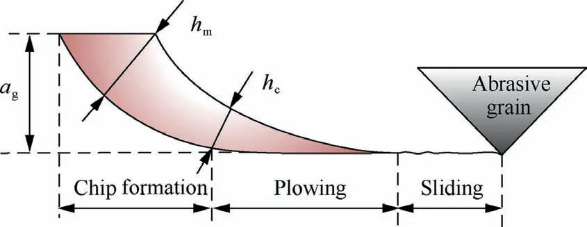
Fig. 1 Schematic diagram of sliding, plowing and chip formation stages.
Commonly,the grinding process contains three stages:sliding, plowing and chip formation. They take place as the abrasive grains begin to cut into the workpiece. In sliding, the elastic deformation begins to occur when the abrasive grains contact the workpiece; in plowing, plastic deformation also occurs with the increase of cutting depth; and in chip formation,the material fractures and the chip is formed with the further increase of the cutting depth, as shown in Fig.1. agis the actual cutting depth of a single grain; hcis the critical undeformed chip thickness and hmis the maximum undeformed chip thickness.
Therefore, the total grinding force F can be written as the sum of sliding force Fsl, plowing force Fpland chip formation force Fch18:

where Ftsl,Ftpland Ftchare the tangential component of sliding force; plowing force and chip formation force and Fnsl, Fnpland Fnchare normal component of them, respectively.
2.1. Sliding force

where δ is the contact area between abrasive grains and workpiece and P-is the average contact pressure between abrasive grains and workpiece.
By approximating the cutting path with a parabolic function,the deviation η which is defined as the difference between the equivalent radius of the abrasive wheel and the radius of curvature of cutting path is expressed as follows18:

where vwis the workpiece infeed speed;vsis the abrasive wheel speed; dsis the diameter of abrasive wheel.
Besides,P-is almost proportional to η and can be expressed as18:
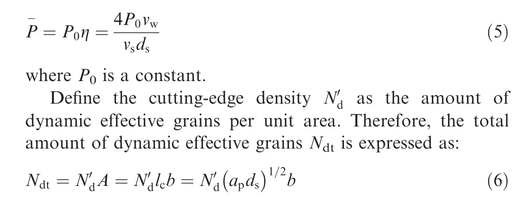
where A is the area of grinding zone;lc=(apds)1/2is the grinding arc length; apis the depth of cut and b is the grinding width.
Because of the nonuniformity of grain height, the number of grains participating in different grinding stages changes.Suppose the proportions of dynamic effective grains in sliding,plowing and chip formation are ξsl, ξpland ξch, respectively.Then the corresponding numbers in these three stages are as follows:

where Ndsl, Ndpland Ndchare the dynamic effective grains in sliding, plowing and chip formation, respectively.
Substitute Eq. (5) into Eq. (3) and multiply by the amount of dynamic effective grains in sliding, Ndsl. Then the normal sliding force Fnslcan be expressed as:

where k1is the physical quantity reflecting the contact state between the workpiece and abrasive grains.
Accordingly, the tangential sliding force Ftslis:

where k2=μ1k1and μ1is the average friction coefficient in sliding. It should be noted that the friction coefficient changes with the variety of the workpiece surface state and performance due to the effect of grinding heat. So the average friction coefficient has been taken for convenience of calculation.
2.2. Plowing force
It has been proposed by Zhang,et al.35that the plowing force is mainly produced by the plastic flow of material. Therefore,owing to the material plastic flow, the average grinding force per unit area Fpis related to the grinding parameters (e.g.abrasive wheel speed vs, workpiece infeed speed vwand depth of cut ap) and some mechanical properties of the material(e.g. modulus of elasticity and yield strength). The schematic diagram of plowing process is displayed in Fig. 2.
The geometrical relationship between Fpand the force in any direction dFxand the plowing force on a single grain distributed perpendicularly to the conical surface were exhibited in Fig. 2(a) and (b), respectively. Then in any direction, force dFxin Fig. 2(b) can be expressed as:

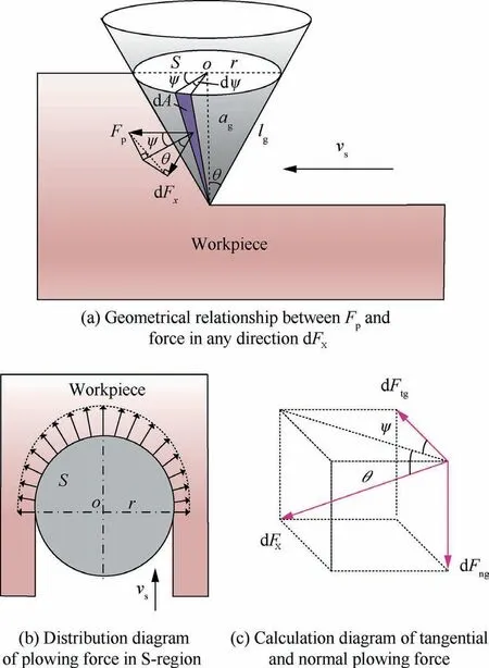
Fig. 2 Schematic diagram of the plowing process of abrasive grain.
with

where dA is the grain-workpiece contact area;r is the radius of S-region; lgis the busbar of the grain-workpiece contact cone and ψ is the angle between any direction and infeed direction.
Then, according to Fig. 2(c) and Eq. (13), the unit tangential plowing force dFtpgand normal plowing force dFnpgacting on a single grain can be calculated as:
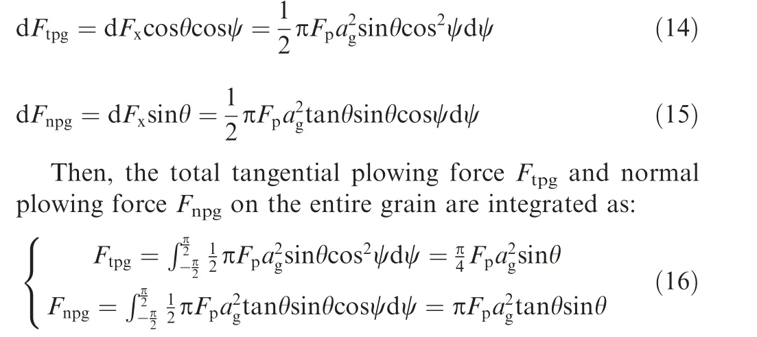
Multiply by the number of dynamic effective grains in plowing (Eq. (7)). Then the tangential and normal plowing forces on the abrasive wheel can be deduced as:
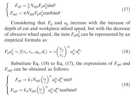
where ε, k3=επ/4 and k4=επ are the constants and α1, α2and α3are the index coefficients.
2.3. Chip formation force
Thespecificgrindingenergyu,whichisusuallydefinedastheenergy expended by removing per unit volume,is expressed as below:

In grinding, the energy consumption also consists of three parts: sliding energy, plowing energy and chip formation energy.Thus according to Eq.(20),the specific chip formation energy uchcan be revised as:

The chip formation stage is also a complex process.43–45However,grinding is a rather complex process with thousands of cutting-edges removing the workpiece material from the micro perspective. Hence to a certain extent, the material removal mechanism during single grain grinding is similar as cutting and milling, which can be considered as shearing removal.So the shear strain effect can also be applied to study the chip formation force in grinding. Meanwhile, it has been announced that the specific chip formation energy mainly consists of the shearing energy during material removal and the cutting-tool friction energy, with proportion of 75% and 25%, respectively.18Then, the relationship between shearing energy and specific chip formation energy is:

where ushis the shearing energy in the material removal process and κ is the constant (usually κ>1).
2.3.1. Shear strain effect of material removal process
In shear deformation, the constitutive relation of dynamic plastic deformation would be expressed as46:

where τ is the shear flow stress; γ is the shear strain; ˙γ is the shear strain rate and T is the material deformation temperature.
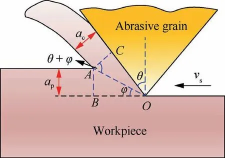
Fig. 3 Schematic diagram of shear deformation in single grain grinding.
As usually, the shear flow stress increases with the increasing of shear strain and shear strain rate, while decreases with the deformation temperature increasing. Then the material shear energy is proportional to the shear rheological stress.The shear deformation diagram during single grain grinding with negative rake angle is shown in Fig. 3.
Based on the theory of cutting deformation,the shear strain and shear strain rate under two-dimensional shear deformation can be expressed as47:

The relationship between shear band thickness Δs1and average undeformed chip thickness acis45:

where λ is constant (6<λ<12); v is the cutting speed and φ is the shear angle.
On the basis of the geometric relation in Fig.2,the thermal deformation coefficient of material χ would be expressed as:

Based on Eqs.(25)and(26),the relationship between shear strain rate and average undeformed chip thickness could be obtained as:

Accordingly, the shear strain rate is in proportion to the abrasive wheel speed vsand in inverse proportion to the average undeformed chip thickness ac. Noted that both acand φ are physical quantities related to grinding parameters and based on the empirical equations,Eq.(29)can be rewritten as:

where k5is a constant;β1,β2and β3are the index coefficients.
2.3.2. Chip formation force calculating
It has been reported that the shear energy is proportional to the logarithm of the shear strain rate, which is expressed as45:
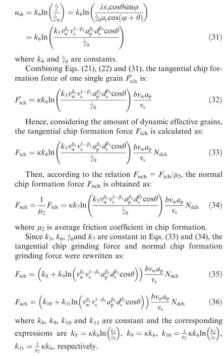
2.4. Development of the grinding force on abrasive wheels
According to the Eqs.(2),(8),(10),(19),(35)and(36),the tangential and normal grinding force can be acquired as:

3. Experimental details
The grinding experiments were carried out on a high-speed surface grinder (BLOHM PROFIMAT MT-408) with maximum abrasive wheel speed of 170 m/s and output power of 45 kW.An electroplated CBN abrasive wheel in width of 10 mm and in diameter of 400 mm was adopted. The abrasive grains were in size of 80#(US mesh).The workpiece material was powder metallurgy nickel-based superalloy FGH96 (similar as the Rene88DT) and the workpiece size was 25 mm×50 mm×5 mm.Chemical compositions and material properties of FGH96 at room temperature are listed in Tables 1 and 2.48The grinding conditions were listed in Table 3.
In order to improve the model precision,orthogonal experiments were usually conducted. In this article, a L25(53)orthogonal experiment was implemented.The grinding parameters, i.e. abrasive wheel speed, workpiece infeed speed and depth of cut, were the three factors and five levels were put to use. The design of orthogonal experiment was listed in Table 4.
A 3-channel piezoelectric dynamometer(KISTLER 9317C)attached with a charge amplifier(KISTLER 5018)was utilized to monitor the grinding force. Measured grinding force signal was received and shown in computer.For improving the accuracy of experimental results, the average grinding force was obtained by measuring it 5 times at each group of parameters.The sampling frequencies in X, Y and Z directions of the dynamometer were 5 kHz, 5 kHz and 20 kHz, respectively. It is generally believed that the grinding force is composed of normal and tangential grinding forces in surface grinding without axial feed.Then,the X and Z directions of the dynamometer were taken to measuring the tangential and normal grinding forces, respectively. The experimental setup was displayed in Fig. 4.

Furthermore,from Eqs.(6)and(7),Eq.(37)can be rewritten as:4. Calculation and validation


Table 1 Chemical composition of FGH96.

Table 2 Mechanical properties of FGH96 at room temperature.

Table 3 Grinding conditions.
4.1. Model calculation
According to the developed grinding force model (Eq. (38)),the established three parts, i.e. sliding force, plowing force and chip formation force, are very complicated. Hence, it is relatively difficult to solve the unknown coefficients in Eq.(38)directly.Additionally,it has been reported that the sliding force, plowing force and chip formation force share different proportions of the total grinding force.41Hence, for the sake of improving the exactitude of the proposed model in this article, the subsection calculation method has been exploited to solve the unknown coefficients of the model. In other words,the measured grinding forces have been divided into three sections in different proportion and the unknown coefficients were calculated and optimized by linear regression. Considering the count of unknown coefficients, ten groups of experimental results have been randomly chosen to solve the coefficients, as listed in Table 5. The calculated results of the coefficients are listed in Table 6.Accordingly,the final expression of the grinding force is shown in Eq. (39).

Table 4 Design of orthogonal experiment.
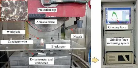
Fig. 4 Experimental setup.

4.2. Validation and analysis
The comparison between predicted and remaining experimental results are listed in Table 7 for validation. The average errors of tangential grinding force and normal grinding force are 9.8% and 13.6%, respectively. The results indicate that the predicted results agree with the experimental results very well.
Furthermore, on the basis of the final expression of grinding force (Eq. (39)), the contribution of these three components to the total grinding force are analyzed, as listed in Table 8. For tangential force, the average proportions of the forces of sliding, plowing and chip formation are about 64%, 22% and 14%, respectively; and for normal force, the proportions turn to 66%, 17% and 17% with little difference.It is noted that the proportion of sliding force on the total grinding force is much bigger than that of plowing force andchip formation force,approximately 3 times.This finding indicates that sliding dominates the grinding process, which aggresses with the reported results in Refs. 35,41.

Table 5 Ten experimental results using for computing unknown coefficients.

Table 6 Coefficient values of grinding force model.
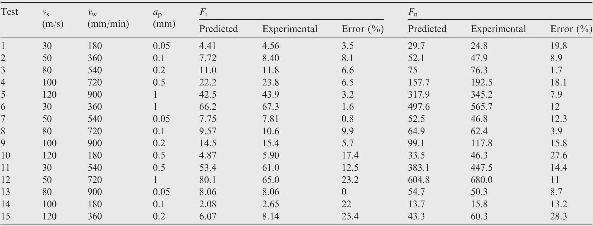
Table 7 Comparison between predicted and experimental results.
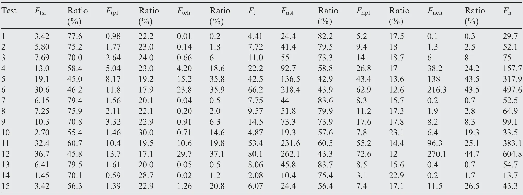
Table 8 Contribution of sliding, plowing and chip formation force to total grinding force.
In addition,the tangential forces of sliding and chip formation are 14%and 11%of the normal forces on average according to Table 8,respectively.While the tangential plowing force is 19% of normal plowing force. Obviously, the force ratio of plowing is the highest in the three stages.This is likely because of the thermal-softening effect on the workpiece material in plastic deformation.
The grinding force model is developed based on material removal process of grinding option in micro aspect. Hence,the established model can be theoretically applied to the grinding force prediction of metal materials under different working conditions (e.g. coolant, metal material and abrasive wheels).From Eq. (38), the grinding forces under different working conditions can be predicted if the unknown coefficients are obtained.Then preliminary experiments are essential for calculating the unknown coefficients.
5. Conclusion
(1) The grinding force model was developed by considering the mechanism of sliding, plowing and chip formation during grinding. The contributions of tangential and normal sliding force on the total grinding force were about 64%and 66%on average,while the contributions of tangential and normal plowing were about 22% and 17%, and the contributions of tangential and normal chip formation force were 14% and 17%, respectively.
(2) The tangential forces of sliding and chip formation are 14% and 11% of the normal forces on average, respectively.While the tangential plowing force is 19%of normal plowing force because of the plastic deformation of FGH96 material.
(3) The grinding force model was validated by the orthogonal grinding experiment of powder metallurgy nickelbase superalloy FGH96 by using electroplated CBN abrasive wheel. The predicted forces were in agreement with the experimental ones. The errors of tangential grinding force and normal grinding force were 9.8%and 13.6%, respectively.
Acknowledgments
The authors gratefully acknowledge the financial support for this work by the National Natural Science Foundation of China (Nos. 51775275, 51921003 and 51905363), the Funding for Outstanding Doctoral Dissertation in NUAA of China(No. BCXJ19-06), the Natural Science Foundation of Jiangsu Province of China(No.BK20190940),and the Natural Science Foundation of the Jiangsu Higher Education Institutions of China (No. 19KJB460008).
 CHINESE JOURNAL OF AERONAUTICS2021年8期
- CHINESE JOURNAL OF AERONAUTICS的其它文章
- A novel virtual material layer model for predicting natural frequencies of composite bolted joints
- Multi-layered plate finite element models with node-dependent kinematics for smart structures with piezoelectric components
- Modeling bending behavior of shape memory alloy wire-reinforced composites: Semi-analytical model and finite element analysis
- Sequential ensemble optimization based on general surrogate model prediction variance and its application on engine acceleration schedule design
- Transition prediction and sensitivity analysis for a natural laminar flow wing glove flight experiment
- Modeling on mechanical behavior and damage evolution of single-lap bolted composite interference-fit joints under thermal effects
