Constrained layer damping treatment of a model support sting
Jiahao PAN, Zhanqiang LIU,*, Xiping KOU, Qinghua SONG
a School of Mechanical Engineering, Shandong University, Ji’nan 250061, China
b Key National Demonstration Center for Experimental Mechanical Engineering Education/Key Laboratory of High Efficiency and Clean Mechanical Manufacture of MOE, Ji’nan 250061, China
c High Speed Aerodynamics Institute, China Aerodynamics Research and Development Center, Mianyang 621000, China
KEYWORDS Constrained layer damping;Model supports;Vibration control;Viscoelastic materials;Wind tunnels
Abstract In transonic wind tunnel tests,the pulsating airflow is prone to induce the first order resonance of the sting support system. The resonance limits the wind tunnel test envelope, makes the test data inaccurate, and brings potential security risks. In this paper, a model support sting with constrained layer damping (CLD) treatment is proposed to reduce the first order resonance response.The CLD treatment mainly consists of material selection and geometric optimization processes.The damping performance of the optimized CLD sting is compared with an AISI 1045 steel sting with the identical diameter in laboratory.The frequency response curves of the CLD sting support system and the AISI 1045 steel sting support system are obtained by sine sweep tests.The test results show that the first order resonance response of the CLD sting support system is 37.3% of that of the AISI 1045 steel sting support system.The first order damping ratios are calculated from the frequency response curves by half power point method.It is found that the first order damping ratio of the CLD sting support system is approximately 2.6 times that of the AISI 1045 steel sting support system.
1. Introduction
During wind tunnel testing, the aircraft model is usually installed in the test section by sting support system. The sting support system is a typical cantilever system. Considering the interference to the flow field, the model support sting is designed to be slender. The sting support system has low stiffness and low damping characteristics. The first order resonance problem is prone to occur under the excitation of the unsteady aerodynamic loads.1The resonance problem of the sting support system limits the range of test parameters such as angle of attack,Mach number,and velocity pressure,which results in failure to obtain enough data for the aircraft design.The resonance interferes with the measurement of force balance and attack angle sensor, which affects the accuracy of the test data.2In addition, the resonance may cause a severe overload of the balance and therefore damage the balance.Once the sting is broken by the resonance, the model and the wind tunnel will be damaged,which causes serious security issues and economic losses. It is necessary to study the vibration reduction measures with good effect and high reliability.
Although reducing the pulsating airflow in the test section can attenuate the vibration of the sting support system, this involves the improvement to the wind tunnel. However, the improvement of wind tunnel is time consuming and costly.3,4The vibration can be reduced by increasing system stiffness.C´ urcˇic´ et al.replaced the central cylindrical part of the existed sting with a core made of WC-Co alloy. WC-Co alloy could increase the stiffness of the sting by 30%.5However, the WC-Co alloy is hard to machine due to its high hardness.
Another way to mitigate the resonance is to increase system damping. Igoe and Capone proposed a tuned mass damper installed in the aircraft model.6Freymann designed a dynamic damper mounted inside the sting.7The dampers could reduce the resonance response by approximately 50%when they were properly tuned. However, the changes in the pulsation frequency of the airflow degraded the performance of the dampers. In addition, the dampers required large installation space in the model, which limited the applications of tuned mass dampers. Fuykschot and Kooi introduced damping to the system by using spring washers. The spring washers were installed between the sting and the angle of attack adjusting mechanism. This method was versatile and could dissipate about 30%of the energy.8Glaese et al.developed a hub damper unit to increase passive damping. The hub damper buried the viscoelastic material within the sting adapter. It could reduce the vibration by up to 30%.9
With the development of smart materials,some researchers have focused on active dampers. The active dampers can suppress the vibration of the sting support system. The vibration signals are detected by sensors, and the actuators made of smart materials are controlled to counteract the vibration.Fehren et al. proposed an active damper installed between the sting and the balance in the European Transonic Wind Tunnel. The active damper was actuated by 14 piezoelectric ceramics.10Balakrishna et al.developed an active damper with 12 piezoelectric stacks mounted between two sting segments.11These active dampers could reduce the vibration by more than 70%.Liu et al.increased the damping effect of the active damper to more than 90% by adopting adaptive fuzzy control algorithm.12Due to its excellent performance, the active damper has become a main solution to the vibration problem of the sting support system. However, the active damper relies on external energy. Once the external energy supply is suddenly interrupted during the test, the active damper will no longer function and the uncontrolled vibration may damage the wind tunnel test equipment. The operation of the active damper depends on sensors. The sensor faults may result in incorrect output of the active damper, which will exacerbate the vibration. Moreover, the development and maintenance costs of the active vibration control system are high. Therefore, it is of great significance to develop passive auxiliary measures with high reliability, good effect and low cost.
Constrained layer damping(CLD)treatment is a method to increase system damping based on the shear energy dissipation mechanism of viscoelastic materials. Kerwin proposed a complex stiffness method to analyze the damping effectiveness of CLD structures.13Ungar and Kerwin developed an accurate and intuitive analytical model from the perspective of energy.14,15In recent years, CLD treatment has been widely used in vibration control in various industrial fields.In the field of manufacturing,Liu et al.developed CLD treatment on tool holders.The CLD boring bar could reduce the radial vibration by more than 50%.16,17The CLD milling arbor showed a considerable increase in dynamic stiffness,which was about 600%higher than that of the traditional milling arbor.18In the field of aeronautics and astronautics,Gao et al.used the CLD treatment to mitigate the vibration of the aerospace pipeline and investigated the influence of structural parameters on the damping performance.19Luo et al. attenuated the dynamic response of the spatial truss structure by using CLD long tubes, thereby ensuring the normal operation of the optoelectronic equipment in the space station.20In the field of civil engineering, Kliem et al. applied the CLD treatment to the design of composite power pylon and up to 106.3%additional damping was obtained.21These applications have demonstrated the excellent effectiveness and reliability of the CLD treatment in vibration dissipation.
The CLD treatment is more economical to solve the resonance problem of the sting support system. A large number of existing stings can be improved by CLD treatment to meet the requirements of transonic wind tunnel test. In this paper,the feasibility of the CLD treatment on the cantilever sting is investigated. The remainder of this paper is organized as follows. Firstly, the original sting and the CLD structure are introduced in Section 2. Then, the material selection and geometric optimization processes are described in Section 3.After that, the tests for verifying the damping performance of the proposed CLD sting are presented in Section 4. Finally, some conclusions are drawn in Section 5.
2. CLD treatment
2.1. Original sting support system
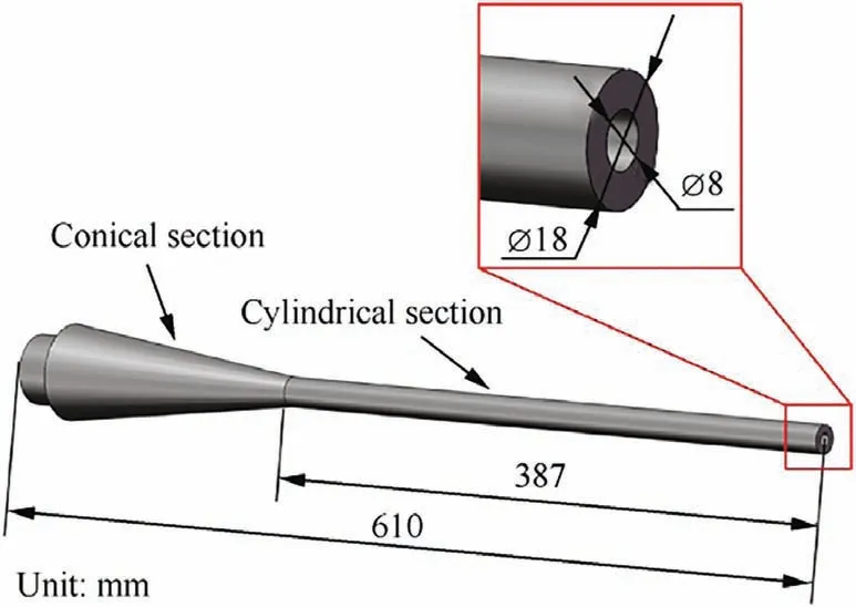
Fig. 1 Schematic diagram of the original sting.
The sting support system is mainly composed of a cantilever sting and a model installed at the free end of the sting. In this study, the original sting made of AISI 1045 steel (610 mm in length)consists of a cylindrical section and a conical section,as shown in Fig. 1. The length of the cylindrical section is 387 mm,with an outer diameter of 18 mm and an inner diameter of 8 mm. The conical section is used for fixation. The vibration of the conical section can be negligible due to it is approximated as a rigid body.
The modal analysis of the original sting support system was conducted by using finite element method. To simplify the analysis, the aircraft model has been replaced by a weight of 3 kg. A fixed constraint was applied at the conical section of the sting. The result of the finite element analysis is presented in Fig. 2.
The first order natural frequency obtained from the finite element analysis was 19 Hz, which was close to the previous wind tunnel test results. The errors caused by regarding the conical section as a rigid body and replacing the model with a weight could be acceptable in this research.
2.2. CLD structure
The damping effect of the CLD structure comes from the internal friction of the damping layer.When the structure vibrates,the tensile and compressive deformations occur inside the damping layer. The deformation of the constraining layer is much smaller than that of the damping layer,the constraining layer hinders the deformation of the damping layer, which results in a large shear deformation inside the damping layer.Most of the vibrational energy is dissipated by the shear deformation.
The proposed CLD sting mainly consisted of three parts,the substrate (part of the cylindrical section of the original sting),the damping layer and the constraining layer,as shown in Fig.3.The CLD treatment was performed on the cylindrical section and the length of the treated section was 320 mm. The damping layer was made of viscoelastic material and then covered with an AISI 1045 steel constraining layer.The untreated section of the free end was for the model installation.To avoid the stress concentration caused by variable section,the conical section was turned to ensure the smooth transition of the section.
The structural loss factor is an index to evaluate the damping effectiveness of the CLD structure. In Ref.14, Ungar and Kerwin defined the structural loss factor η from the perspective of energy as

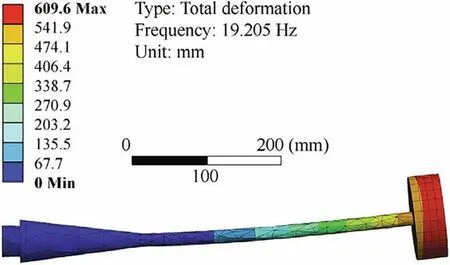
Fig. 2 Result of finite element analysis.
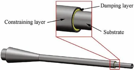
Fig. 3 Conceptual scheme of CLD sting.
where D is the vibration energy dissipated by the CLD structure per cycle and W is the total mechanical energy of the system during vibration.
The expression of structural loss factor of general CLD structure related to material parameters and geometric parameters was derived in Ref.15as
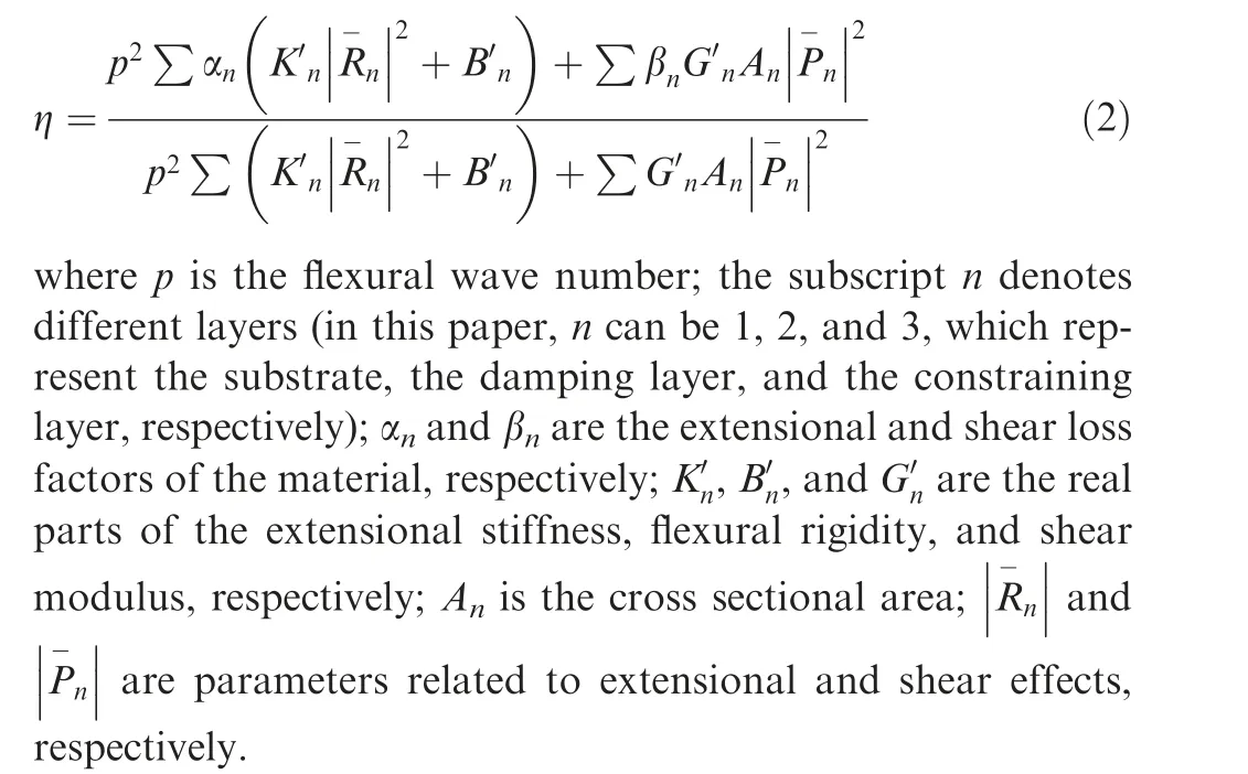
Due to the damping effect of the CLD structure mainly coming from the shear energy dissipation of the damping layer material,Ungar ignored the extensional and shear losses of the substrate as well as the constraining layer, the simplified expression of the structural loss factor was obtained as15
3. Optimal design of CLD sting
3.1. Material selection of damping layer
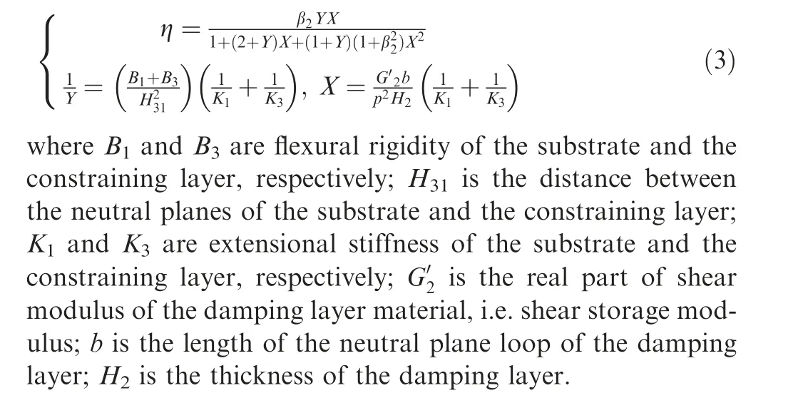
To obtain the excellent damping effect, the viscoelastic material of the damping layer was optimally selected.It can be seen from Eq. (3) that the structural loss factor is related to two characteristics of the damping layer material,i.e.the shear loss factor β2and the shear storage modulus
Three candidate viscoelastic materials including chloroprene rubber (CR), nitrile butadiene rubber (NBR), and polyurethane (PU) were compared in this research. To obtain the shear loss factor and the shear storage modulus of these materials,the materials were fabricated into samples with specification of 10 mm×10 mm×4 mm.The samples were tested in a dynamic mechanical analyzer (DMA Q800) at 25°C. During tests,the samples were excited with the sinusoidal stress of constant amplitude. The resultant sinusoidal strain and the phase difference between the stress and strain were measured. The vibration problem of the sting support system is mainly the first order resonance. The frequency range of the dynamic mechanical test was therefore set up to 1–50 Hz. The complex shear modulus is equal to the ratio of the shear stress to shear strain. Shear loss modulus and shear storage modulus are the imaginary and real parts of the complex shear modulus,respectively. The ratio between them is called the shear loss factor, i.e. the tangent of the phase difference. The shear loss factor and shear storage modulus of the three viscoelastic materials obtained from the dynamic mechanical test are shown in Fig. 4.
To select the most suitable material, the effect of the material loss factor β2on the structural loss factor η needs to be determined. The partial derivative of η with respect to β2can be derived from Eq. (3) as
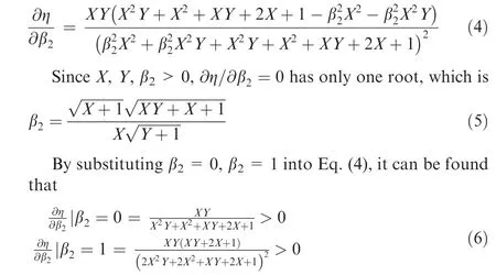
This means that when 0<β2<1, ∂η/∂β2>0, i.e. η increases with β2. Therefore, PU was the most suitable material for the damping layer among the three materials. Moreover, it was noticed that PU had the lowest shear storage modulus, which was conducive to large shear deformation and thus increased energy dissipation. The PU material used in this research was provided by YINGJIADA. At 25°C and 30 Hz, the shear storage modulus and Young’s modulus were 13 MPa and 41 MPa, respectively. The density was 1210 kg/m3and the shear loss factor was 0.5.
3.2. Geometric parameter optimization
After selecting PU as the material of the damping layer, the CLD sting was geometrically optimized to minimize the first order resonance amplitude of the sting support system.Assuming that the vibration is harmonic, the first order resonance amplitude x can be expressed as22

where F is the amplitude of the exciting force; Ksis the static stiffness of the CLD sting, which can be expressed as

where B is the flexural rigidity,and in this paper,it refers to the sum of the flexural rigidity of each layer;l denotes the length of the cantilever structure. It can be seen from Eq. (7) that the optimization objective can be transformed into the maximum of the product of the first order structural loss factor and the static stiffness (ηKs).
Note that to avoid excessive interference to the flow field,the outer diameter of the cylindrical section of the CLD sting was limited to 25 mm.The geometric optimization was thus to determine the thickness of the damping layer, i.e. H2mentioned in the previous analysis. The dimensions of the substrate, damping layer and constraining layer are shown in Table 1.
According to Eqs.(3)and(8),the influence of the thickness of the damping layer on the first order structural loss factor,static stiffness,and the product of the first order structural loss factor and the static stiffness can be obtained, as shown in Fig. 5.
It can be seen from Fig. 5(a) that the first order structural loss factor increased initially with the damping layer thickness.However, the first order structural loss factor decreased when the damping layer thickness was greater than 2.9 mm in this research. In addition, Fig. 5(b) shows that the static stiffness decreased with the damping layer thickness. The product of the first order structural loss factor and the static stiffness was up to its maximum when the damping layer thickness was 1.9 mm, as shown in Fig. 5(c). The thickness of the damping layer was therefore determined to be 1.9 mm. The dimensions for the optimized CLD sting are shown in Table 2.
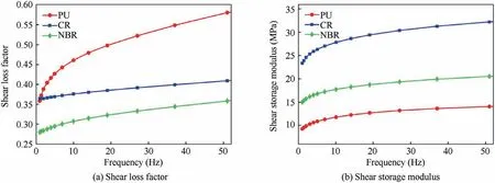
Fig. 4 Shear loss factor and shear storage modulus of three viscoelastic materials.

Table 1 Dimensions of the substrate, damping layer, and constraining layer.
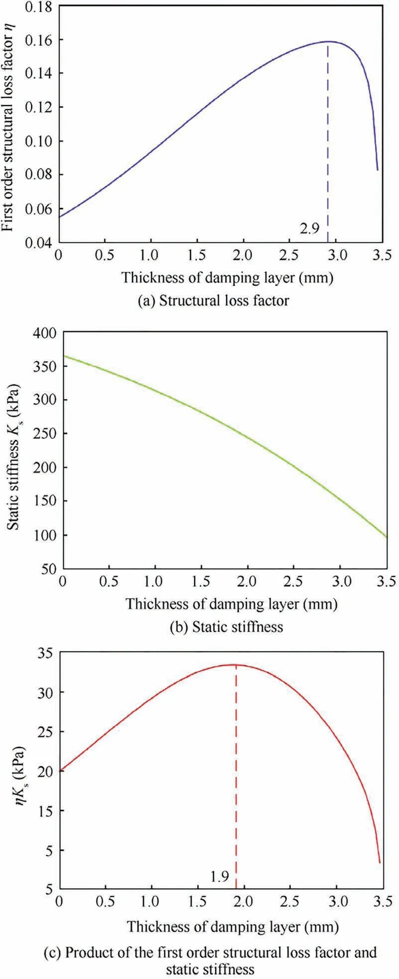
Fig. 5 Influence of damping layer thickness.
To facilitate the test verification, the first order structural loss factor η was converted into first order damping ratio ς that could be easily measured. According to Ref.22, the damping ratio was half of the structural loss factor. As shown in Fig. 5(a), when the damping layer thickness was 1.9 mm, the theoretical first order structural loss factor was 0.13, and the theoretical first order damping ratio was 0.065. When the damping layer thickness was 0,the theoretical first order structural loss factor was 0.05,and the theoretical first order damping ratio was 0.025. The damping layer thickness with 0 corresponds to a special situation, i.e., the steel sting with the identical diameter as the CLD sting.
Although the static stiffness of the CLD sting was lower than that of the steel sting with identical diameter, CLD sting had greatly higher first order structural loss factor. The CLD sting had higher product of the static stiffness and the first order structural loss factor, which meant that it would take lower resonance response. Therefore, the performance of CLD sting would be advanced comparing with that of the steel sting.
4. Test verification
After optimization design, CLD treatment was conducted on the original sting. The CLD treatment increased the diameter of the sting, which subsequently increased the stiffness and improved the capability of vibration resistance. It was meaningless to compare the vibration reduction ability of the proposed CLD sting with the original sting. Instead, an AISI 1045 steel sting with the identical diameter as the CLD sting was manufactured for comparison, as shown in Fig. 6.
The verification tests were carried out in laboratory to determine the effective performance of CLD sting.The aircraft model was replaced by a 3 kg weight and the weight was supported by the sting.Another end of the sting was fixed by a fixture.The frequency response curves of the CLD sting support system and the AISI 1045 steel sting support system were obtained through sine sweep tests. The first order damping ratios were estimated from the frequency response curves by half power point method. The sine sweep test platform was composed of a signal generator (DH1301), an exciter(DH40020), an accelerometer (DYTRAN 3035B), and a data acquisition card (PXIe-4464), as shown in Fig. 7.
The signal generator was set up to the sine sweep mode,the start and the termination frequencies were adjusted to 1 Hz and 50 Hz, respectively. The sweep rate was set up to 1 Hz/s.The sting support system was excited with the sinusoidal force of constant amplitude and the vibration response of the sting support system was measured by the accelerometer.The acceleration signal was then collected by the data acquisition card and analyzed by the signal analysis software (SignalPad).The frequency response curves of the two sting support systems are shown in Fig. 8.

Table 2 Dimensions for the optimized CLD sting.
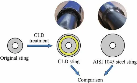
Fig. 6 CLD sting and AISI 1045 steel sting.
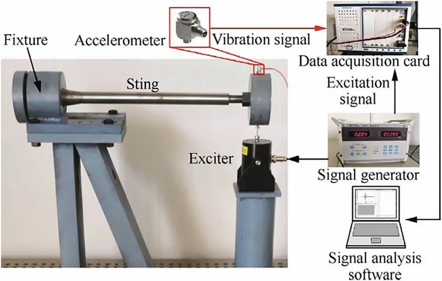
Fig. 7 Sine sweep test platform.
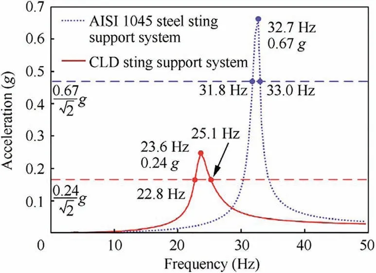
Fig. 8 Sine sweep test results.
It can be seen from Fig. 8 that the first order resonance amplitude of the AISI 1045 steel sting support system was 0.67 g, while that of the CLD sting support system was 0.24 g. The first order resonance response of the CLD sting support system was 37.3% of that of the AISI 1045 steel sting support system. In addition, the first order damping ratios of the support system with CLD sting and AISI 1045 steel sting could be obtained from Fig. 8 by half power point method.
The half power point refers to the corresponding points of the 1/√---2of the resonance amplitude on the frequency response curve and the damping ratio ς can be calculated as22


Table 3 Theoretical and experimental values of damping ratios.
where ωh2and ωh1are frequencies of half power point 2 and half power point 1, respectively, and ωh2>ωh1; ωris the resonance frequency.
The first order damping ratio of the CLD sting support system was 0.049 according to Eq.(9)and Fig.8.It was 0.018 for that of the 1045 steel sting support system. Both the experimental first order damping ratios and the theoretical values calculated in Section 3.2 are listed in Table 3.
It can be seen from Table 3 that the experimental and theoretical values were in good agreement. The first order damping ratio of the CLD sting support system was approximately 2.6 times that of the AISI 1045 steel sting support system,which verified that the CLD treatment could considerably increase damping of the wind tunnel sting support system.Although the static stiffness of the CLD sting support system was slightly lower than that of the AISI 1045 steel sting support system, CLD sting support system still had higher dynamic stiffness, which could be reflected by its lower resonance response. Thus, the CLD sting had better vibration resistance capability than the AISI 1045 steel sting did.
5. Conclusions
In this study, the CLD treatment of the model support sting has been proposed, which consisted of the process of material selection and geometric optimization. The vibration dissipation capability of the optimized CLD sting was tested in laboratory and compared with an AISI 1045 steel sting with the identical diameter. The frequency response curves of the CLD sting support system and the AISI 1045 steel sting support system were obtained by sine sweep tests. In addition,the first order damping ratios of the two systems were calculated from the frequency response curves by half power point method. Several conclusions are summarized as follows.
(1) When the shear loss factor of the damping layer material was greater than zero and less than 1,the structural loss factor of the CLD sting increased with the shear loss factor.
(2) When the product of the first order structural loss factor and static stiffness was in the maximum value, the first order resonance amplitude of the system could be the minimum.
(3) Both the theoretical and experimental results showed that the first order damping ratio of the proposed CLD sting support system was approximately 2.6 times that of the equivalent diameter AISI 1045 steel sting support system.
(4) The great increase in damping compensated for the slight decrease in static stiffness. The dynamic stiffness of the system still increased. The vibration resistance capability of the CLD sting support system was better than that of the AISI 1045 steel sting support system.
Acknowledgement
This work was supported by Fenglei Youth Innovation Fund of China Aerodynamics Research & Development Center(PJD20180189) and Shandong Provincial Natural Science Foundation of China (2019JMRH0307). This work was also supported by grants from Shandong University and Taishan Scholar Foundation.
 CHINESE JOURNAL OF AERONAUTICS2021年8期
- CHINESE JOURNAL OF AERONAUTICS的其它文章
- A novel virtual material layer model for predicting natural frequencies of composite bolted joints
- Multi-layered plate finite element models with node-dependent kinematics for smart structures with piezoelectric components
- Modeling bending behavior of shape memory alloy wire-reinforced composites: Semi-analytical model and finite element analysis
- Sequential ensemble optimization based on general surrogate model prediction variance and its application on engine acceleration schedule design
- Transition prediction and sensitivity analysis for a natural laminar flow wing glove flight experiment
- Modeling on mechanical behavior and damage evolution of single-lap bolted composite interference-fit joints under thermal effects
