Influence of laser shock peening on surface integrity and tensile property of high strength low alloy steel
Yong WANG,Xiaoyu PAN,Xibin WANG,Zhibing LIU,Shuyao LIU,Wenjuan WAN,Puyi WANG
School of Mechanical Engineering,Beijing Institute of Technology,Beijing 100081,China
KEYWORDS
Abstract Laser Shock Peening(LSP)is a well-established surface treatment commonly used to improve mechanical properties of material’s surfaces.To further understand the relationship between tensile property and fatigue life improvement of high strength low alloy steel in the LSP process,LSP treatment of 32CrNi high strength low alloy steel was carried out by YAG laser with pulse energy of 15 J,and tensile property was tested by electronic universal material testing machine.Surface morphology,residual stress and tensile fracture of the specimens before and after LSP were observed by white light interferometer(WLI),X-ray measuring apparatus and scanning electron microscope(SEM).Result shows that LSP did not change tensile strength of 32CrNi steel but cause yield characteristic transform from obvious yield point to no yield phenomenon which is the only factor benefiting fatigue life,indicating that the increment of fatigue life was probably related to the disappearance of yield phenomenon.Formation mechanisms of tensile fractures and yield phenomenon induced by LSP at room temperature were also discussed and completely revealed.Deeper compressive residual stress and flat grains contributed to the transition of yield characteristic and lower elongation rate of 32CrNi steel subjected to LSP.
1.Introduction
High strength low alloy steels have been used as aviation materials such as aircraft landing gears due to their qualified impact toughness,ultrahigh strength,and excellent weldability.1-3In actual engineering applications,the mechanical properties of 32CrNi high strength low alloy steels are still urgent to be improved to bear bigger impact load affected directly by operating environment.Some studies have shown that mechanical properties of materials can been improved by using traditional surface treatment to change surface integrity,such as accumulative roll bonding,4high-energy shot peening,5surface mechanical attrition treatment,6and ultrasonic shot peening.7
Laser shock peening(LSP)is a well-established surface treatment technology,and it can effectively improve mechanical and fatigue properties with laser shock wave introducing significant compressive stress and refine coarse grains of metallic components.8-10Compared with these conventional surface treatments,LSP has three remarkable advantages including controllable heat source,small heat distortion,and good geometric adaptability.11,12For example,Lu and his colleagues13studied the effects of LSP on tensile properties and surface microstructure of H62 brass with different coverage layers at room temperature.They found that the nanostructured surface with an average depth of less than10 nm generated by LSP improved ultimate tensile strength and elongation rate of H62 brass.Furthermore,they subsequently characterized ultimate tensile strength,elongation rate,and in-depth microstructural evolutions of three kinds of the LSPed specimens and revealed the formation mechanisms of surface nanocrystallization and amorphization induced by LSP.Li et al.14analyzed the effect of the cryogenic LSP on tensile properties and microstructural response of 2024-T351 aluminum alloy specimens,and results indicated that higherdensity of dislocation and smaller-size grain induced by cryogenic laser peening can lead to higher strength,plasticity strength and plasticity,and the excellent tensile properties were beneficial to microstructural evolution induced by cryogenic laser peening.In addition,Lu et al.15explored the effect of LSP at different service temperature on tensile properties and microstructural evolution of CP titanium,and results showed that the higher service temperature were attributed to the bigger elongation and area reduction of the LSPed specimens.However,the ultimate tensile strength decreased.Furthermore,they also found that ultra-high strain rate was more likely to activate dislocation movement at a higher temperature so that the deformation twins in CP titanium plastic deformation layer disappear.Sun et al.16explored the effect of laser shock peening on tensile properties,residual stress and microstructure control of wire-arc additive manufactured 2319 aluminum alloy,and they found that high density of dislocations and mechanical twins induced by LSP resulted in the increase of micro-hardness.Furthermore,LSP made residual stresses transform from tensile to compressive stress and made yield strength remarkably increased.From above open literature,it is believed that tensile property of metallic materials always results from micro-plastic deformation with residual stress changing.17,18It is well known19that LSP can induce ultrahigh-strain-rate plastic deformation beneficial to fatigue life.Further,fatigue life improvement of 32CrNi steel induced by LSP was noticed in our recent investigations.20However,the effect of tensile property of 32CrNi steel for fatigue life improvement in the LSP process was not clear in previous publications,and there are also some differences about tensile property induced by LSP for specific materials.In this paper,influence of laser shock peening on surface integrity and tensile property of 32CrNi steel were studied.Fracture morphologies of tensile specimens were observed,and the relationship between surface integrity(such as residual stress,surface morphology)and tensile properties was analyzed.It provides a reference for improving mechanical properties of 32CrNi steel by laser shock peening.
2.Experiment
2.1.Material and specimen preparation
All tensile specimens were cut from a solid cylinder with the diameter of 170 mm in the present study.Their dimensions were shown in Fig.1 and chemistry property was given in Table 1.Prior to the LSP treatment,SiC paper of different roughness grades were used to polish the circumferential marks of cylindrical surface caused by finish turning.Then,tensile specimens were washed with deionized water.Finally,these specimens were immersed in acetone to get the degreased surfaces by ultrasound wave.
2.2.Laser shock peening experiments
LSP experiments were conducted by using a Q-switched Nd:YAG laser,and its wavelength is 1064 nm.In the LSP process,parameters were set in the experiment,e.g:a pulse width of 20 ns,a laser beam with a diameter of 3 mm,a pulse energy of 15 J and the repetition rate of 2 Hz.As is shown in Fig.2,a professional aluminum foil(thickness of 0.12 mm)is used as an absorbent coating to avoid laser ablation and melting on the metal surface,and the deionized water is used as a transparent confinement layer(with thickness of about 2 mm)to increase the intensity of shock waves propagated into the specimens.12,19,21The tensile specimens were clamped on a six-axis manipulator fixture which can realize system rotation,and massive LSP treatment was applied from the upper point of the specimens(red point)to the bottom point in sequence,as shown in Fig.2.The tensile specimens rotate 45°when a circumferential shock of the laser was completed,and circumferential laser shock was finished 8 times with the manipulator driving the specimen to move down 1.5 mm for axial laser shock.The overlapping rates remained at 50% in the circumferential and longitudinal directions.
2.3.Measurement method
Surface morphology of the specimens were measured with the use of a white light interferometer(CCILITE M112)with Zaxis measurement accuracy of 0.01 nm.And measurements were made on each specimen at different areas by utilizing the relationship between the light intensity and the optical path difference to obtain the 3D topography of the measured object.Microhardness was measured by using a diamond tip indenter(HXS-1000A,china)with a test load of 25 g and a dwell period of 10 s.It was measured from the peened surface to a depth with 1.1 mm with a step distance of 0.05 mm.Electron back scattered diffraction(EBSD)analysis was carried out with the use of a Zeiss Sigma 500 scanning electron microscopy(SEM)system.
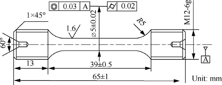
Fig.1 Dimension of specimens for tensile tests.

Table 1 Chemical components of 32CrNi steel(wt%).
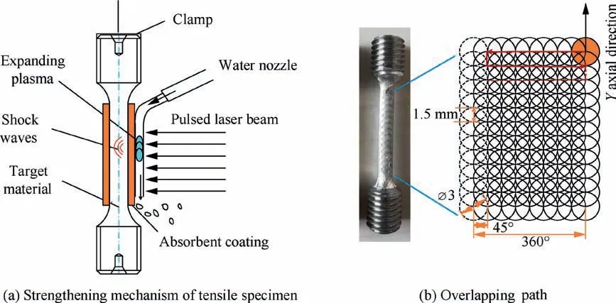
Fig.2 Schematic representation of laser shock peening.
Residual stress measurements were carried out with an Xray Stress Analyzer(X-350A,produced by Astor)with the use of Cr-Kαrays by tracking the(2 1 1)peak of theαphase,and the standard sin2Ψmethod was used to measure the Full Width at Half Maximum(FWHM)values.Electrolytic layer removal method was conducted to analyze residual stresses in two orthogonal directions of different depth.The two directions will be denoted as x direction(circumferential direction)and y direction(axial direction)for the simplicity of data analysis,and residual stresses at different depths were measured with the use of electro-polishing layer by layer.The layer removal size was 15μm at the first 150μm depth to get more detailed stress information of subsurface.Then the spacing increases to 100μm as the depth increases.Electro-polishing was operated with 80 % methanol and 20% perchloric acid and at a voltage of 26 V.Tensile properties of the baseline specimens and LSPed specimens were measured with the use of a Instron-5958 electronic universal testing machine,where the tensile strain rate was 1×10⁻³s-1and the load rate was 1 mm/min in this tensile test.To reduce random errors,the specimens before and after LSP were carried out three times.After the tensile tests,the pars fibrosa,radiation zone and shear lip zone of the tensile fracture morphology were also observed and analyzed in detail by using a JCM-7000 tungsten filament SEM.
3.Results and discussion
3.1.Surface morphology
Surface morphology measured by white light interferometer is shown in Fig.3.It is clear that surface roughness Raand Rzof the baseline specimens are 1.263μm,9.303μm respectively,and surface roughness Raand Rzof the LSPed specimens are 2.138μm,13.401μm respectively.Surface roughness of LSPed specimens increases.In the LSP process,the shock waves induced by laser cause large plastic deformation on the surface,resulting in higher dislocation pile-ups in the surface,as shown in Fig.3(b).There are a higher peak and lower valley(Fig.3(c))on the surface of the LSPed specimens compared with baseline specimens(Fig.3(d)).As shown in cloud diagrams of surface morphology,there are also obvious pits and overlap marks(Fig.3(d))on the surface of the LSPed specimens,resulting from surface roughness of the LSPed specimens on the surface increases obviously compared with that of baseline specimens.Uneven energy distribution of laser spot on the surface on the surface makes inhomogeneous plastic deformation(pits).
3.2.Residual stress
Residual stress results are shown in Fig.4,and Fig.4(b)as illustrated in corresponding magnified view of the shaded part of Fig.4(a).As shown in axial direction(in Y direction)of Fig.4(a),the compressive residual stress of the baseline specimens on the surface(black curve)is close to-124 MPa and gradually tends to zero passing the depth of 34μm.It is attributed to finished polishing process at sample preparation stage.Compared with the baseline specimens,LSP introduces a deeper and larger compressive residual stress.The LSPed specimens exhibits a large compressive residual stress of-314 MPa(blue curve in Fig.4(a)and(b))on the surface.It is because that shock wave generated in the LSP process causes large residual stress.As the depth increases(blue curve in Fig.4(a)and(b)),compressive residual stress of the LSPed specimens shows a spoon shape,and many literatures about LSP have come to similar conclusions.22,23The compressive residual stress first reaches a maximum value of-441 MPa at the depth of 126μm,and compressive residual stress finally transforms into tensile residual stress passing the depth of 903μm.Residual stress in circumferential direction(in X direction)on radial depth direction before and after LSP changes rarely.Compressive residual stress in circumferential direction(in X direction)is obviously smaller than that in axial direction.The most likely reason is that the material is more difficult to undergo larger plastic deformation in the circumferential direction due to the smaller radius of curvature compared with the infinite radius of curvature in the axial direction.It can be seen from Fig.4(b)that the LSPed specimens exhibits compressive residual stress of-85 MPa within the depths of 35-100μm relative to the baseline specimens.
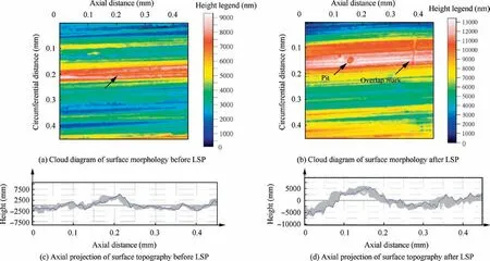
Fig.3 Surface morphology before and after laser shock peening.
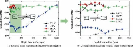
Fig.4 Residual stress before and after LSP.
3.3.Microhardness of radial depths direction
Microhardness of the material is an important indicator of mechanical property,which reflects effects of dislocation density and crystal structure change induced by LSP,with results shown in Fig.5.Microhardness of the baseline specimens shows the largest value on the surface due to the specimen preparation,where the maximum hardness is 362 HV0.025and the depth of influence is 250μm.To the LSPed specimens,plastic deformation induced by shock waves causes a higher dislocation density,which in turn produces a large hardness value,and we can see from blue curve that the surface of the LSPed specimens has a higher microhardness of 405 HV0.025and the depth of influence is 700μm.The microhardness of the sample with axial polishing also shows a tendency to gradually decrease and the maximum hardness is 405 HV0.025on the surface.It should be noted that measurement points are moved up and down to reach the allowable measurement distance to reduce the error caused by the mutual interference between the measurement points.As shown in Fig.5,the distance L between two indentation points is larger than 5d,where d is the equivalent diagonal length of indentation point.
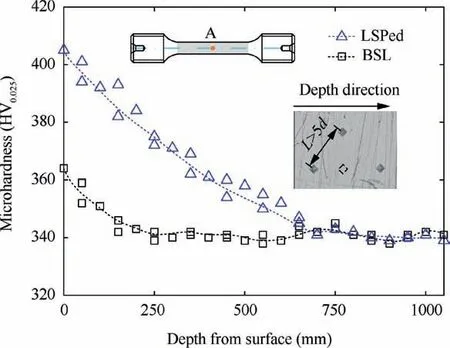
Fig.5 Microhardness before and after LSP at middle section position.
3.4.EBSD analysis of radial depth direction
Fig.6 shows EBSD maps of the specimens before and after LSP.Inverse pole figure(IPF)with a radial depth of 15μm from the surface,grain boundary misorientation and grain size in the middle section from the surface are studied.There is a severe plastic deformation layer contributing to refined grain at the depth of 15μm and a transition layerⅠof plastic deformation at the depth of 15-25μm in Fig.6a and b.However,it is difficult to observe grain refined except flat grains parallel to the surface in the transition layerⅡunder the depth of 25μm.It can be seen that grains before LSP(Fig.6(a))are coarser,and grain after LSP(Fig.6(b))are significantly refined where grain size of 1.57μm(Fig.6(e))after LSP is smaller than baseline’s grain size of 2.98μm(Fig.6(d)).During HCF process,dislocation motion is activated.Different dislocation movement modes,such as tangle,recombination,annihilation etc.,cause grain refinement.24Fig.6(c)shows IPF legend(red:[0 0 1],blue:[1 1 1],green:[1 0 1])for the selected area.In Fig.6a and b,grain colors have significant changes,which indicate obvious rotation behavior of grain orientation in the LSP process.For the baseline specimens,28.3% of grain boundaries with low misorientation angles(θ<15°,also considered as low angle grain boundaries)are confirmed in Fig.6(f),while,after LSP,31.1% of grain boundaries with low misorientation angles are observed in Fig.6(g).The increase of low misorientation angles indicates the presence of subgrains and the formation of new grain boundaries.
3.5.Tensile properties
Fig.7 shows the engineering stress-strain curves of the baseline and LSPed specimens manufactured by 32CrNi steel,Region I corresponds the elastic deformation stage of the material.RegionⅡcorresponds the plastic deformation stage of the material,and there is the corresponding view of the plastic deformation stage at high-magnification for the corresponding tensile specimens.Region III corresponds the necking stage of the material.The baseline and LSPed specimens yield within a small strain range,then enter the plastic deformation stage and end up at the necking stage.As shown in region I,when the engineering strain of all specimens is less than 0.5%,the relationships between engineering stress and engineering strain are similar,and the rake ratios of the linear region have no significant change for the baseline and LSPed specimens.It indicated that LSP has little effect on elastic deformation behavior of 32CrNi steel.
It is clear that the baseline specimens have a turning point as a yield point at plastic deformation stage compared with the LSPed specimens.However,deformation resistance of the LSPed specimens becomes flexible and yield deformation behavior becomes unconspicuous.It indicated that LSP affects plastic deformation behavior of 32CrNi steel and there is no obvious sign of yield phenomenon.From regionⅡ,we can see that ultimate tensile strengths almost have no change before and after LSP,and the literature25have also shown that the ductility of alloys and metallic materials usually are related to the ultimate tensile strength.As shown in region III,the LSPed specimens have smaller strains up to plastic instability point which decreases by 23.1%than that of the baseline specimens,indicating that the LSP reduces the elongation of 32CrNi steel.
Table 2 shows the tensile property of the specimens before and after LSP.It can be seen that the elongations of the baseline specimens are 15.5%,15.5% and 17.0% respectively,and that of the LSPed specimens are 14%,13.5% and 14% respectively.During the experiment,the generation of random errors can be seen intuitively from the elongations of specimens in the same group.Therefore,getting rid of the Baseline 3 specimen and the LSPed 2 specimen,the Baseline 1,2 specimens and the LSPed 1,3 specimens are more direct and practical.And the following is a comparative analysis of the baseline 2 specimen and the LSPed 3 specimen.It can be seen from Table 2 that the yield strengths of the Baseline 2 specimen and the LSPed 3 specimen are 1151 MPa and 1023 MPa respectively,which is reduced by 11.1%.The tensile strengths of specimens before and after LSP are 1190 MPa and1199 MPa respectively,which have no change.The elongations of the specimens before and after laser shock peening are 15.5% and14.0% respectively,which is reduced by 9.7%.The shrinkages before and after LSP all are 60%,indicating that the shrinkage has no change.Table 2 shows that the elongation of 32CrNi steel is reduced,indicating that plasticity of the material is reduced,but shrinkage has no change.The yield strength of 32CrNi steel by LSP is reduced,but tensile strength has no change.
3.6.Fracture mechanism
The tensile fractures of the Baseline 2 and LSPed 3 specimens were studied as shown in Fig.8.It is clear that fracture surfaces are characterized by pars fibrosa,radiation area and shear lip after and before LSP.The fracture source occurs in pars fibrosa and spreads through radiation area,and finally ends up in shear lip.As is shown in Fig.8(a)and(b),the pars fibrosa area of the LSPed 3 specimen is smaller than that of the Baseline 2 specimen,indicating that LSP reduces the plasticity of 32CrNi steel.The whole fracture area is also reduced because of the pits and 50% overlapping rate produced by the shock waves.It results in the area of shear lip reduced,but other total area of pars fiber and radiation area remains unchanged.
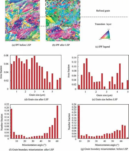
Fig.6 EBSD results before and after LSP at middle section position.
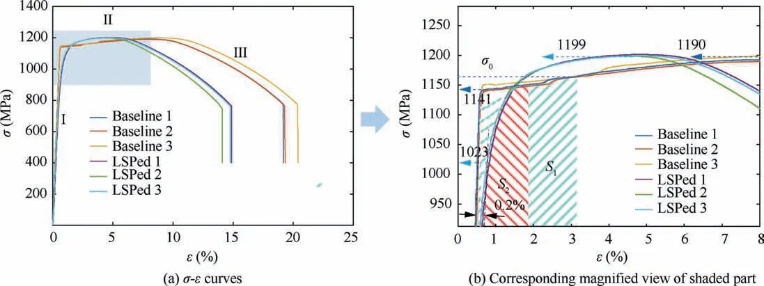
Fig.7 Tensile properties of baseline and LSPed specimens.

Table 2 Tensile property of 32CrNi steel.
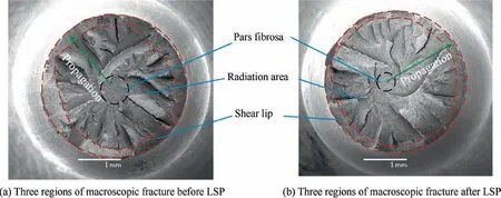
Fig.8 Morphology characteristic of tensile fracture.
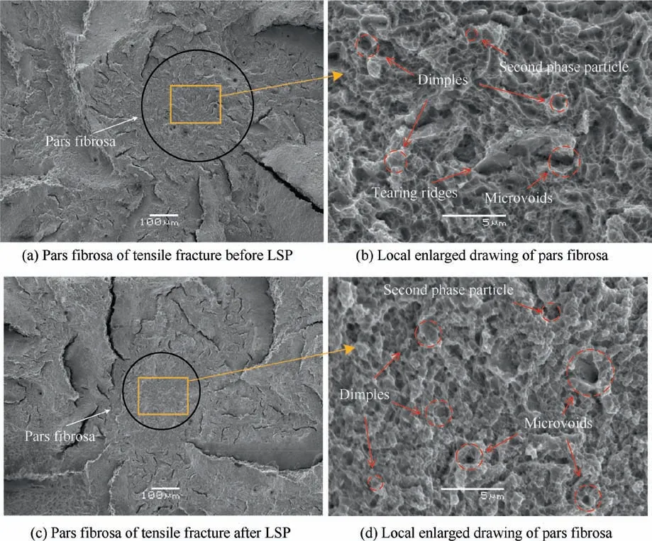
Fig.9 Crack initiation region of tensile fracture.
As is shown in Fig.9(a)and(c),the pars fibrosa area of the LSPed specimens is smaller than that of baseline specimens.Laser shock peening makes the difference value of residual stress between the surface and the axle center of tensile fracture increased,which leads to the unevenness of tensile fracture.Poor stability makes the pars fibrosa area decreased,and it results in the plasticity of the 32CrNi steel reduced.It can be seen from Fig.9(b)and(d)that there are many dimples with second phase particle and microvoid in fiber fibrosa before and after laser shock peening.And the dimple size of the LSPed specimens is bigger than that of baseline specimens,indicating the plasticity of the LSPed specimens is reduced.
Fig.10 shows the transition area between radiation area and shear lip of the Baseline 2 and LSPed 3 specimens.In the radiation area,there are many cleavage steps and cleavage surfaces.Moreover,the radiation area presents obvious tearing edges,and the transition area produces a great tearing force.There all are river patterns,bench patterns in shear lip,and tearing ridges in Fig.10(c)and(d).Cleavage steps come out clearly in radiation area.River pattern is divided into several small rivers from inside to out,and crack propagation direction of specimens can be observed more directly through river pattern,while the beach pattern appears below the transition line between radiation area and shear lip.And dimples are flatter in shear lip than that in pars fibrosa.We can see that dimples of the LSPed 3 specimen in shear lip are flatter than that of the Baseline 2 specimens,indicating that laser shock peening makes 32CrNi steel toughness lower.It is clear that there are more tearing ridges in radiation area of the LSPed 3 specimen than that of the Baseline 2 specimen.As is shown in inverse pole figure(IPF)at the same depth before tensile tests in Fig.10(e)and(f),grains of the baseline specimens are loosely distributed(upper left corner in Fig.10(e)).Shock waves induced by LSP make grains transform from loose grains into flat grains parallel to surface(upper left corner in Fig.10(f)).It slows down the process where flat grains generate transgranular fracture because of crack propagation direction perpendicular to flat grains.26However,the total tensile resistance changes little as shown in Table 2.
3.7.The influence of laser shock peening on mechanical property
As is shown in Fig.11,fracture first occurs in a crystal for the onset of plastic deformation.27A crystal is characterized in terms of the resolved shear stress,τR,acting on a specific slip plane along a specific slip direction.The load P can be resolved along b to give a shear force,the corresponding initial shear stress,τR0,resolved on the slip plane is the shear force,Pcosφ0,divided by the area of the slip plane,Acosλ0.Considering residual stressσresinduced by laser shock peening,so that

Due to the absence of an external moment after LSP,elastic stress at the core of the specimen must be balanced by residual compressive stresses26and the following equation also be satisfied

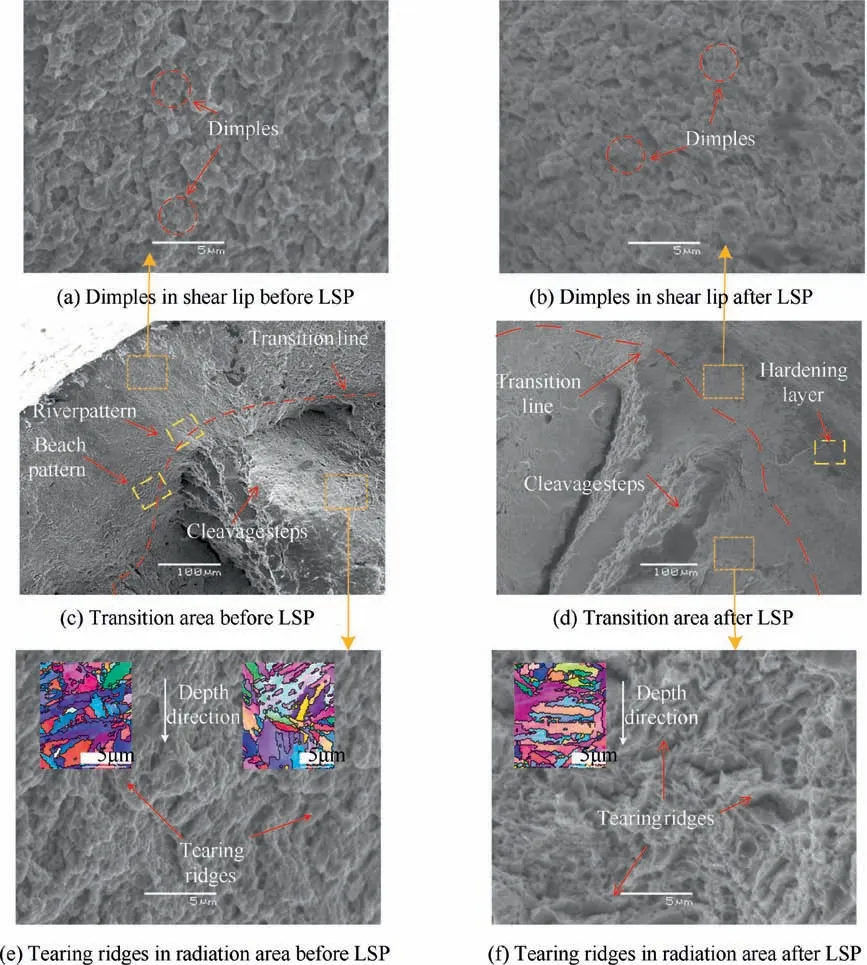
Fig.10 Transition area between radiation area and shear lip of tensile fracture.
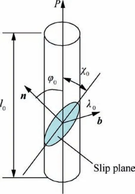
Fig.11 A schematic diagram of a crystal showing orientations of slip plane and slip direction.
From the equilibrium Eq.(2),greater and deeper compressive residual stress induced by LSP on the subsurface makes the core of the LSPed specimens produce more elastic tensile stress than that of the baseline specimens.The instantaneous shear stress of the inner crystal increases to the critical value τcfirst according to Eq.(1),and the plastic deformation of the whole LSPed specimen appears at less strain than that of the baseline specimens(as shown in region I of Fig.7).As a result,the material yields prematurely and yield characteristic transforms from obvious yield point to no yield phenomenon,which corresponds a smaller pars fiber area(Fig.9(a)and(c)).The literatures14,10,28also show no yield phenomenon of the materials after LSP;However,it is difficult for them to explain whether it is caused by LSP because there all are no yield characteristic before and after LSP.As the crystal deforms and the slip systems rotate with respect to the loading axial,the final crack propagation direction is parallel to the radial depth direction.Flat grains perpendicular to the radial depth(upper left corner in Fig.10(f))slows down crack propagation,and tearing edges transform from loose to slender feature.which is beneficial to improve the fatigue performance of 32CrNi steel.The literatures28-30reported tensile strength improvement of austenitic stainless steels by LSP,where higher density of dislocation structure greatly enhances the deformation resistance.This also is an affirmation on the impact of LSP in increasing the mechanical properties of titanium alloy,31brass alloy13and aluminum alloy.16,32However,for 32CrNi steel as lath martensite steels,shock waves induced by LSP also make a large number of flat grains transform from the irregular directions(upper right corner in Fig.10e)into the direction parallel to the surface(upper left corner in Fig.10(f)),which consumes a lot of laser energy instead of producing high density dislocations.As a result,a small amount of dislocation density can’t greatly enhance the tensile deformation resistance,and tensile strength induced by LSP changes little(as shown in region III of Fig.7).
Energy based fatigue methods33,34point out that the relationship between average plastic strain energy and number of cycles to failure has been presented as follows,

where Kpandαare measure of plastic strain energy coefficient and plastic strain energy exponent respectively.
The smaller plastic strain energy every cycle,the longer the total life.It is clear that the enclosed area of S2by stress-strain after laser shock peening is lower than that of the baseline specimens(S1)under the same fatigue stress load ofσ0.While yield occurs early and tensile property remains unchanged,the reduced area induced by LSP is beneficial for improving fatigue life from Eq.(3).LSP contributes to a certain depth of hardened layer on the surface,indicating that the plasticity of the surface layer decreases,fracture prematurely occurs and the shrinkage decreases(Fig.7(b)).On the one hand,laser shock peening causes large residual compressive stress on the surface and prevents crack propagation by reducing the equivalent external stress26;on the other hand,shock waves induced by laser shock peening makes the coarse grains appear flat on the subsurface,and slow down crack propagation by producing a greater tearing force by present obvious tearing edge in the transition region between radiation area and shear lip(Fig.10(f)).It is bigger compressive residual stresses and flat grains parallel to surface that slow down propagation of fracture source and make tearing edge transform from loose to slender feature,which is beneficial to improve the fatigue performance of 32CrNi steels.
The research shows that laser shock peening is a new surface modification technology,which can improve fatigue life by changing surface integrity.To have a basic understanding of evolution behavior between fracture behavior and surface integrity of 32CrNi steel and take into account the timeconsuming and laborious fatigue test,it is necessary to study the fracture mechanism of crack initiation and propagation induced by laser shock peening through tensile specimens.
4.Conclusion
In this study,tensile specimens on 32CrNi high strength low alloy steel were operated before and after LSP.Then surface integrity was analyzed,tension tests were carried out to obtain mechanical property and fracture information.Contrastive analysis is performed to achieve the following summary:
(1)Shock wave induced by laser shock peening causes large plastic deformation,the LSPed specimens have a rougher surface(Ra=1.263μm,Rz=9.303μm)due to pits and overlapping marks.As the increment of depth from the surface,the residual stress shows a scoop shape where residual stress on the surface is-314 MPa,depth is 0.903 mm,and compressive residual stress first reaches a maximum value of-441 MPa at the depth of 126μm.
(2)LSP contributes to a certain depth of hardened layer on the surface where there are microhardness of 405 HV0.025on the surface and the depth of 0.7 mm.Yield strength and elongation decreases by 11.1% and 9.7%respectively,but tensile strength has no change.As the same time,yield characteristic transforms from obvious yield point to no yield phenomenon and yield occurs earlier,where the reduced area induced by LSP is beneficial for improving fatigue life.
(3)The deeper compressive residual stress induced by LSP causes pars fibrosa area at the center of specimen decreases and have smaller dimples than that of the baseline specimens.And shock waves induced by laser shock peening makes the coarse grains appear flat on the subsurface,it prevents crack propagation by producing a greater tearing force with obvious tearing edge in the transition region between radiation area and shear lip.
Declaration of Competing Interest
The authors declare that they have no known competing financial interests or personal relationships that could have appeared to influence the work reported in this paper.
Acknowledgement
This study was co-supported by the National Natural Science Foundation of China(No.51375055).
 CHINESE JOURNAL OF AERONAUTICS2021年6期
- CHINESE JOURNAL OF AERONAUTICS的其它文章
- Performance evaluation of creep feed grinding ofγ-TiAl intermetallics with electroplated diamond wheels
- Thermomechanical coupling effect on characteristics of oxide film during ultrasonic vibration-assisted ELID grinding ZTA ceramics
- Modeling and experiment of grinding wheel axial profiles based on gear hobs
- Electrochemical machining on blisk channels with a variable feed rate mode
- Framework and development of data-driven physics based model with application in dimensional accuracy prediction in pocket milling
- Electrode design using revolving entity extraction for high-efficiency electric discharge machining of integral shrouded blisk
