Modeling and experiment of grinding wheel axial profiles based on gear hobs
Shuying YANG, Weifang CHEN
College of Mechanical and Electrical Engineering, Nanjing University of Aeronautics and Astronautics, Nanjing 210016,China
KEYWORDS
Abstract Hobbing is one of the crucial gear manufacturing processes with high precision and high efficiency.In order to improve the accuracy of hobbing and hob relief grinding,more precise grinding wheels are demanded for relief grinding in the production of gear hobs.In this paper,a new and accurate mathematical method for calculating the axial profile of grinding wheel based on the corresponding gear hob to be ground is proposed.Considering that most researches have been conducted to focus on the optimization of hob geometric feature and only can be applied to a specific type of hand of helix and rake angle of gear hobs.The method in this paper can be served as a general algorithm for generating axial profile of grinding wheels on the basis of the spatial envelope theory,the principle of coordinate system transformation,and studies on normal profile of single-tooth.The accuracy of grinding hobs is based on applying the approach in practical manufacturing.Taking two typical different kinds of pre-grinding gear hobs as examples for calculation and experiment,the results of tooth profile errors strengthen the position that the validity and feasibility of this method,it can be employed for gear hob design and grinding processing.
1.Introduction
Gear hob is one of the highly significant tools for machining spur or helical gears covered by a wide range of modulus.Commonly,gears with the same modulus,pressure angle but different number of teeth can be processed by using a hob with the same modules.1-3Due to the excellent adaptability and high efficiency,hobbing is currently the most widely used one in various machining methods of gears.Accurate gear hob is the guarantee of high-precision gear machining and at the same time,hob relief grinding is a key process for hob precision manufacturing.
With the increasing accuracy requirements of gears,various researchers have made efforts to improve the accuracy of the hobbing process.It is well recognized that the hob geometry can strongly affect the performance of cutting tool and the efficiency of gear hobbing work.4Most researches mainly focus on the optimization of hob geometric feature.Hsu and Su5described a mathematical model of the modified hob with variable tooth thickness,and made a contrast between the conventional hob and the mentioned modified hob in tooth profile topologies,contact method and transmission errors of the work gear pairs.Aiming at decreasing the regrinding error,Li et al.6conveyed an equal relief angle method by taking into account the relation between hob relief angle and tooth profile errors.Velex et al.7,8made related researches on hob modeling and optimization,a hob geometry parameter optimization method was proposed to reduce roll cutting error and improve hobbing accuracy.Klocke et al.9developed a continuous gear hobbing simulation to calculate the geometry of the hob and different characteristic values can also be given to the hobbing process,such as chip thickness and cutting amount to analyze the final workpiece tooth profile.Sun et al.10modeled the relationship between hobbing process and geometric deviation of gears through particle swarm optimization and back propagation algorithm to improve hob accuracy and reduce geometric errors.
Generally,the distortion phenomenon is inevitably at the stage of grinding lateral sides of hobs along radial direction and therefore,a large tooth profile error is generated.11-14Although optimizing the hob geometry has been widely applied to improve the accuracy of hobbing,it will greatly increase the difficulty of the hob design and decrease operating efficiency.Moreover,the distortion phenomenon in grinding process cannot be commendably controlled or eliminated.Thus,improving the accuracy of grinding wheel modification shape to achieve the high-precision of tooth profile left and right flank of gear hob attracts increasing interest.Taking into account the fact that grinding wheels have a substantial effect on hob tooth flank correction in the last machining operation,Tamura and Gunbara proposed algorithms of constructing models of forming grinding wheels,and the tooth contour deviation can be limited no more than 10μm in case of vertical regrinding angle of vertical outline hob is 16 degree.15The complexity of constructing mathematical model of tool curved surface is determined by mutually enveloping of the action surface between hobs and grinding wheels in the process of relief grinding.16-18The helical surface formed by enveloping is nonlinear,and as a result,tooth profile is in the form of curve for each section.Yoshino et al.19analyzed profile shape of grinding wheel and hob rake surface in the basis of space engagement.These studies considered geometry feature of grinding wheel action face,but they regarded the hob rake face as the calculation object to engage with the action face of grinding wheel is not suitable for space grinding motion.
The method is developed in this paper in respect to calculate the axial profile of the grinding wheel based upon solving the condition of surface enveloping and grinding geometry.Linear contact requires that action surface of a single hob should be spatially engaged with the grinding wheel axial profile in the machining process of shaping gear hob teeth with the application of hobbing technology.It is accepted that normal tooth profile of the hob is considered to be conjugate with the tooth profile of the workpiece,solution of normal tooth profile of the hob will become an essential basis for analyzing axial profile of relieving grinding wheels.In this paper,an accurate radical relief grinding model is established based on spatial motion relation of gear hob and grinding wheel.Different from the traditional one,the more standard normal tooth profile instead of the rake face of the hob is adopted as the calculation basis to achieve the axial profile generation of the grinding wheel.It will be more tally with the actual conditions and decrease tooth profile error caused by unreasonable grinding contact.In addition,the specific feature of the mathematical method is that it establishes a general computing model to solve numerous different grinding condition.Discussed are conditions of:cutting-tool angle,including zero or positive rake angle;hand of helix,including right-handed,lefthanded or annular buckle which is non-handed.Finally,clearly identify the validity of the developed method by using the numerical and experimental examples of the gear hob grinding.
2.Mathematical model of relief grinding
2.1.Coordinates establishment
In order to analyze the radical relief grinding movement of grinding wheels correspond to gear hobs,the model based on the spatial motion relationship of the above two objects in an arbitrary moment of the machining process is constructed in Fig.1.where SH(XH,YH,ZH)and SW(XW,YW,ZW)are respectively the moving coordinate systems fixed to the gear hob and grinding wheel.ZHand ZWare respectively the axes coincides with hob shaft and grinding wheel shaft.OHand OWare the axis midpoints of the gear hob and grinding wheel.
The key to calculating the grinding wheel axial profile is the analysis on relative location of two objects.As shown in Fig.2,the workpiece that needs to be ground is a right-handed gear hob and in Fig.3,it is an annular buckle gear hob.S X,Y,Z()in Figs.2 and 3 is a fixed spatial coordinate system;λis the angle between the gear hob and grinding wheel rotation axes,generally taking the helix angle on hob standard pitch circle and also regarding as the vertical installation angle of grinding wheel;θrepresents the relative turning motion parameter;A represents the distance between two rotation axes(ZHand ZW).
For the right-handed or left-handed hob,it performs a helical motion along its own axis,and the helical motion parameter P can be generally written with the following equation

where Pnis the hob normal pitch,shown as follows:


Fig.1 Radical relief grinding movement of a grinding wheel.
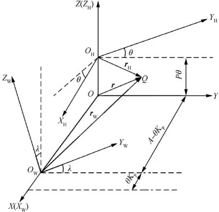
Fig.2 Relief grinding coordinate system of right-handed hob.
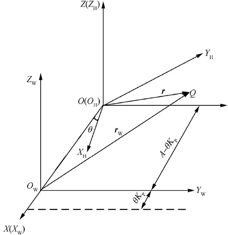
Fig.3 Relief grinding coordinate system of annular buckle hob.
where mnand n are respectively hob normal modules and thread number.
As for the annular buckle gear hob,the value of helix angle λis equal to zero,and accordingly,there is no helical motion in hob,neither the helical motion parameter P.
When the hob rotates per unit angle,radical movement distance of the grinding wheel along the gear hob can be gotten

where ZKis the number of chip-holding groove;K is the reliving quantity of gear hob.
2.2.Coordinates conversion
It is assumed that point Q shown in Fig.2 is an arbitrary engaging point between grinding wheel and gear hob in the grinding process.To achieve the transformation relation of point Q in coordinates,transition should be made from the gear hob coordinate system to the grinding wheel coordinate system.
In Fig.2,three reference coordinate systems are presented,supposing the unitary vectors of S(X,Y,Z)along the X,Y and Z axes are i,j and k,respectively.It can be assumed,as above,that the unitary vectors of SH(XH,YH,ZH)along the XH,YHand ZHaxes are iH,jHand kH,the unitary vectors of SW(XW,YW,ZW)along the XW,YWand ZWaxes are iW,jWand kW.The position vectors of the point Q relative to the origin of coordinates O,OHand OWare respectively r=[x,y,z]T,rH=[xH,yH,zH]Tand rW=[xW,yW,zW]T.
The transformation relation from coordinate system SH(XH,YH,ZH)to SW(XW,YW,ZW)can be described as the following equations

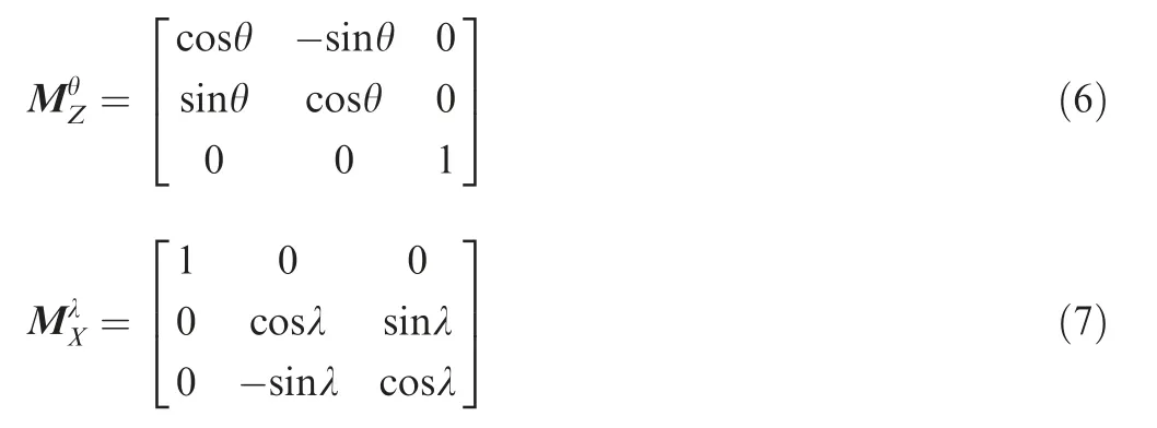
Then,coordinate values of the meshing points in SW (XW,YW,ZW)of Fig.2 can be determined with the equations below:

In the case where the grinding object of the grinding wheel is an annular buckle gear hob,shown in Fig.3,it is only necessary to set the value of P to zero,therefore,coordinate values of the meshing points can be reduced to the following form:

The key point of setting the value of P to zero also applies to the following conditions when it comes to annular buckle gear hob.The next calculations take the gear hobs with hand of helix as examples.
3.Axial profile of grinding wheel
3.1.Instantaneous meshing condition of relief grinding
In the coordinate system SH(XH,YH,ZH)of Fig.2,the shaping motion of gear hob is comprised of three parts.The first part is hob rotation,the second is translational motion of the hob along its axis(ZH)and the last is grinding wheel radical feeding movement.The grinding wheel rotation can be omitted since it is not related to the helicoid-formation.
Assuming that gear hob angular velocity isωH,the linear velocity of meshing point Q with the gear hob movement can be determined from the following equation:

and the following denotation on linear velocity of meshing point Q with grinding wheel movement is adopted

According to the Eqs.(10)and(11),the equation of relative velocity of meshing point Q can be obtained by

Considering the fact that meshing condition in space of the two curved surfaces must be tangent at the meshing point Q,and the relative velocity should be on the common tangential plane,hence,there must be common normal vector in the meshing point between the envelope surface of grinding wheel and hob grinding surface,and it is perpendicular to the relative velocityνHW.The positional relationship can be expressed as follows:

where nHis the normal vector of the gear hob grinding surface at the meshing point.
The tangent vectorτHof point Q corresponds to the hob cutting edge is also perpendicular to nH,andτHis equal to the first-order derivation of rH.The positional relationship shown in Fig.4 is represented as

On the basis of above results,normal vector is perpendicular to relative velocityνHWand tangent vectorτH,one can conclude that nHconverts to the fixed coordinate system S X,Y,Z()is

whereτFis transition ofτHfrom coordinate system SH(XH,YH,ZH)to S(X,Y,Z),the relationship can be obtained as
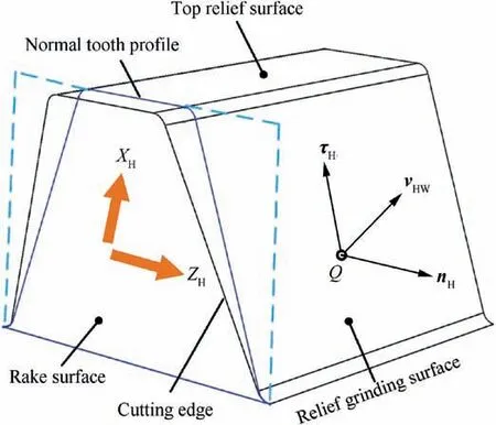
Fig.4 Schematic of a hob tooth positional relationship at the meshing point.

Given the envelope conditions,kW,rWand nHare coplanar,it can be generally written as follows:

where nWis transition of nHfrom coordinate systemSH(XH,YH,ZH)to SW(XW,YW,ZW),it can be given by equation

Substituting Eqs.(8)and(16)into Eq.(18),we can get the instantaneous meshing condition of relief grinding
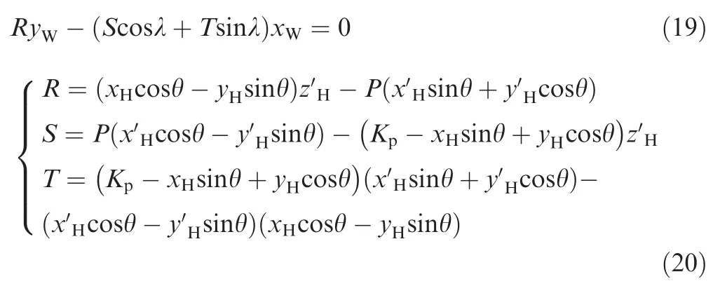
where R,S and T are intermediate variables.
Substituting the coordinate value of the meshing point Q in coordinate system SH(XH,YH,ZH)into Eq.(19),the relative rotational motion angleθof the gear hob and the grinding wheel at any time is determined.Then we can get the point reliving grinding contact point G corresponding to the point Q on the rotating surface of the grinding wheel.The meshing curve is the ensemble of instantaneous meshing points on the envelop surface.
3.2.Calculation of grinding wheel axial profile
After the coordinate values of meshing points are obtained,we can get the axial profile of grinding wheel by turning the meshing points around the axis of grinding wheel and the y coordinate of the meshing point is equal to zero in axial profile plane XWOWZWof grinding wheel.It can be denoted with the equation below:

4.Normal tooth profile of gear hob
The grinding accuracy of grinding wheel is determined regarding its axial profile based on the value of meshing points and the relief grinding surface of the hob is the envelope surface of the grinding wheel axial profile during the grinding process.In order to reduce the tooth profile error caused by the difference between the rake angle and the chip-holding groove shape,we use the standard hob normal profile of tooth as the calculation object.Fig.4 shows the position of normal profile in gear hob tooth.
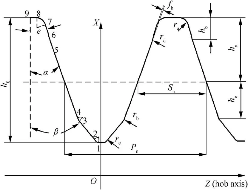
Fig.5 Normal tooth profile of a hob before grinding.
Since the involute gear hob is difficult to manufacture and detection,it is often replaced by an Archimedes gear hob or a straight sided normal gear hob that the tooth profile of the axial profile and the normal profile are composed of straight lines and transition arcs,it can simplify our calculations.Compared with Archimedes gear hob,the straight sided normal gear hob has a large tooth profile error,so the former one gets a wider range of applications in production.The examples used in this paper are also the Archimedes gear hobs.The relief grinding surface of the gear hob is designed by Archimedes curve.Even if the rake face of the hob is reground,the cutting performance of the new hob is the same as before under the condition of without changing the tooth profile.20The complicated normal tooth profile of an Archimedes gear hob before grinding is shown in Fig.5 and normal tooth profile coordinate system is constructed.The profile on the right side of the symmetry axis is mainly calculated.
The parameters of hobs are given in Table 1.Value A represents the parameters of a right-handed gear hob with straight chip-holding groove shape and zero-degree rake angle,value B represents the parameters of an annular buckle gear hob with straight chip-holding groove shape and positive degree rake angle.Both of the above two are regrinding gear hobs with single thread.
In order to simplify the calculation and facilitate the measurement,each segment of normal tooth profile of the gear hob can be expressed as a straight line or an arc.As shown in Fig.5,1-2 segment represents the tooth bottom arc,2-3 segment is the chamfer part,3-4 segment is the arc transition arc between chamfer and major cutting edge,4-5 segment is the major cutting edge,5-6 segment represents dedendum transition cutting edge,6-7 segment represents the feeler part,7-8 segment is the addendum arc and 8-9 segment is the straight line of top edge.
The equation of tooth bottom arc is written by
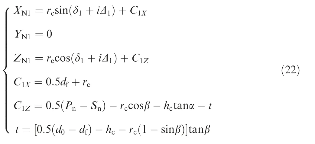
where C1X,C1Zare X and Z coordinates of tooth bottom arc center,respectively;Δ1is the iterative value fromδ1toδ2;i is iteration number;δ1andδ2represent the tooth bottom arc starting and end angles which are equal to 1.5πand 2π-β;t is intermediate variable.
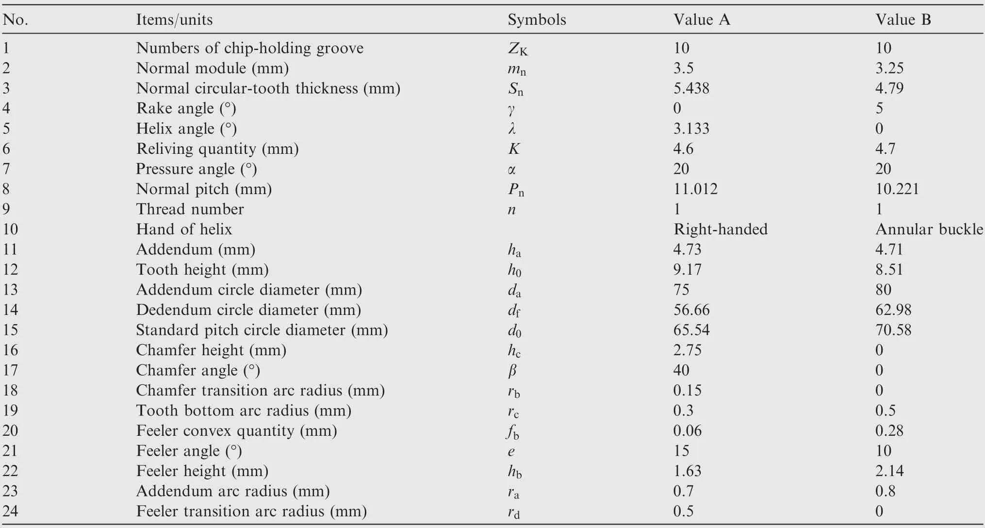
Table 1 Parameters of gear hob.
The straight line of chamfer part can be determined by

whereΔ2is the iterative value from the Xcoordinate of chamfer starting point L1to end point L2.
The transition arc located between chamfer and major cutting edge,which is similar to the algorithm of tooth bottom arc as above.It can be described below

whereΔ3is iterative value of chamfer transition arc angle which ranges from 2π-β()to 2π-α();C2X,C2Zrepresent X and Z coordinates of chamfer transition arc center,respectively.
The denotation of straight line of major cutting edge is adopted by the following equations

whereΔ4is iterative value from the X coordinate of major cutting edge starting point L3to end point L4.The transition arc located between major cutting edge and addendum transition cutting edge is attained by
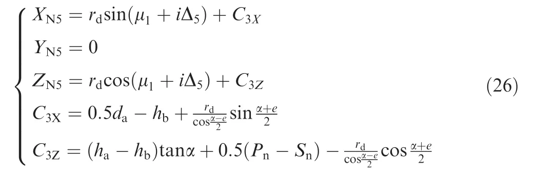
whereΔ5is iterative value of feeler transition arc angle,ranging from 2π-α()to 2π-e();C3X,C3Zare X and Z coordinates of feeler transition arc center,respectively.
The straight line of dedendum cutting edge is defined as
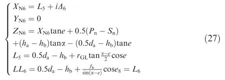
whereΔ6is iterative value from the X coordinate of dedendum transition cutting edge starting point L5to end point L6.
The straight line of feeler can be denoted to the following form

whereΔ7is iterative value that ranges from the X coordinate of feeler starting point L7to end point L8.
The addendum arc is equal to

whereΔ8is the iterative value of addendum arc angle,ranging fromπ-α()to 0.5π;C4X,C4ZrepresentX and Z coordinates of addendum arc center,respectively.
The straight line equation of top edge is expressed as follows

whereΔ9is the iterative value that ranges fromxcoordinate of top edge starting point L9to end point L10.
5.Verification of the relief grinding method
5.1.Numerical examples and discussion
Substituting the parameter data in Table 1 into the curve equations of the gear hob normal tooth profile and simultaneously dividing each segment curve into 5 points based on the Newton method,two grinding axial profile point coordinates can be obtained.The spatial axial profile of two grinding wheels are plotted as shown in Fig.6 in the discrete form of a set of points by applying to the algorithm above.After fitting these discrete points,we can get the accurate axial profile in XWOWZWplane of two grinding wheels in Fig.7.For the convenience of comparing the proposed method with traditional method,the coordinate difference values of two grinding wheel axial profiles based on two methods are given in Fig.8.The results reveal that the coordinate Xwof grinding wheel axial profiles show little significantly different.However,an apparent difference is noticed in the coordinate Zw.
5.2.Experiment of relief grinding

Fig.6 Spatial axial profile points of two grinding wheel.
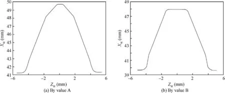
Fig.7 Axial profiles in XWOWZW plane of two grinding wheels.
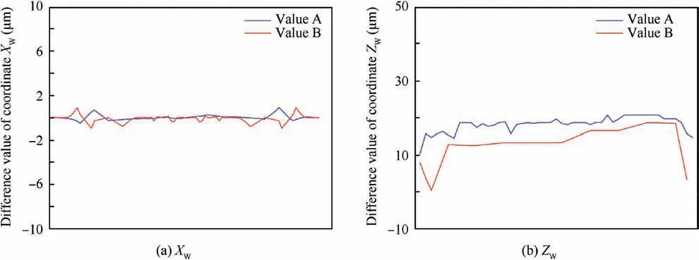
Fig.8 Coordinate difference value between proposed method and traditional method.
We conducted a relief grinding experiment with the two sets of hob parameters in Table 1 for further verify the accuracy of the mathematical method.Grinding wheel specifications and grinding parameters are listed in Table 2.Fig.9 shows the actual relief grinding process including grinding wheel dressing and gear hob relief grinding.In the whole movement process of the relief grinding,it is vital to use the diamond dressing wheel to trim the grinding wheel firstly so that the axial profile of the grinding wheel satisfies the space engagement with the gear hob.The software to calculate grinding wheel profile and control the movement of the dressing device is developed to implement the experiment.Through the axial and radical movement of the diamond dressing wheel and the rotational movement of the grinding wheel around its own axis to complete the trimming of the working face of the grinding wheel.The gear hob is then ground by the radial and rotational movement of the well-trimmed grinding wheel and the helical motion of the hob.This experiment uses the parallel trimming method of the diamond dressing wheel that reciprocates to trim grinding wheel in sequence of 1 to 7 as shown in Fig.10.
The tooth profile errorFfsof gear hob is the deviation of the actual position of a point on the cutting edge from the specified position on the envelope thread and the deviation value is defined in a measurement surface which is perpendicular to the profile of the tooth profile.The tooth profile error on the left and right flanks of the cutting edge of one hob tooth after grinding is measured on the JINGDA JE20 gear measuring center is shown in Fig.11.The measurement position is along the tooth profile which is divided 20 measurement points evenly from root to top.For hobs with a rake angle of zero degree,the tooth profile to be measured is parallel to the cutting edge.And for a positive rake hob,the measured position is inclined by the positive degree from the rake face of the cutting edge.The measurement results are given in Fig.12.The parameters of hob A and hob B correspond to value A and value B in Table 1.Hob A is a right-handed gear hob with straight chip-holding groove shape and zero-degree rake angle,hob B is an annular buckle gear hob with straight chip-holding groove shape and positive degree rake angle.In Fig.12,the horizontal axis represents the radius of the hob from root to tip and the vertical axis represents tooth profile error Ffs.The actual tooth profile errors for both flanks of hob A and hob B are 4.7μm,11μm,10.5μm and 9.8μm,respectively.The measurements showed that the value of tooth profile errors of two hobs are within a small gap compared with nominal value.According to the hob tolerance regulation DIN 3968,the two hobs used for experiment can reach at least class A under the condition of only considering the tooth profile error,and the tooth profile left flank of hob A can even reach class AAA.As a comparison with the measurement results inFig.13 which is obtained by previous algorithm that mainly take the rake face of the hob as the calculation basis to achieve the axial profile generation of the grinding wheel,we get the tooth profile errors for both flanks of hob A and hob B in Fig.13 are 16.4μm,15.7μm,22.2μm and 21.8μm,respectively.It can be obviously seen that for the same hob,the tooth profile errors in Fig.10 are much less than those in Fig.13.As expected,the experiments of relief grinding demonstrate that in case of actual processing,the application of this method make the accuracy of hob tooth profile can better satisfy production requirements.

Table 2 Grinding wheel specifications and grinding parameters.
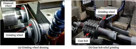
Fig.9 Relief grinding experiment.
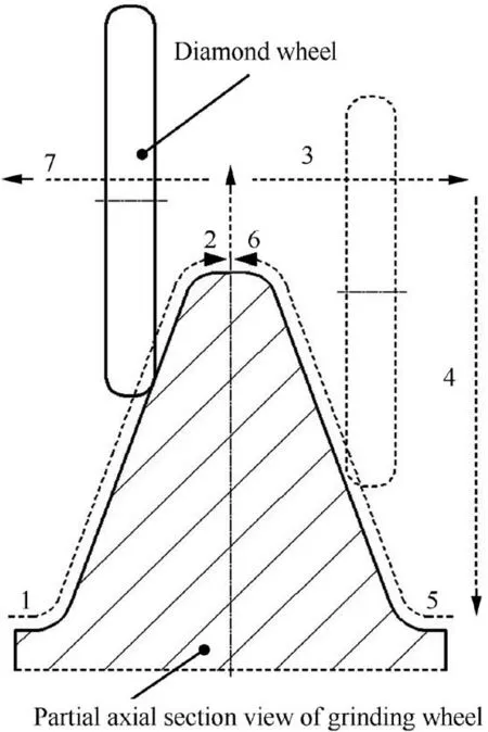
Fig.10 Parallel trimming of diamond wheel.
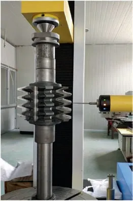
Fig.11 Measurement of hob tooth profile error.
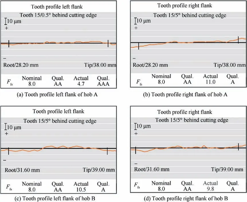
Fig.12 Measurement results of tooth profile error.
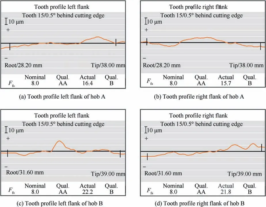
Fig.13 Measurement results of tooth profile error of traditional algorithm.
6.Conclusions
The relief grinding process plays an extremely important role in the production of gear hob and the grinding accuracy will have a direct and profound influence on the hobbing accuracy.To further improve hobbing accuracy,more precise grinding wheel is urgently demanded and a new mathematical method for calculating the axial profile of grinding wheel is proposed in this paper.The crucial points and contributions of this paper can be briefly summarized as follows.
(1)The mathematical model is on the basis of principle of spatial engagement and matrix of rotational transformation.Various axial profile of grinding wheels can be generated with the help of this mathematical model and compared with traditional algorithms,it can be applied to relief grinding of gear hobs with different hand of helix or cutting-tool angle.
(2)An important question with regard to tooth profile error of gears is tooth mesh between gears and hobs,and therefore,improving the accuracy of the lateral sides of hobs is critical for gear processing.The standardized normal tooth profile instead of rake face of gear hob is used as a specific conjugate surface that meshes with the grinding wheel,it can be much easier to obtain the precise axial profile of grinding wheel.Equivalent the normal tooth profile of the Archimedes gear hob to the straight lines and transition arcs can greatly simplify the manufacturing and inspection cost of the gear hob.
(3)The relief grinding experiment with the two sets of hobs is carried out and the hob tooth profile errors for both flanks are within the accuracy range.The actual measurement results verify that this method can effectively improve the accuracy of hob tooth profile.It sheds new light on improving the production process of hobs and gears.
Declaration of Competing Interest
The authors declare that they have no known competing financial interests or personal relationships that could have appeared to influence the work reported in this paper.
Acknowledgement
All the authors of this article gratefully acknowledge the help and support of National Key Research and Development Project of China(2018YFB2001500).
 CHINESE JOURNAL OF AERONAUTICS2021年6期
- CHINESE JOURNAL OF AERONAUTICS的其它文章
- Performance evaluation of creep feed grinding ofγ-TiAl intermetallics with electroplated diamond wheels
- Thermomechanical coupling effect on characteristics of oxide film during ultrasonic vibration-assisted ELID grinding ZTA ceramics
- Electrochemical machining on blisk channels with a variable feed rate mode
- Framework and development of data-driven physics based model with application in dimensional accuracy prediction in pocket milling
- Electrode design using revolving entity extraction for high-efficiency electric discharge machining of integral shrouded blisk
- Performance analysis and application on Ti-6Al-4V of micro-forging system
