Electrode design using revolving entity extraction for high-efficiency electric discharge machining of integral shrouded blisk
Yucho JIA,Gunxin CHI,Yng SHEN,Kun ZHANG,Zhenlong WANG,*,Yukui WANG
a School of Mechatronics Engineering,Harbin Institute of Technology,Harbin 150001,China
b Capital Aerospace Machinery Company,China Academy of Launch Vehicle Technology,Beijing 100076,China
KEYWORDS
Abstract The integral shrouded blisk provides better performance with minimum weight,but its semi-open structure presents problems for its production.Manufacturing processes of these components require a removal of about 70%-90%of material from their blanks.Multi-axis electrical discharge machining(EDM)is commonly used for these processes,but its poor efficiency cannot meet the requirements of mass production.Strong flushing assisted high-current discharge is able to improve the machining efficiency.In this paper,this method was applied to manufacture the integral shrouded blisk.An electrode design method was proposed.Taking the largest revolving entity inside the flow channel as the base geometry,this laminated arc-shaped hollow electrode meets the requirements such as high pressure flushing,tool wear compensation,and easy to be made.A 4-axis linkage machining tool path with planetary motion was proposed.Taking an integral guide vane ring as an example,it has been experimentally verified that the time consumption for each channel using this method was reduced to a half of the ordinary EDM method,while the finished surface quality remains same.
1.Introduction
Turbomachinery plays an irreplaceable role in today’s energy,aerospace and transportation industry.Its high efficiency and complex structure make it a representative of today’s cutting-edge industrial technology.For example,aero engines and rocket engines not only require materials that are able to withstand the high temperature and high-pressure conditions,but also to be light-weighted and durable.Therefore,Nibased superalloys and titanium alloys are often used for the guide vane rings and turbine blisks of high-performance engines,and adopting an integrated design and adding blade shrouds.1This poses difficulties to its manufacture.In current manufacturing processes,up to 70%-90% of the material is removed from the blank for these parts.The narrow space surrounded by blades and shroud makes it difficult to adopt cutting methods.Non-traditional machining such as electrical discharge machining(EDM)and electro-chemical machining(ECM)has to be used,so the machining efficiency is low and the production cost is expensive.2-4In general,the compressor and turbine of an engine usually include multiple stages of blisks,and each stage contains dozens of channels surrounded by blades.Therefore,the machining efficiency of blisk is usually the bottleneck restricting the overall engine production capacity.5
In order to improve machining efficiency and reduce the overall manufacturing cost of blisks,it is necessary to increase the production efficiency for each step and shorten the process chain as much as possible.One way is adopting precision casting or forging methods to make a near-net-shape blank,which effectively reduces the burden on subsequent processes.With the development of additive manufacturing technology in recent years,it is now possible to directly use metal powder to sinter the blade disc blank,and combine other process methods to complete the blade surface finishing.6,7The representative of this idea is the LASERTECH 3D Hybrid series machining center designed by DMG.Combined milling and selective laser melting(SLM)in single platform,this five-axis machine tool is competent for some complex integral parts’production.However,the point-by-point scanning additive manufacturing is currently more suitable for special hollow structures with complex internal grids.Compared with rough machining from the blank,the efficiency of making near-netshape blanks in this way has not yet reached an absolute advantage.And because of the higher environmental requirements of metal additive manufacturing,the equipment is difficult to be integrated with EDM or ECM.Attempts using additive manufacturing and EDM(or ECM)still require multiple platform,and the process is troublesome.
Another way is to improve the efficiency of roughing and finishing as much as possible,and integrate all these processes on less platforms.Practice of this concept is machining center designed with both roughing and finishing capabilities.For example,some advanced ECM machine tools are able to achieve high-efficiency roughing and high-quality finishing by adjusting the power supply and auxiliary functions.8,9However,because these platforms are expensive,and the cathode design and manufacture require a series of analysis and optimization,EDM is still essential choice in production.10,11
The main difficulty of using EDM for integral turbine blisk is the electrode geometry designing and the tool path planning.Initially,these were achieved through a combination of channel entity scaling and inverse extraction trajectory searching.12The algorithm continuously calculates the electrode position in each step according to the preset electrode extraction direction and enabled axis,performs interference checks,and shrunk the electrode when it is impossible to avoid interference.This idea is still used today,and is characterized by a strict correspondence between electrode geometry and machining trajectory.13Later,this method has been gradually updated.Problems such as discontinuous trajectories,low path efficiency,and unusable electrodes were solved.Liu et al.14,15proposed a method that uses the electrode centerline and the channel centerline to guarantee that the electrode is always at the center during feeding.In this way,the trajectory’s continuity can be guaranteed,and a larger electrode entity can be obtained.Ayesta et al.16proposed an objective function and implemented a hybrid optimization method(Genetic Algorithm+Trust Region Reflective method),offering a generic tool path planning method that guarantees the smoothness of the erosion path,independently of the workpiece geometry and‘‘userdependent”features.Kang et al.17proposed the concepts of maximum free travel distance and local reference direction to optimize the machining trajectory of an integral centrifugal impeller.Perturbation movement was adopted to improve the process efficiency.18The feed rate control of EDM has been improved by Xi et al.in order to solve the problem of feed fluctuation caused by the difference between the feed rate control for rotary and linear displacement in the existing numerical control interpolation algorithm.The screw theory was introduced to analyze the forward kinematics of the multi-axis EDM machine tool,and the transformation matrix from the tool frame to the workpiece frame is derived.19In addition,an extended unit arc length increment interpolation for generalized NURBS curves was proposed.20After these improvements,the five-axis EDM machining process is more stable,and the overall machining time is shortened by 20-40%.
Through the application of aforementioned methods,almost all kinds of integral blisks can be machined by EDM now.Efficiency and cost have become the main factors restricting its practicality at present.EDM gradually removes material by superimposing pits formed by continuous pulsed discharges.There are two ways to increase its efficiency.First,it is necessary to optimize the stability of the machining process,avoid abnormal conditions,and increase the number of effective discharge pulses per unit time.Second,it is also worth trying to increase the material removed by each discharge without damaging the electrode and the workpiece.In recent years,the high-pressure flushing assisted large-current EDM roughing method is gradually gaining popularity.This method is characterized by the use of water based dielectric medium and high-pressure flushing to assist hundreds of amps of pulse discharge to achieve high-efficiency material removal.They were found to have good capability in the field of superalloy and titanium alloy rough machining.21,22By optimizing the electrode structure,a powerful flushing of several megapascals was applied to take the high-current discharge-melted materials away from the workpiece in time.This method significantly improves the machining efficiency of high-temperature alloys,titanium alloys.23,24GE developed Blue Arc and designed a special equipment for blisk production.25The efficiency of Inconel718 alloy is three times faster than milling,and the processing cost is reduced by 30%.Wang et al.26applied this method to integral blisk machining.A simplified laminated electrode was designed.Using non-rotating electrode,it was experimentally verified at a peak current of 200A.The results show that although the machining efficiency was improved,the finished surface was poor and the electrode consumption rate was pretty high.Not only should the machining allowance be reasonably arranged,but the tool wear compensation also requires more consideration in the electrode design and toolpath planning.
In order to promote the application of high-efficiency discharge machining in blisk production,an experimental platform for blisk processing was developed in this paper.An electrode design method based on largest revolving entity extraction was proposed.The proposed arc-shaped electrode makes it easier for tool path planning.The main content of this paper consists of 3 parts.Section 2 of this paper discusses the implementation of high-efficiency electrical discharge machining of integral shrouded blisks and its requirements for electrodes.The design method and tool path planning of the proposed largest revolving entity electrode are introduced in Section 3.In Section 4,a shrouded vane ring was taken as an example to verify the feasibility of proposed method.By reasonably determining the machining allowance,the blade surface quality obtained after finishing remains same compared with ordinary EDM.Finally,the conclusions are summarized in Section 5.
2.High-efficiency electrical discharge machining of integral shrouded blisk
The typical structure of an integral shrouded blisk consists of a hub,multiple blades and a blade shroud.As shown in Fig.1,the channel surrounded by the hub,blades and shroud has four curved surfaces.During the EDM process,the electrode needs to penetrate the entire disk first to remove the most material in the channel,and then accurately copy the four surfaces of the channel by copying movement.The surface formed during the penetration will be processed again in the copying process.The copying efficiency is strictly limited by discharge energy because it needs to complete fine surface finish.Therefore,improving the efficiency of penetration under the premise of ensuring the final surface quality is the key to increasing the overall efficiency.
2.1.High-efficiency electrical discharge machining of integral shrouded blisk channel
Different from the ordinary EDM,strong flushing assisted high-current discharge melts more material in each pulse.The molten pool formed by hundreds of amps discharge pulse is much larger and deeper.The molten material needs to be taken out of the molten pool in time by the strong flushing,otherwise it would resolidify and form a recast layer.This is the reason why it is difficult to remove materials by electrical arcing alone.The application of high-pressure flushing liquid would bring much more low-temperature dielectric medium comes into contact with the molten pool,and boiling phenomenon within the molten pool is enhanced.The molten materials in the molten pool rolls more violently,and more material would be driven out by the high-pressure flushing,resulting in a more efficient material removal.27Therefore,realization of high-efficiency material removal process requires three factors:suitable inter-electrode gap,strong fluid flushing,and sufficient discharge energy density.
In this paper,a compound machining platform was designed for the integral shrouded blisk machining.As shown in Fig.2,a high-pressure flushing circulation system was designed and integrated into a five-axis EDM machine tool.The dielectric is supplied to the hollow electrode through a plunger pump.The working pressure range is 0.8-4.5 MPa.A high current pulse power supply with continuously adjustable peak current 100-600 A was equipped.In software,the servo logic of high-efficiency discharge roughing mode was added to the original CNC system.In this mode,the feed rate of the tool electrode is determined and adjusted according to the average gap voltage,which is different from ordinary EDM.In addition,in order to protect the workpiece from burns caused by large current short-circuits,the electrode servo always detect the short circuit as first priority.Whenever a short circuit occurs,the electrode will stop feeding in time and retreat along the identical trajectory for a short period.It provides better circulation conditions between the workpiece and tool,thereby eliminating the transient short circuit caused by debris and avoiding the risk of severe damage.
The modified machining platform keeps all the functions of original EDM machine,while being compatible with highcurrent machining mode.The raw disk is fixed to the A-axis table and the electrode is installed at the end of the C-axis during the machining.Each channel was firstly rough machined using high-current machining mode,which removes almost 60-85% material within the channel.Then,the original EDM mode was applied to complete the blade surface finishing.
2.2.Requirements for electrode used in roughing
The high-efficiency discharge rough machining puts forward new functional requirements for the electrode.First,when applying a more powerful flush between the workpiece and the electrode,the electrode requires a well-designed internal channel to provide sufficient dielectric fluid flow.Second,while achieving high material removal rate(MRR),the actual tool wear rate is not neglectable.The geometry changes of the electrode caused by tool wear is fast.Therefore,a simple geometry that is beneficial to wear compensation should be adopted in the electrode design to increase the service life of each electrode and reduce the number of electrode replacements during machining.In summary,the demand for electrodes in this mode is summarized into three.
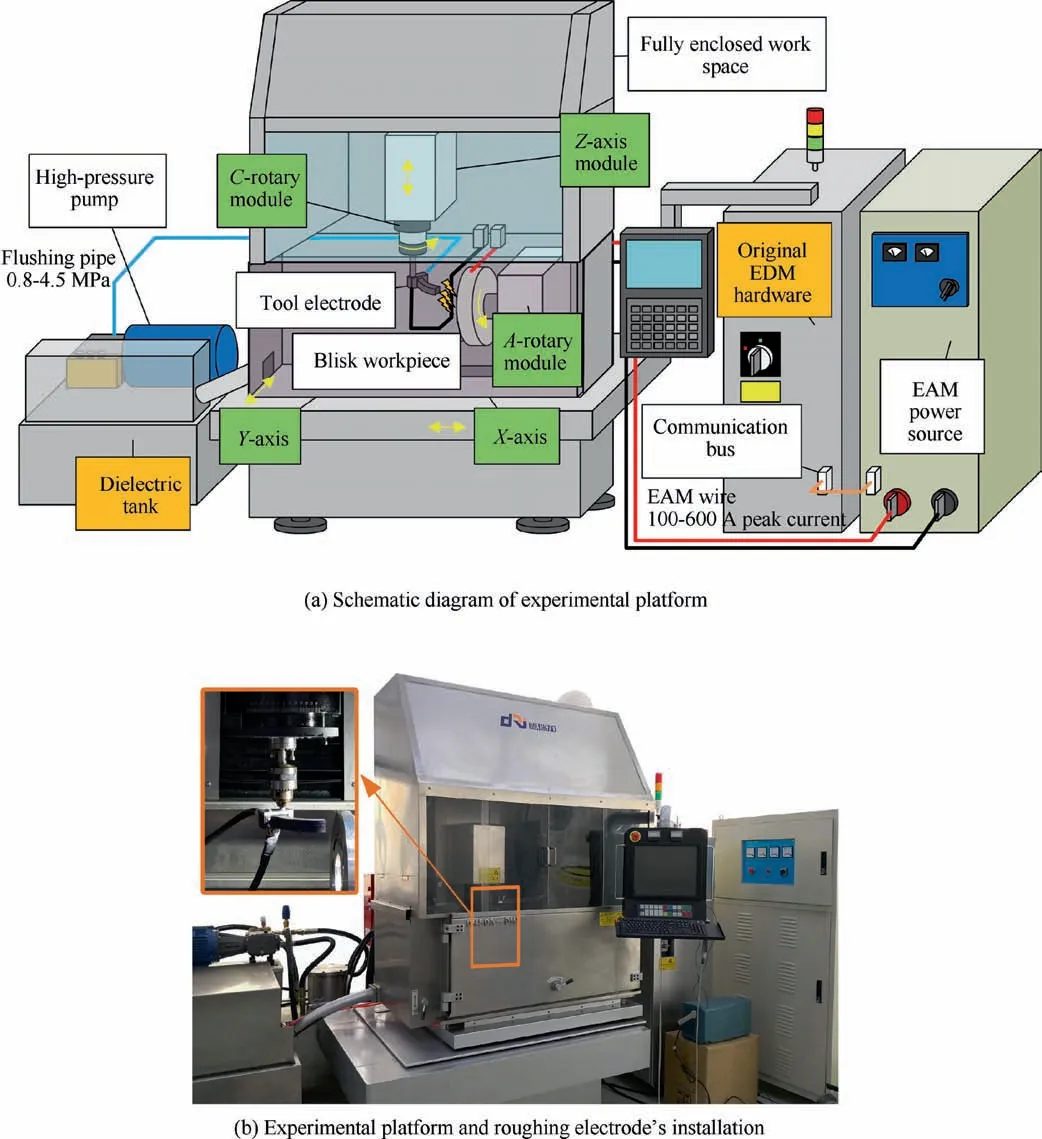
Fig.2 Schematic diagram of experimental equipment for strong flushing assisted high current electrical discharge machining.
1)The electrode needs to provide internal flushing channel,and easy to be made.
2)The electrode shape should be simple,and be beneficial to the compensation of high wear rate.
3)The electrode material selection needs to be cheap enough while meeting the above conditions to reduce cost as much as possible.
In addition,although the surface quality is not mandatory required in the roughing step,it is necessary to remove as much material as possible with sufficient safety allowance.Regarding this,the roughing electrode does not need to be equidistant and scaled according to the blade surface,but its geometry still requires reasonably design so as to fully exert the value of high-efficiency rough machining.
3.Electrode design method
Considering these requirements,a hollow,equal-section,arcshaped electrode is proposed to complete the channel penetration(i.e.roughing).This design makes it’s easier to compensate the geometry change caused by tool wear since the sections’shapes are identical,and also extend the service life of each electrode by extend the entity along the arc.For this reason,a method for extracting the largest revolving entity in the blisk channel geometry is proposed.The revolving entity obtained using this method is the proposed electrode’s base geometry.After reducing size,designing the internal flushing channel,entity division and other operations,the electrode that meets the processing requirements can be obtained.
3.1.Extraction of largest revolving entity within the blisk channel
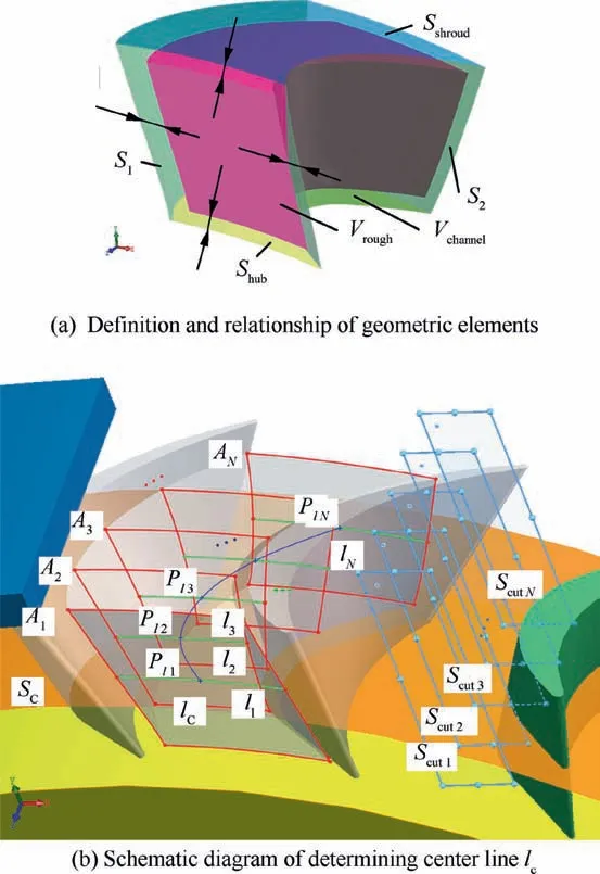
Fig.3 Geometric operation steps to find the centerline of channel lc.
Without loss of generality,a typical integral shrouded blisk’s channel geometry Vchannelis shown in Fig.3.The four surfaces of the channel are named S1,S2,Shub,and Sshroud.These four surfaces are equidistantly moved with scaling sizeδdetermined according to the preset rough machining allowance,and the new geometry formed is named roughing removal entity,Vrough.
The following step is to determine the largest revolving Vmentity within Vrough.In common CAD software,the complete definition of a revolving entity requires the determination of its revolving axis and its section profile.For a given entity Vrough,which could be regarded as a swept entity by a series of cross sections,the reasonable axis direction should be perpendicular to its bending direction.Therefore,it is necessary to determine a center line lcthat describes the flow channel’s bending tendency.By creating equidistant sections Scut1-ScutNof the channel along the disk’s axis,it’s easy to find that the section contours A1-ANof the section continuously changes,and the connection of each contour reflects the bending tendency of the channel.Along the disk’s radius direction,determine the hub radius r and flow channel height h,and create a cylinder surface Scwith radius:r+0.5×h.Then determine the intersection line l1-lNof the circle Rnwith A1-AN.Find the midpoints Pl1-PlNof these intersections,and connect them with Non-Uniform Rational B-Splines(NURBS)curves in sequence,the centerline of the flow channel lc.

Fig.4 Approximation of the channel centerline(Cx)and the revolving axis Ax.
Next,create arc Cxas an approximation the centerline lcto determine the revolving entity to be found.Define points Px1,Px2,and Pxon l1,lnand lcrespectively.As shown in Fig.4,the distance between Px1and Pl1,Px2and Plnalong the X direction(shown with red arrow in bottom left of Fig.4)is d1and d2.And dxrepresents the distance between Pxand Pl1along Z direction(shown with blue arrow).Thus,an arc Cxthrough points Px1,Px2and Pxis defined with a certain combination of d1,d2and dx.Assuming that Cxhas been determined,take points PC1,PC2,PC3,...,PCNfrom the Cxat equal arc lengths.Define the datum axis Axwith the center of Cxand perpendicular to the plane where Cxis in.Then define a new group of cut planes{Sxcuti}i=1,2,3,...,Nthrough the axis Axand points PC1,PC2,PC3,...,PCN,and redivide Vroughthrough these planes.A series of cross-sectional contours were got and shown with blue lines in Fig.5.Since the largest revolving entity Vmxwithin Vroughwith Axas its rotation axis must not exceed Vroughin each cross-section,the cross-section contours were used to generate the revolving entities{Vrevi}i=1,2,3,...,nseparately,and then the Vmxwas obtained by their intersection result:

During this process,the Cxwas determined by three variables d1,d2and dx,so the obtained entity is named Vmx.Thus,Vmis maximum result when adjusting d1,d2and dx:

The task of searching Vmwas achieved by an iteration program.Since the feasible range of d1,d2and dxis under the conditions below:
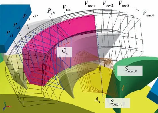
Fig.5 Illustration for determining the revolving entity Vmx.

Therefore,after setting a reasonable calculation step and performing an iteration searching,the maximum value Vmwas obtained.These geometry limitations were guaranteed by interference check provided from the CAD software.Moreover,in order to ensure the practical value of the designed electrode,three parameters were calculated here.First,the volume ratio of Vmto Vchannelwas defined as Rv,which represents the actual volume ratio removed during roughing.The other two parameters Lxand Lywere the minimum feature sizes along X direction and Y direction respectively.Lower thresholds for these three parameters were manually set before the iteration.When any parameter in the search result is lower than the set thresholds,the result would be unavailable,indicating the case may not be suitable for high-current discharge roughing(Figs.6 and 7).
3.2.Detailed electrode design steps
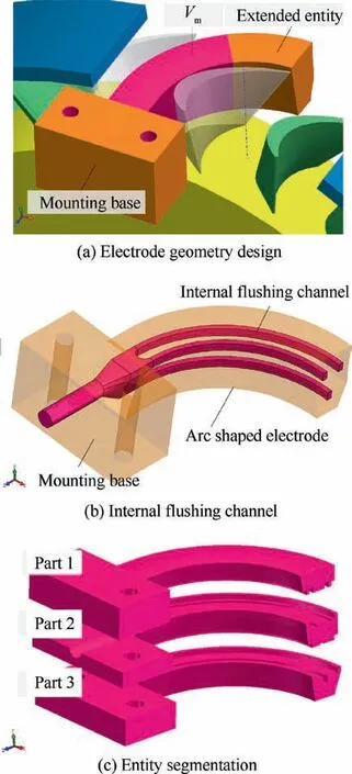
Fig.6 Schematic of electrode design steps.
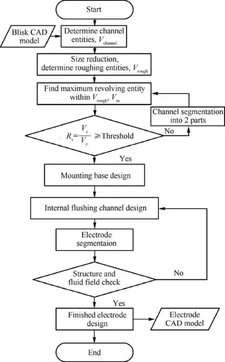
Fig.7 Workflow of proposed electrode design method.
After the maximum revolving entity Vmwas obtained,the electrode’s design needs to extend the arc-shape entity,add a mounting base,an internal flow channel,and perform physical division before complete.The flushing channel inside the electrode also needs to consider the tool wear during the machining process.Therefore,the channel also adopts a revolving geometry.
According to the rough machining’s demand for the flushing flow,the cross-section area of the flushing hole should be as large as possible to provide greater flow rate.However,opening holes in the electrode would weaken the electrode and increase the wear rate.On the other hand,the material at the corresponding position on the workpiece would not be removed,which must be solved by electrode’planetary movement.Therefore,the flushing channel adopted a hole array to solve aforementioned questions.The size of each hole is generally determined and limited by the electrode planetary movement steps during the machining.According to the given flushing pressure,the required cross-sectional area of the flushing channel was estimated to determine the number and distribution of the flushing hole array.Since the shape and size of internal flushing structure have a significant impact on the machining performance,the distribution of the flushing channel array needs the help of finite element software for CFD simulation and optimization to obtain a relatively uniform gap pressure distribution.
As for the electrode mounting base,fully considerations were given for functions such as mounting and fixing,positioning adjustment,and connection to the flushing pipeline.Finally,through a reasonable split operation,the electrode geometry was converted into several parts that are easy to be made,and the design of this entire electrode was completed.
In summary,this electrode design method includes five main steps:size reduction,maximum revolving entity extraction,internal flow channel design,mounting base design,and geometry segmentation.In some cases,the electrode entity extracted using single lcmay not meet the of removal volume for roughing.If necessary,the channel entity can be divided into two parts in the same way as the EDM electrode,and machine on both sides.
3.3.Machining trajectory planning
It is necessary to generate correct tool path corresponding with the electrode geometry to ensure the correct result for an integral shrouded blisk’s channel.The proposed electrode with revolving entity also requires circular movement of the electrode around its revolving axis during the machining to avoid overcut.Moreover,in order to achieve better dielectric fluid’s circulation and clear debris in the machining gap under violent discharges,and remove the workpiece material corresponding to the flushing hole in the meantime,it is necessary to introduce planetary movement on the main trajectory.Tool electrode’s planetary movement of ordinary EDM machines is mostly planar motion,that is,the motion range of the electrode center point is always in the same plane.Such motion would cause inconsistent in the actual remaining margin in the case of the arc-shaped electrode.
The solution is to make sure that the electrode planetary motion plane is always perpendicular to the main motion,that is,parallel to the electrode end’s surface.As shown in Fig.8,the planetary motion is always perpendicular to the main motion direction,so as to ensure that the processing channel margin is always consistent along the channel arc direction.After combining the trajectory of planetary motion and the main motion,a curved spiral shaped trajectory is obtained.The NC program was output by calculating the trajectory coordinates of the electrode mounting hole(shown with red line in Fig.8).
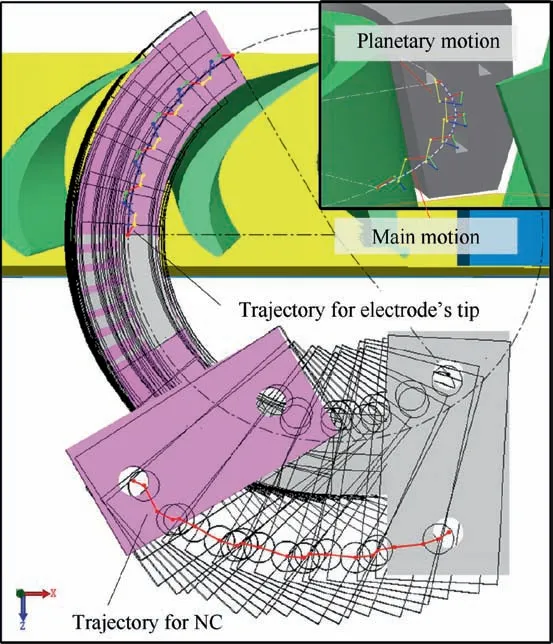
Fig.8 Illustration of circular feeding trajectory with additional planetary motion.
4.Experimental validation
In order to verify the actual performance of the electrode designed with method above,an integral cascade was taken as an example for experimental test as shown in Fig.9.The raw disk was replaced by block shaped samples for convenience.In order to analyze the difference between the efficiency of the high-current discharge roughing using this electrode and the ordinary EDM using traditional electrodes,AISI321 die steel was used for comparative analysis in this experiment.The sample 1 was finished by high-current discharge roughing on this customized machine tool.Sample 2 for comparison was made on an ordinary EDM machine tool with same technical specifications.Experiment conditions of two samples are shown in Table 1.
It should be explained that it is a common practice for researchers and manufacturers using relatively cheap steel(with machining performance similar to the actual blade materials)as an alternative material for technical improvement testing when they don’t focus on the characteristics of certain material.18,25The specific composition of AISI 321 steel is shown in Table 2.

Fig.9 Blisk and electrode geometry used for experimental verification.
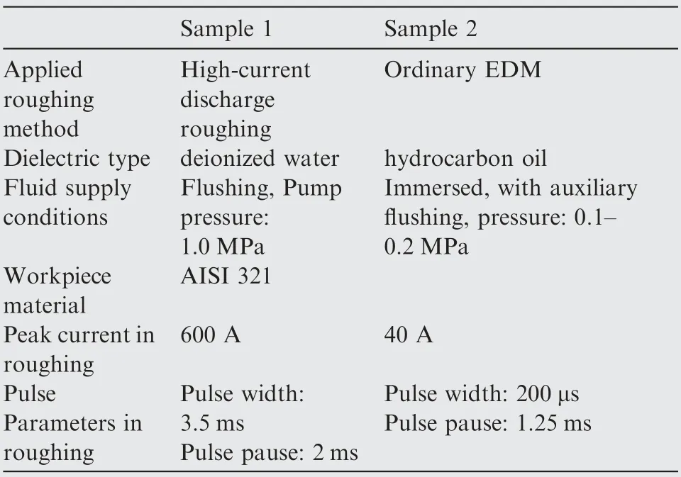
Table 1 Experimental conditions for verification samples.
Fig.10 shows the fabricated electrodes and the actual roughing operation using these electrodes.It showed that the electrode was able to effectively and stably provide the highpressure flushing required in the processing process under the high-current discharge conditions.Sample 2 was machined on an ordinary EDM platform with immersed mode.Three flow channels were provided by each sample block,and the time consumed for each channel in two modes were recorded,respectively.Average material removal rates were calculated and shown in Fig.11.
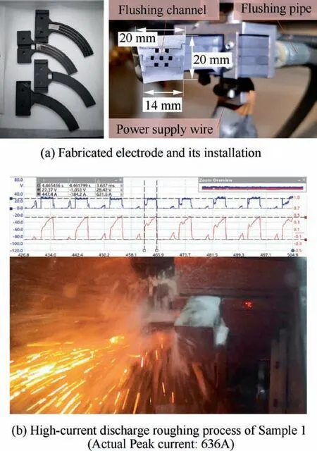
Fig.10 Experimental verification of an integral blisk’s highcurrent discharge roughing.

Table 2 Composition of AISI321 steel used in experimental verification.

Table 3 Time consumption of each channel.
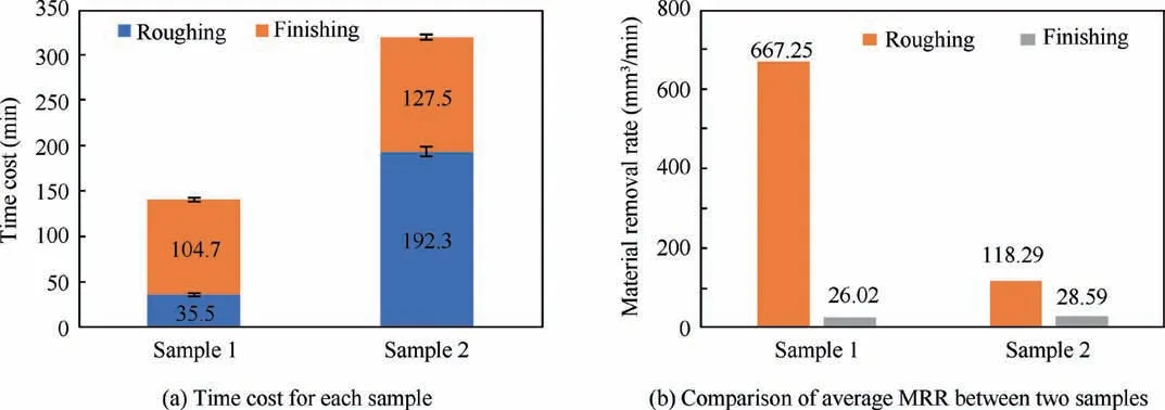
Fig.11 Comparison of machining efficiency between two samples.
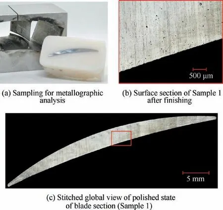
Fig.12 Blade sampling position and microscopic observation(polished state).
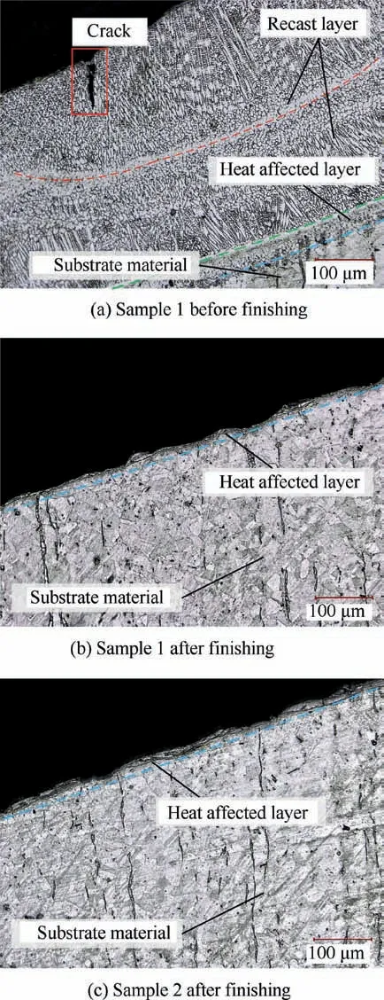
Fig.13 Metallography results of cross section on surface of Sample 1 & Sample 2.
After roughing,the finishing allowance of Sample 1 were 3-4 mm.The roughing operation took about 35 min,which was shortened to one-fifth of the ordinary EDM.Both samples used same EDM operation for finishing,but due to the slight difference in the remaining allowance,the difference of time consumed in the finishing stage is not obvious.It shows that the overall machining efficiency of this structure was significantly improved by using the high-current discharge mode.In ordinary EDM process,the gap between the channel and the electrode is very narrow before the channel was penetrated,there are numerous of debris cannot be removed from the gap in time,thus consuming the longest time.However,this stage actually has the largest machining allowance,which makes it possible to use high energy discharge for high efficiency roughing.Compared with ordinary EDM method,the overall efficiency was significant improved in hybrid machining method using high-current discharge roughing,in which the time consumption was much shortened before the channel was penetrated(Table 3).
Surface finishing of Sample 1 was performed using EDM,and the final surface obtained was shown in Fig.12.The blades were cut and metallographic analysis was done using digital microscope(KEYENCE VHX-1000).Etched by fresh aqua regia,the results were shown in Fig.13,the metallography results show that there was a 500~600μm thick recast layer on the surface of Sample 1 after high current discharge roughing,which was characterized by the columnar structures.The pits and defects on the blade surface caused by high current discharge were completely removed after finishing.The final surface quality obtained was comparable to the ordinary EDM method.The thickness of the remaining heat-affected layer(HAL)is only 10-20μm,which is easy to remove by abrasive flow machining.
5.Conclusions
By analyzing the structural characteristics of the integral shrouded blisk,a design method for roughing electrode with the largest revolving entity is proposed.Tests were carried out in the high current discharge mode in a self-designed platform,and the following conclusions can be drawn:
1)An electrode design method was proposed for integral shrouded blisk roughing.By extracting geometrical elements such as the cross-section and center line of the blisk,this method gives electrode with largest revolving entity while ensuring the roughing allowance.
2)The tool path including planetary motion was designed according to the geometry of the channel,which meets the requirement of providing additional machining gap during machining.Experimental results showed that this trajectory has guaranteed the machining stability.
3)It was proved that this electrode is able to meet the requirements of strong flushing and high wear rate’s compensation.After finishing,blades were obtained,the final surface quality obtained was comparable to the ordinary EDM method.
4)The total time consumption of machining using the high-current discharge roughing was shortened to half of that of conventional EDM,showing the machining efficiency was significantly improved.
This paper provides a high-efficiency processing method for the integral shrouded blisk.This electrode design method can be used for several types of leaf discs.In the future,further optimization and improvement in the internal flushing channel structure of the electrode and machining parameters deserve more attention.
Declaration of Competing Interest
The authors declare that they have no known competing financial interests or personal relationships that could have appeared to influence the work reported in this paper.
Acknowledgements
The authors are grateful to colleagues of Capital Aerospace Machinery Company for professional advice and helps during the experiment.This study has been funded by the Applied Technology Research and Development Projects of Hei Longjiang Province,China.(No.GA16A404).
 CHINESE JOURNAL OF AERONAUTICS2021年6期
- CHINESE JOURNAL OF AERONAUTICS的其它文章
- Performance evaluation of creep feed grinding ofγ-TiAl intermetallics with electroplated diamond wheels
- Thermomechanical coupling effect on characteristics of oxide film during ultrasonic vibration-assisted ELID grinding ZTA ceramics
- Modeling and experiment of grinding wheel axial profiles based on gear hobs
- Electrochemical machining on blisk channels with a variable feed rate mode
- Framework and development of data-driven physics based model with application in dimensional accuracy prediction in pocket milling
- Performance analysis and application on Ti-6Al-4V of micro-forging system
