Performance evaluation of creep feed grinding ofγ-TiAl intermetallics with electroplated diamond wheels
Xinxin XI,Wenfeng DING,*,Zhixin WU,Lm ANGGEI
a College of Mechanical and Electrical Engineering,Nanjing University of Aeronautics and Astronautics,Nanjing 210016,China
b Shenyang Liming Aero-Engine Co.,Ltd.,Aero-Engine Corporation of China,Shenyang 110043,China
KEYWORDS
Abstract This paper evaluates the performance of creep feed grindingγ-TiAl intermetallic(Ti-45Al-2Mn-2Nb)using electroplated diamond wheels.Firstly,a comparative analysis with the grinding results by using electroplated CBN wheels was conducted,mainly involving abrasive wheel wear behavior and maximum material removal rate below surface burn limit.It was found that the diamond wheel would produce much better grinding results including lower wheel wear rate and higher maximum material removal rate.Then the surface integrity obtained at different level of material removal rate was characterized with the utilization of the diamond wheel.The poor ductility of this γ-TiAl intermetallic material was found to have a marginal effect on the surface integrity,as no severe surface defects such as material pullout were generated during the stable wheel wear stage.For the involved operating parameters,a deformation layer was produced with~10μm or more in thickness depending on the material removal rate used.Meanwhile,a work-hardened layer extending to more than 100μm was produced with a maximum microhardness of above 520 HV0.05(bulk value 360 HV0.05).The residual stress remained compressive,with a value of above-100 MPa and even up to-500 MPa for an elevated material removal rate.Shearing chip was the main chip type,indicating good wheel sharpness in the grinding process.
1.Introduction
γ-TiAl intermetallics have high strength and favorable oxidation and creep resistance at elevated temperature of up to 750℃,with only half the density of Inconel718 nickelbased superalloy,which could provide an alternative to the nickel-based superalloy application in hot section of aero-engines.1-4For example,GEnxTMaero-engine have incorporated Ti-48Al-2Mn-2Nb alloy in the last two stages of low-pressure turbine blades,bringing a weight loss of~200 pounds.
Grinding is a key process for production of the aero-engine components with complex geometries,such as blade roots,which is capable of collectively achieving required surface integrity and dimension accuracy.5-8Unfortunately,titanium-based alloys have been considered as typical hardto-machine materials because of high strength,low thermal conductivity,as well as strong chemical affinity for carbon,nitrogen and oxygen,etc.4,8-11In comparison with conventional titanium-based alloys,such as Ti-6Al-4V,the high content of Al element inγ-TiAl intermetallics leads to a larger thermal conductivity(~22 compared to 7.5 W/m/K);4however,the outstanding strength maintenance at high temperature that originate from the long-range ordered crystalline structure,with only~5% reduction in ultimate strength at 750℃,may in part offset this advantage.
A lot of researches have been carried out into grinding features ofγ-TiAl intermetallics,involving surface grinding,12-17creep feed grinding,18-22and speed stroke grinding.23Hood,et al.17-19,23reported the grinding results of Ti-45Al-2Mn-2Nb.In surface grinding with SiC abrasive wheels,depth of cut was determined to be the most important factor to affect the grinding force,as opposed to grain size,wheel grade and wheel structure.The recorded values were 20-50 N/mm and 5-15 N/mm respectively for the normal and tangential forces within the applied grinding conditions,of which the former stays at the same level while the latter is only about a half compared with those for Ti-6Al-4V alloys.This results in a grinding force ratio of more than 3,which is approximately the level when grinding cast iron and may be attributed to the poor ductility of this kind of material.Surface roughness Ra,varying from 0.5 to 4.5μm under the given grinding parameters,was also heavily influenced by the depth of cut.The assessment of subsurface integrity also highlighted a slightly hardened layer with a maximum microhardness of 430-480 HK(bulk material 350-380 HK),without serious microstructure damage.17Through creep feed grinding,the use of SiC abrasive wheels would lead to minor surface burn and surface material fracture/pullout at grinding speed of 30 m/s,table speed of 150 mm/min and depth of cut of 1 mm.Applying vibration assistance in the grinding process was proven to be an effective solution for these problems,which would be accompanied by a reduction in grinding force by~35%,while the microhardness and microstructure alternations were reported to be nearly the same with those in conventional creep feed grinding.
When employing the electroplated diamond wheels with identical grain size,the ground surface roughness value reached up to Ra=5μm due mainly to the poor protrusion height uniformity of the abrasive grains,which contrast sharply with that for SiC abrasive wheels(~Ra=1.6μm).18However,the grinding results relating to creep feed grinding using electroplated diamond wheels demonstrated that,this grinding configuration would also be capable of producing required surface integrity for an aero-engine component.The roughing process consisted of a grinding speed of 35 m/s,table speed of 150 mm/min and depth of cut of 1 mm,together with a relatively large grain size(252μm),for the pursuit of higher grinding ratio and material removal rate,while a finer grain size(46μm)as well as associated small depth of cut(0.1 mm)were used for the finishing process to achieve acceptable surface integrity.The roughing process would give rise to a large grinding ratio of above 100,at the cost of generating cracks and material fracture/pullout extending to~20μm deep on the ground surface;the finishing process would removal this defect layer and produce a smooth ground surface of~Ra=0.3μm and an almost flat microhardness-distance profile.19Feasibility of speed stroke grinding was also confirmed by process modelling and subsequent experimental verification.Despite high grinding speed(125 and 160 m/s)and small depth of cut(~20μm),the use of very high table speed(50-200 m/min)would reduce the sliding length for per unit volume of material removal while guaranteeing a considerable material removal rate,thus resulting in a low specific grinding energy and corresponding reduced ground surface temperature.As a result,the surface residual stress condition generally remained compressive.Nevertheless,it is important to note that,surface cracks were found on the ground surface with the use of grinding speed of 125 m/s,table speed of 200 m/min and depth of cut of 18μm,albeit with a generated compressive residual stress of~-600 MPa.This suggests that,not only a certain degree of tensile residual stress but also an enhanced compressive one can incur the surface crack,and the main cause was the nonuniform deformation under compressive load between theγ-TiAl phase with relatively high fracture toughness and theα2-Ti3Al phase featuring high hardness and strength.23
Ti-45Al-8Nb-0.2C is another extensively investigated intermetallic in grinding researches.20-22The comparative study at identical grinding parameters using SiC abrasives showed a 9 times higher grinding ratio for this alloy when compared to Ti-6Al-4V alloy.The preferred parameters for the maximum grinding ratio of~30 were recommended as a low grinding speed of 15 m/s,a table speed of 150 mm/min and a depth of cut of 1.25 mm,under which the ground surface roughness was Ra=1.1μm.Raising the grinding speed would lower the Ra value,but the surface burn became inevitable.Under the abovementioned condition,the grinding induced damages included intermittent deformation of the lamellae within 2-4μm with no visible cracks and material fracture/pullout.In order to achieve a larger material removal rate,increasing the table speed seems more preferable,because surface cracking is more sensitive to the depth of cut.The utilization of vitrified superabrasive wheels,even with significantly finer grains of 91μm,would lead to a~10 folds larger grinding ratio than the SiC abrasive wheels under similar grinding conditions.The lower porosity rate of the superabrasive wheels was expected to have contributed to this.21However,the combination of small grain size and lower level of porosity rate was an indicator of poor cooling condition in the grinding zone,which is unfavorable for the enhancement of material removal rate.
With the development of abrasive machining technology,some useful tools have been adopted for further exploring machining mechanisms,such as advanced testing techniques(e.g.X-ray diffraction,backscatter electron microscopy,electron backscatter diffraction and transmission electron microscopy),24specially-developed experimental setup/method(e.g.single grain scratching/grinding)25and finite element simulation.26For instance,Zhang et al.25,27analyzed the surface layer changes during diamond scratching of silicon wafers based on a developed grinder,which can facilitate a cutting speed in m/s.This is three to six orders magnitude higher than nanoscratching conducted at mm/s orμm/s and is in a comparable level to that of grinding,which enlightens a new route to investigate fundamental grinding behavior of titanium-based alloys.They also produced a very smooth machined surface of Ti-6Al-4V titanium alloy,with a surface roughness of less than 1 nm,by using a novel environment-friendly chemical mechanical polishing slurry.28
For the grinding processes of titanium-based alloys,the use of single layer superabrasive wheel can significantly improve the material removal rate due to their high grain protrusion and outstanding thermal conductivity.29-31At present,the involved material removal rate in the stable wheel wear stage has been limited to 2.5 mm3/(mm·s),a relatively small value for this type of abrasive wheel.In addition,the grinding performance differences between diamond and CBN abrasives are still unclear.
In the current study,the preference between diamond and CBN abrasives for creep feed grinding ofγ-TiAl intermetallic is determined according mainly to the wheel wear behavior and maximum material removal rate below surface burn limit.The ground surface integrity alternations at varied material removal rate are analyzed in terms of surface morphology,surface roughness,microhardness,metallographic structure and residual stress.The grinding chip characteristics are also discussed in order to promote a better understanding of the grinding process ofγ-TiAl intermetallics.
2.Experimental details
2.1.Workpiece material
The workpiece material used was Ti-45Al-2Mn-2Nb(at.%)intermetallic bars prepared by casting,following hot isostatic pressing at a temperature of 1260℃and pressure of 170 MPa for 4 h,and a final heat treatment process under 950-1000℃for 8 h.The preparation procedure produced a nearly fully lamellar structure(Fig.1).Small quantity of B element was also contained in the form of fine TiB2whiskers to improve the mechanical properties.Main workpiece material properties were summarized in Table 1.Sample blocks sized 30 mm×25 mm×5 mm were obtained for the grinding trails via wire electrical discharge machining.
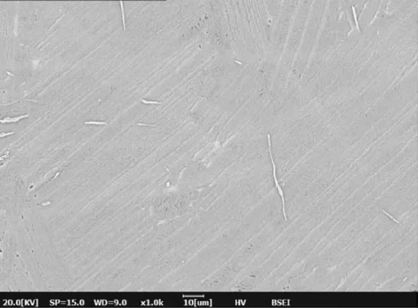
Fig.1 Metallographic structure of Ti-45Al-2Mn-2Nb intermetallic used for present grinding experiment.
2.2.Experimental procedure and conditions
All the grinding trails were performed on a BLOHM Profimat MT 408 surface grinding machine in the down-grinding mode.Grinding setup is shown in Fig.2.Grinding fluid was Castrol Syntilo 9954 solution with a concentration of 5% and was supplied with a pressure of 1.5 MPa.Two electroplated CBN wheels and two electroplated diamond wheels were used from the as-produced state.They had a diameter of 400 mm and width of 10 mm,and the grain size(~200μm)and density were kept comparable to yield fair conclusions.The experiment consisted of two parts,with a constant grinding speed of 30 m/s,a typical value for grinding of titanium alloys.4The first part focused on the progressive wheel wear process using table speed vw=150 mm/min and depth of cut ap=1 mm.The radial wheel wear was periodically recorded by grinding a stainless steel razor blade.32,33Meanwhile,the grinding force for each grinding pass was captured utilizing a Kistler force transducer coupled into the worktable of the grinding machine,by subtracting the sparkout force from the total measured value to eliminate the effect of the grinding fluid.Surface roughness Ra was also recorded using a Mahrsurf PS1 surface roughness tester(cut length:0.8 mm).The second part,starting with a new abrasive wheel,focused on remaining grinding performance in the stable wheel wear stage.The abrasive wheel experienced the initial wear transient with the same table speed and depth of cut as those in the first part.Parameters combination with table speed ranging 150-720 mm/min and depth of cut changing from 0.9 to 1.8 mm were supplemented for the determination of maximum material removal rate,and three levels of material removal rate(Table 2)were selected to cover the ranges of interest for the evaluation of grinding induced surface integrity.
After grinding,the grinding chips were obtained through following steps:I)collecting the grinding fluid remaining on the worktable using a beaker,II)keeping the beaker unmoved for 30 minutes to make sure the grinding chips are deposited on the bottom,III)pumping out the grinding fluid and ultrasonically cleaning the grinding chips with ethanol,and IV)drying the grinding chips and sticking them out using conductive tape.Grinding chips,ground surface and wheel surface were analyzed with a COXEM EM-20 scanning electron microscopy(SEM)under the secondary electron mode,while the metallographic structure was observed under the backscattered electron mode(etching solution:2% HF and 10% HNO3;immersion time:7 s).Microhardness profile was achieved using a HXS-1000A microhardness tester(Vickers indenter;50 g load;dwell time:15 s).Residual stress of the ground surface was measured in the directions both parallel(σ‖)and perpendicular(σ⊥)to the table speed,on a Proto-LXRD X-ray stress analyzer using sin2ψmethod with Cu-Kαradiation.The voltage and current used were 20 kV and 30 mA respectively.

Table 1 Room-temperature properties of Ti-45Al-2Mn-2Nb intermetallic used.
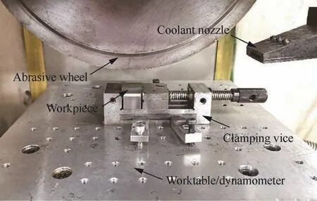
Fig.2 Grinding setup in present study.

Table 2 Three levels of material removal rate for evaluation of ground surface integrity.
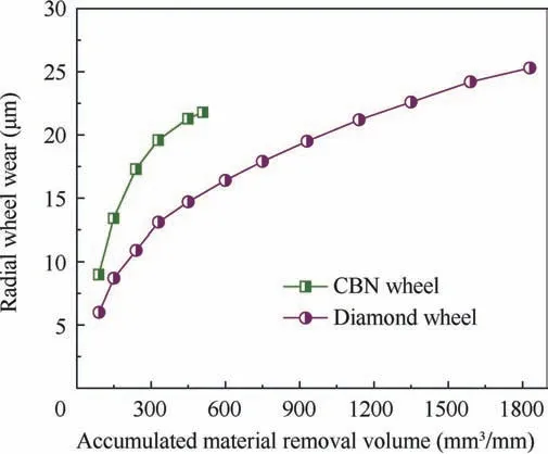
Fig.3 Radial wheel wear as a result of accumulated material removal volume(vw=150 mm/min and ap=1 mm).
3.Results and discussion
3.1.Comparative analysis of grinding results using diamond and CBN abrasive wheels
3.1.1.Wheel wear and its effects on grinding force and surface roughness
The measurement results of radial wheel wear are plotted in Fig.3.With the use of CBN wheel,surface burn was encountered when the accumulated material removal volume with unit width of abrasive wheel Q′warrived at 510 mm3/mm.Therefore,no further experimental results were given.For both types of abrasive wheels,the abrasive wheel underwent an initial wear transient,with a loss in radius of 17.3 and 10.9μm in the first 240 mm3/mm accumulated material removal for the CBN and diamond wheels respectively.With the grinding process proceeding,the wheel wear rate became slower,and the values were 4μm for the CBN wheel and 3.8μm for the diamond wheel in the subsequent 210 mm3/mm accumulated material removal.The reason for the faster wear rate of CBN wheel is mainly due to the inferior hardness and thermal conductivity.
Microscopy observations of the wheel surface suggest grain fracture and pullout as the main wear mechanisms for these two kinds of abrasive wheels,as shown in Fig.4.Cleavage facets on the fractured grains are indictive of micro or macro fracture.Compared with attrition wear,this wear pattern would cause smaller increase in grinding force and power.Grain pullout was expected to occur more frequently in the initial wear transient.In this stage,only those over-protruded grains can be involved in the material removal process.High grinding loads acting on each individual grain because of larger undeformed chip thickness may lead to grain pullout.According to the research results of Shi and Malkin,33grain pullout contributes to 60%-80% of the radial wheel wear in the initial wear transient.With more grinding,some inactive grains can be activated and introduced to the cutting process,and the wheel wear rate is therefore reduced(Fig.3).Adherent workpiece material around the cutting edge on the grain tips was also evident.This part of material can enlarge the contact area between the abrasive grain and the workpiece,giving rise to higher probability of grain fracture or pullout.
As well known,the grinding force is closely related to the wheel wear process.Measured force values are summarized in Fig.5 as a function of Q′w.The grinding forces revealed a gradual increase with increasing Q′w,with a rapid growth at first and a relatively moderate one thereafter(Fig.5(a)and(b)).For example,the as-produced(Q′w=0)abrasive wheel induced a normal grinding force of 8.5 and 12.2 N/mm for the diamond and CBN wheels respectively,and the values were enhanced to 54.6 and 70.5 N/mm for Q′w=510 mm3/mm.This is very similar to the trend for the radial wheel wear(Fig.3)and can be attributed to the increasing number of active grains that would lead to larger contact area between the wheel and the workpiece.33In addition,it is important to note that the grinding force ratio when creep feed grinding Ti-45Al-2Mn-2Nb intermetallic is significantly larger than that when grinding the conventional titanium alloys(Fig.5(c)),which generally has a value of less than 2.34The poor ductility of this kind of material may be account for this,as less workpiece material can be accumulated ahead of the cutting grain,which requires smaller tangential force to removal this part of material.
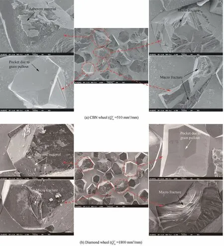
Fig.4 Detailed morphology for abrasive wheel surface(vw=150 mm/min and ap=1 mm).
Ground surface roughness can also be heavily affected by the wheel wear process.The recorded surface roughness Ra values dropped from 2.49 and 2.37μm for the as-produced CBN and diamond wheels respectively to 0.8 and 1.26μm for Q′w=510 mm3/mm(Fig.6).After removing 1800 mm3/mm of workpiece material,the Ra value for the diamond wheel further dropped to 0.8μm,which can generally meet the roughness requirement for some machined surfaces on aero-engine components,such as low-pressure turbine blades.This agrees well with the wheel wear rate results and is a result of the related improvement of grain protrusion uniformity.33,35
3.1.2.Maximum material removal rate
Optical images of the ground surface after each grinding pass were taken using digital camera in order to reflect the macro changes(e.g.surface burn).The images reveal no damage with vw=300 mm/min and ap=1.2 mm when employing the CBN wheel(Fig.7(a)),while grinding burn can be found with a raised table speed of 360 mm/min(Fig.7b)and the parameters in Fig.7(c)and(d).This yields a maximum material removal rate below burn limit of more than 6 mm3/(mm·s).Similarly,the value for the diamond wheel is raised to 12 mm3/(mm·s)(Fig.7(e)-(h)),and the improvement can be ascribed to the superior thermal conductivity and wear resistance of the diamond abrasive.

Fig.5 Grinding force and force ratio(vw=150 mm/min and ap=1 mm).
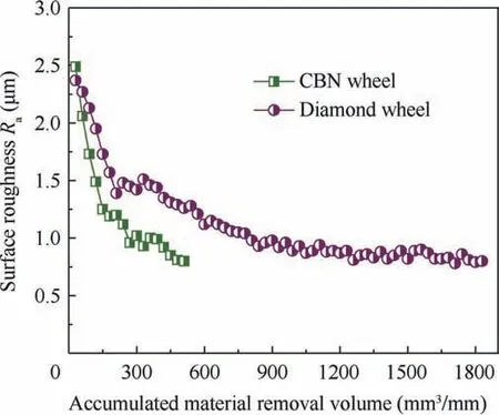
Fig.6 Ground surface roughness at varied accumulated material removal volume.
Considering the previously-stated comparative analysis,it is quite reasonable to conclude that the electroplated diamond wheels would promote better grinding performance featuring lower wheel wear rate and higher material removal rate when comparing to the electroplated CBN ones.Therefore,the remaining grinding performance was accessed using only the diamond wheel.
3.2.Ground surface integrity
3.2.1.Surface morphology and roughness
Ground surface observations under varied grinding conditions highlight that ground surface of Ti-45Al-2Mn-2Nb intermetallic using electroplated diamond wheels consists mainly of grinding striations,smooth area,uneven and irregular area,microcracks and material pullout,with no evident smearing material and deposited debris(Fig.8).The microcracks and material pullout have been barely found when grinding the conventional titanium alloys,e.g.Ti-6Al-4V alloy unless on a burnout ground surface under unoptimized conditions,8which indicates that the poor ductility and high crack growth rate may be responsible for these defects.In addition,they were generally only found on the ground surface in the early stage of the wheel life due to the extremely large undeformed chip thickness by over-protruded cutting grains(Fig.8(a)and(b)),35and could rarely be observed during the stable wheel wear stage(Fig.8(c)),even at much higher material removal rate(Fig.8(f)).This on one hand emphasizes the necessity of wheel conditioning for a newly used electroplated abrasive wheel.On the other hand,unlike that for cutting,the poor ductility ofγ-TiAl intermetallic seems not a serious problem for creep feed grinding.The uneven and irregular area always containing some tiny microcracks(Fig.8(e))is reported to be caused by the limited penetration depth into the workpiece material of some cutting grains.36
Surface roughness Ra at different material removal rate is plotted in Fig.9.For Test 1 and Test 3,the average value of Rawere 1.03μm and 1.09μm respectively,which indicates that the material removal rate has exerted a marginal influence on the surface roughness.In fact,apart from the average value of undeformed chip thickness,the ground surface roughness using single layer electroplated wheels is also significantly affected by its standard deviation,which is an indicator of the grain protrusion uniformity of an abrasive wheel.33,35The larger the standard deviation,the rougher the ground surface.Increasing material removal rate can give rise to larger average value and standard deviation of the undeformed chip thickness,thus exerting negligible influence on the ground surface roughness.
3.2.2.Metallographic structure
The workpiece material suffers from mechanical and thermal loads during grinding,which may induce some metallographic alternations,such as recrystallized layer,white layer and grain deformation.24SEM images of the workpiece subsurface show evident deformed grain,which would further reduce the ductility of the workpiece.The deformation layer extended to~10μm for Test 1(Fig.10(a)),and was increased to above 20μm for Test 3(Fig.10(c))due to heavier grinding loads.
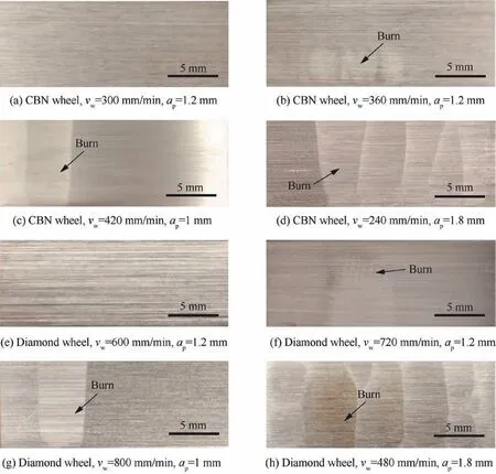
Fig.7 Optical images of ground surface.
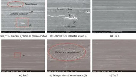
Fig.8 SEM observations of ground surface.
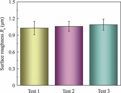
Fig.9 Ground surface roughness at different material removal rate.
3.2.3.Microhardness
During grinding,the formation of deformed grain is always companied by the increase in microhardness,namely,workhardening.24As shown in Fig.11,for Test 1,the thickness of the work-hardened layer was~100μm,with a maximum microhardness of 520 HV0.05(bulk value 360 HV0.05).Increasing the operating parameters to Test 3 would result in a hardened layer thickness of above 200μm,with a maximum microhardness of 600 HV0.05.
3.2.4.Residual stress
Residual stress plays a very important role in affecting the fatigue life of a ground component.For the grinding conditions in the current study,compressive stress would be formed on the ground surface(Fig.12).The compressive stress was-125 MPa alone the table speed direction and-221 MPa in the perpendicular direction for Test 1.For an enhanced material removal rate,i.e.Test 3,they were increased to-251 MPa and-517 MPa respectively,which is due to the more serious degree of grain deformation.24
3.3.Chip morphology

Fig.10 Grinding-induced metallographic structure changes.
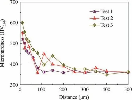
Fig.11 Microhardness of ground surface/subsurface layer.
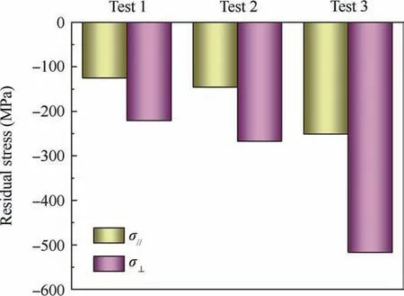
Fig.12 Residual stress of ground surface.
Chip formation in grinding is a result of workpiece properties,grinding parameters,wheel conditions and coolant supply,etc.and relates closely to grinding power,wheel wear and surface integrity.For the grinding of metals,a debris generally falls into one of the following categories:flowing,blocky,shearing,slice,knife,ripping and melting chips.37,38As shown in Fig.13,the prevailing chip type during creep feed grinding of Ti-45Al-2Mn-2Nb intermetallic was shearing chip,with few more slender flowing chips,indicating good tool sharpness in the grinding process.38This is similar to the grinding chip characteristics when grinding some alloys with good ductility(e.g.Inconel 718 nickel-based superalloy37and 100Cr6 steel,38which may further indicate that the poor ductility ofγ-TiAl intermetallic is not a serious problem in creep feed grinding.The shearing chip had relatively regular‘‘sawtooth”on the free surface,with~10μm in width under the given grinding conditions(Fig.13(b)).Some of the chip had smooth rear face,whilst some others had several micro grooves on the rear face,which can be attributed to the diverse geometry of the cutting edges on the abrasive grains.The grooved rear face was always accompanied by one or two fractured edge(Fig.13(c)and(d)).
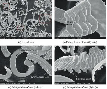
Fig.13 Grinding chip morphology(vw=300 mm/min,ap=0.9 mm).
4.Conclusions
Features of creep feed grinding of Ti-45Al-2Mn-2Nb intermetallic by mainly using electroplated diamond wheels were discussed,including wheel wear behavior,surface integrity and chip morphology.Main findings are summarized as follows:
(1)The electroplated diamond wheels are more suitable for creep feed grinding Ti-45Al-2Mn-2Nb intermetallic when comparing to the electroplated CBN ones,due to higher material removal rate and lower wheel wear rate.The diamond wheel would give a maximum material removal rate below burn limit of up to 12 mm3/(mm·s),while the value would only be about a half for the CBN wheel.Abrasive grain fracture and pullout were the main wear patterns for the both kinds of abrasive wheels.The trends of changes in grinding force and surface roughness coincided well with the wheel wear process.
(2)Material pullout generally only appeared in the early stage of the wheel life.For vw=150 mm/min and ap=1 mm,a grain deformation layer having a thickness of~10μm was produced,together with a work-hardened layer extending to over 100μm.The compressive stress on the ground surface was above-100 MPa.Increasing the material removal rate would raise these values.
(3)Shearing chip was found to be the main chip type,further indicating that the poor ductility ofγ-TiAl intermetallic may not be a serious problem in creep feed grinding.The main obstacle to high efficiency grinding of this kind of material is still possible surface burn at elevated material removal rate.
Acknowledgments
This work was financially supported by the National Natural Science Foundation of China(Nos.51921003 and 51775275),the Major Special Projects of Aero-engine and Gas Turbine of China(2017-VII-0002-0095),the Six Talents Summit Project in Jiangsu Province of China(No.JXQC-002)and the Postgraduate Research & Practice Innovation Program of Jiangsu Province(No.KYCX18_0256).
 CHINESE JOURNAL OF AERONAUTICS2021年6期
- CHINESE JOURNAL OF AERONAUTICS的其它文章
- Thermomechanical coupling effect on characteristics of oxide film during ultrasonic vibration-assisted ELID grinding ZTA ceramics
- Modeling and experiment of grinding wheel axial profiles based on gear hobs
- Electrochemical machining on blisk channels with a variable feed rate mode
- Framework and development of data-driven physics based model with application in dimensional accuracy prediction in pocket milling
- Electrode design using revolving entity extraction for high-efficiency electric discharge machining of integral shrouded blisk
- Performance analysis and application on Ti-6Al-4V of micro-forging system
