Electrochemical machining on blisk channels with a variable feed rate mode
Jing WANG,Zhengyang XU,Jingtao WANG,Di ZHU
National Key Laboratory of Science and Technology on Helicopter Transmission,Nanjing University of Aeronautics and Astronautics,Nanjing 210016,China
KEYWORDS
Abstract Electrochemical machining(ECM)is an economical and effective method for blisk manufacturing and includes two steps:channel machining and profile machining.The allowance distribution after the channel machining will directly affect the profile machining.Therefore,to improve the uniformity of allowance distribution in the machining of channels,a method that incorporates a variable feed rate mode is developed.During the machining process,the feed rates are dynamically changed according to the needs of the side gap at the different feed depths.As a result,the side gaps at the different feed depths vary,contributing to a decrease in the allowance difference.In this study,the dissolution processes of a blisk channel are simulated using different feed rates,and prediction profiles are obtained.Based on the prediction profiles,the relationship among the feed rate,feed depth,and side gap is established.Then,the feed rates at different feed depths are adjusted according to the relationship.In addition,contrast experiments are conducted.Compared with blisk channel ECM using a constant feed rate of 1 mm/min,using the variable feed rate decreases the allowance differences in the convex and concave parts by 62.2%and 67.4%,respectively.This indicates that using the variable feed rate in the ECM process for a blisk channel is feasible and efficient.
1.Introduction
As the core components of an aerospace engine,blisks greatly improve the thrust-weight ratio and working efficiency of the aerospace engine.However,nickel-based superalloys,titanium alloys,and other difficult-to-machine materials are widely used in blisks,and the shapes of blisks are extremely distorted and complicated.1,2Moreover,the machining accuracy and surface quality requirements for blisks are very strict.Therefore,it is very difficult to machine blisks.3-7In view of these difficulties,many machining technologies have been applied,such as linear friction welding,8numerical control milling,9-11electron beam machining,12,13electrochemical machining(ECM),and electrical discharge machining.14ECM has outstanding advantages as compared with other methods of blisk machining,such as avoidance of tool wear,high machining efficiency,and low cost,and it has become one of the main methods of blisk machining.15-17
There has been a significant amount of research on ECM for blisks.Fujisawa et al.18constructed a simulation model for a blade forming process,and comprehensively considered the effects of the material dissolution process,electrolyte flow field,bubbles,electrochemical reaction heat,and other factors on the electrochemical forming process.Tang and Gan19established a three-dimensional flow field simulation model for improving the efficiency of cathode design and reducing the cathode correction time in the ECM of closed blisks.Zhu et al.20presented a dynamic additional electrolyte flow for improving the stability in the ECM process of blisks.Chen et al.21optimized machining parameters for improving the surface quality in the ECM of blisk blades made of Ti60 alloy.Zhang et al.22proposed a cathode designing method to avoid electrodes’interference during the ECM process of blisks.Tang et al.23optimized the structure and shape of the cathode by the flow field simulation for improving the precision and efficiency in the ECM of closed blisks.Yao et al.24developed a thin hollow cathode for the ECM of complex structures.Ernst et al.25presented an inverse approach for the tool shape simulation for the ECM of a jet engine vane to shorten the tool development procedure.Wang et al.26proposed a method of the ECM with tangential feeding to improve the accuracy of the blade leading/trailing edges.
Blisk ECM includes two steps:channel machining and profile machining.27Channel machining is the first step in the ECM process for blisks.The allowance distribution after the channel machining has an important influence on the subsequent precision of the ECM.According to the concept of genetic errors in ECM,any unevenness in blisk channel machining will be transferred to the subsequent profile machining.If the allowance difference of the blisk channel machining is large,there will be an insufficient minimal allowance to eliminate this difference in the profile machining,and the accuracy of final blade profiles will be decreased.28Hence,channel machining is a key step in the ECM of blisks.Xu et al.29applied a radially feeding electrode in ECM for blisk channels,and blisk channels with low allowance difference were successfully machined.Zhang et al.30designed an extended cathode for removing the small radius formed by blisk channel ECM based on an equal-thickness cathode.Through the experiment with the extended cathode,the small radius disappeared,and the surface quality of machined blisk channel was improved.Zhang et al.31proposed a method for blisk channel machining and developed a spiral feeding ECM,in which a cathode rotated around an axis while feeding radially.Compared with a radial feeding ECM,the allowance difference of machined blisk channel was decreased.
The current methods in blisk channel ECM have made remarkable improvements in enhancing the machining accuracy and quality.However,these methods still leave much to be desired,especially in allowance uniformity.In particular,the feed rate is a crucial factor in the ECM process of a blisk channel.When it is low,the machining time is increased and the amount of material removed on the side of the channel is increased,contributing to an increase in the side gap.In contrast,when the feed rate is high,the machining time is shortened and the amount of material removed on the side of the channel is decreased,contributing to a decrease in the side gap.By dynamically adjusting the feed rate and changing the side gaps at different depth positions,the machined channel can be made more consistent with an ideal model,improving the uniformity of the allowance.Thus,this study presents an ECM method for blisk channels with a variable feed rate mode.A cathode feeds towards a workpiece with a variable feed rate,thereby improving the allowance uniformity of the machined blisk channel.Then,simulations of the dissolution process of the blisk channel using different feed rates are conducted to analyse the relationship among the feed rate,feed depth,and side gap.Furthermore,an optimization strategy is obtained for the variable feed rate,and experimental studies are conducted to verify the effectiveness of this method.
2.Description of the method
Fig.1 shows a schematic diagram of ECM process for blisk channels.During the process,the cathode feeds from an initial position to the hub along a certain feed direction,which is designed according to the shape of the blade model.The blisk channels are sequentially machined on the workpiece by electrochemical reaction.Three-dimensional models of a standard blisk channel(i.e.the channel between adjacent blade models)and a blisk channel machined by ECM with a constant feed rate are shown in Fig.2(a).Section A,located in the middle of the workpiece,is selected to show the geometry of the blisk channel,and a sectional view is displayed in Fig.2(b).The shape of a standard blisk channel is complex,in that the width between the convex part and concave part decreases gradually from the tip to the root in a nonlinear trend.However,for the shape of a blisk channel machined by ECM with a constant feed rate,the width between the convex and concave parts changes little along the feed direction,which is different from the shape of a standard blisk channel.As shown in Fig.2(b),there is excessive allowance at the tip of the blade model,and insufficient allowance at the root.Such an allowance distribution will lead to a large allowance difference,causing difficulties in subsequent profile machining.Therefore,to decrease the allowance difference,a novel method comprising a variable feed rate mode is applied in ECM for machining the blisk channel.
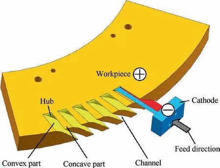
Fig.1 Schematic diagram of electrochemical machining(ECM)process of blisk channels.
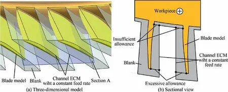
Fig.2 Schematic diagram of blade models and blisk channels machined by ECM with a constant feed rate.
In the ECM process of a blisk channel with a variable feed rate,the feed rates are changed according to the widths of the channel at different depth positions.For example,as shown in Fig.3(a),in an initial stage,the width between the convex part and concave part is wide;correspondingly,the amount of material removal amount is large.According to electrochemical theory,a low feed rate will lead to a large side gap,contributing to an increase in the amount of material removal.32In contrast,as shown in Fig.3(b),in the final stage,the width between the convex part and concave part is narrow;correspondingly,the amount of material removal is small.According to electrochemical theory,a high feed rate will lead to a small side gap,contributing to a decrease in the amount of material removal.Thus,based on a width change of the standard blisk channel,the feed rate is adjusted and the side gap is changed,such that the amount of material removal at the blade tip is increased and the final machining width becomes wide,and such that the amount of material removal at the blade root is decreased and the final machining width becomes narrow.As a result,the allowance difference of the machined blisk channel is decreased.
3.Establishment of optimization strategy for variable feed rate
3.1.Simulations of the dissolution process of blisk channel
To obtain prediction profiles under different feed rates,the dissolution processes of the blisk channel are simulated.Section A in Fig.2(a)is selected for intercepting the cathode and workpiece,and the section profile is used as a two-dimensional geometric model for the blisk channel ECM,as shown in Fig.4.In the geometric model,b is the width of the cathode cutting edge,Δiis the initial gap,and l is the length of the front surface of the cathode surface.
To simplify the simulation process,the following assumptions are made:
(1)the influence of the machining products is neglected;
(2)the cathode and workpiece are defined as an equipotential surface;
(3)Ohm’s law holds for the surfaces of the workpiece and cathode,and the electrolyte in the entire machining gap;and
(4)the machining parameters do not change with time but are only functions of the position.
The mathematical model is established as follows:33,34

The boundary conditions are set as follows:
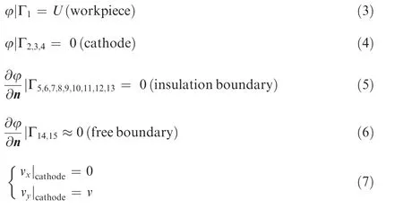
In the above,φis the electric potential,vwis the dissolved velocity of the workpiece,ηis the current efficiency,ωis the volumetric electrochemical equivalent,i is the current density,κis the electrolyte conductivity,E is the electric field intensity,U is the machining voltage,and n is the normal vector of the unit plane.
Table 1 lists the simulation conditions.The dynamic simulation processes are performed after the boundaries and simulation conditions are set.
Fig.5 shows the simulation results of the electric field distribution cloud for the feed rates of 0.4,0.6,0.8,1.0,1.2,1.4,1.6,and 1.8 mm/min.The machining gap(i.e.the frontal gap)between the hub and the front end of cathode,side gap,and machining area are shown in Fig.5(a).From the simulation results,it can be seen that the machining gap is decreased with an increasing feed rate.Due to the increase of the feed rate,the machining time is shortened and the amount of material removed on the side of the channel is decreased,contributing to a decrease in the side gap.The current density in the machining area is increased with a decreasing machining gap,27and a smaller machining gap can be obtained by increasing feed rate,and thus the current density in the machining area is increased with an increasing feed rate.Therefore,increasing the feed rate is conducive to the rapid erosion of the workpiece materials,leading to the narrowing of the width of the machined blisk channels.In contrast,decreasing the feed rate is conducive to the slow erosion of the workpiece materials,leading to the widening of the width of the machined blisk channels.
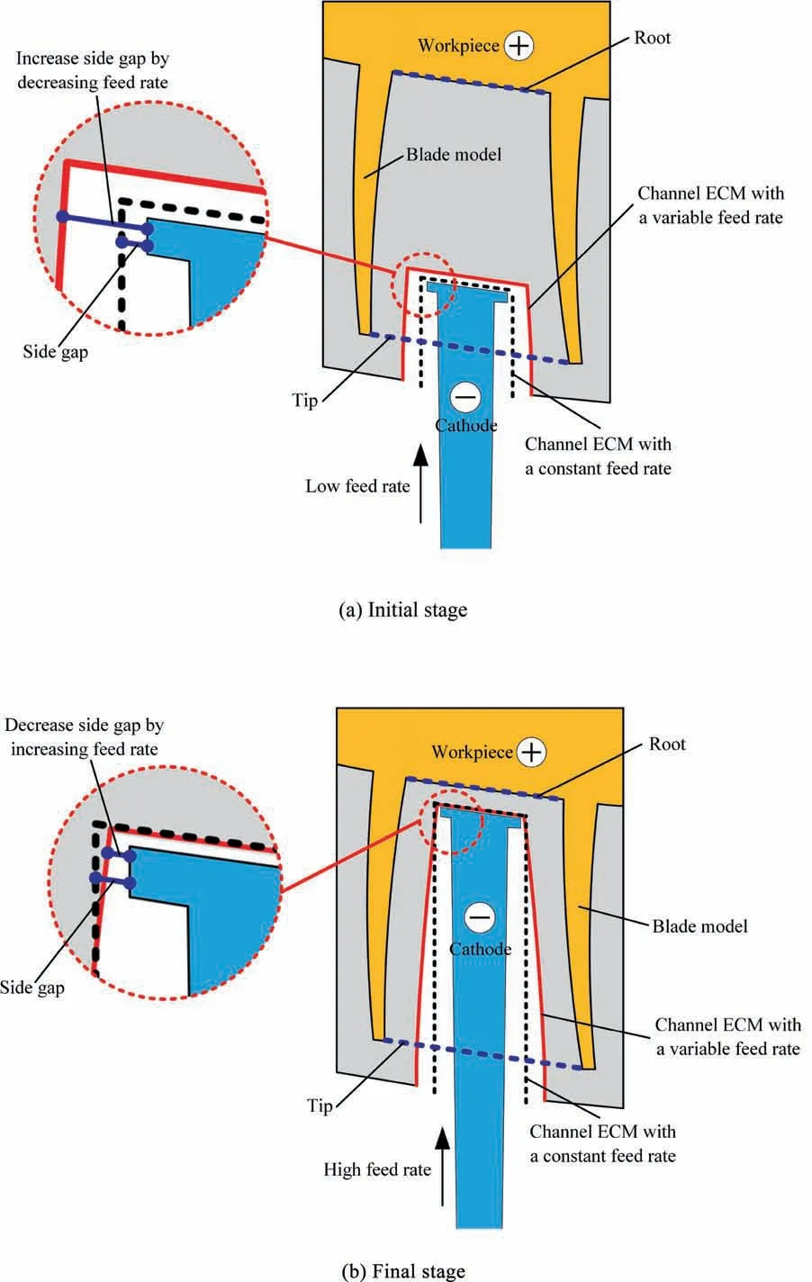
Fig.3 Schematic diagram of two stages of ECM process of a blisk channel with a variable feed rate.
3.2.Establishment of relationship among feed rate,feed depth,and side gap
The optimization strategy for the variable feed rate can be obtained using the following method.First,the dissolution processes of the blisk channel are simulated using different feed rates,and prediction profiles are obtained.Second,based on the simulation results,the relationship among the feed rate,feed depth,and side gap is obtained.A two-dimensional polynomial equation is used to define the relationship.In the equation,the feed rate is a dependent variable,and the feed depth and side gap are independent variables.Different feed rates can be achieved by varying the feed depth and side gap.Third,to obtain the varied feed rate,the ECM process of the blisk channel is divided into several stages.At each stage,the corresponding feed rate is obtained by substituting the feed depth and ideal side gap value into the equation.Finally,the optimization strategy for the variable feed rate is achieved by combining the feed rates of different stages.
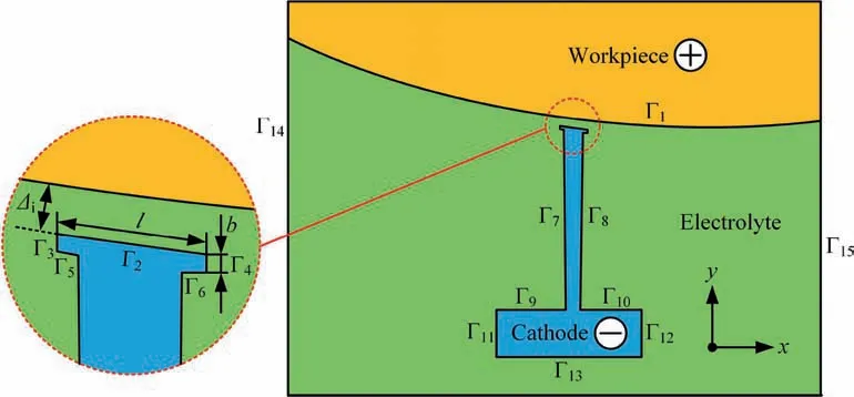
Fig.4 Two-dimensional geometric model.

Table 1 Simulation conditions.
Fig.6 shows the ECM process of a blisk channel with a constant feed rate in a stage.The desired profile of the blisk channel machined is obtained by offsetting the profile of a standard blisk channel by a certain distanceδ.l represents the length of the front surface of the cathode.Δsaand warepresent the actual side gap and actual machining width under the machining conditions of feed rate v and feed depth d,respectively.It is assumed that the conductivity of the electrolyte remains constant during the ECM process.In the stable state,the value of the actual side gapΔsacan be described as follows:

whereΔsiand wirepresent the ideal side gap and ideal machining width,respectively.The value of the ideal side gapΔsican be described as follows:

According to Fig.6,with a constant feed rate,it is difficult to ensure that the actual machining width waat each feed depth is consistent with the ideal machining width wi.Moreover,the actual side gapΔsais not equal to the ideal side gapΔsi.It is necessary to change the feed rate v of the cathode tool for adjusting the amount of material removal on the side of the channel,so that the actual side gapΔsais as consistent as possible with the ideal side gapΔsi.Thus,the relationship among the feed rate v,feed depth d,and actual side gapΔsashould be established.
The prediction profiles of the channel for different feed rates are obtained by the simulations described above,and are shown in Fig.7.Using the prediction profiles of the channel,the simulated machining widths under the varied feed rates and feed depths are measured.Then,the distributions of the simulated side gaps under different feed rates are obtained using Eq.(8).The data are listed in Table 2.The simulation values of both the machining width and side gap are used to establish the optimization strategy.
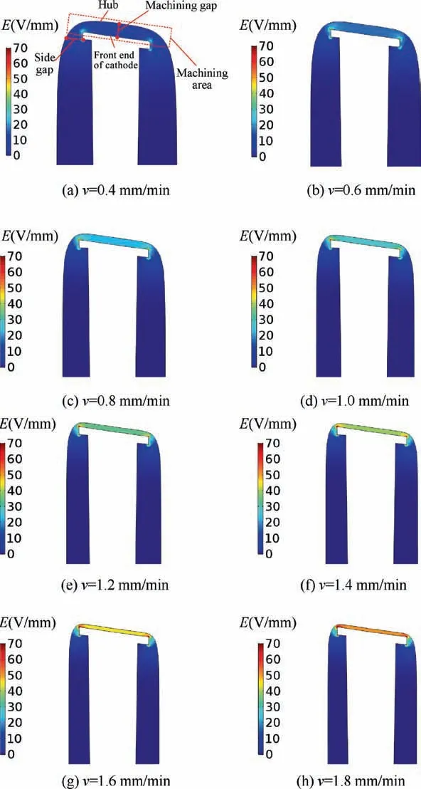
Fig.5 Nephograms of electric field intensity on a machining area with different feed rates.
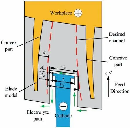
Fig.6 Schematic diagram of ECM process of a blisk channel with a constant feed rate in a stage.
According to the simulation data,several curves regarding the variation of the actual side gap with respect to the feed depth under different feed rates are obtained,as shown in Fig.8.The feed rate ranges from 0.4 to 1.8 mm/min,and the increment is 0.2 mm/min.The feed depth ranges from 7 to 31 mm,with a 3-mm increment.Then,the actual side gap ranges from 1.002 to 3.662 mm.A two-dimensional polynomial function is established to describe the relationship among the feed rate,feed depth,and actual side gap.It can be described as follows:

Here,v is the feed rate,v0is a constant,d is the feed depth,Δsais the actual side gap,A1,A2,A3,A4,and A5are coefficients corresponding to the independent variable d,and B1,B2,B3,B4,and B5are coefficients corresponding to the independent variableΔsa.
The values of the feed rate,feed depth,and corresponding actual side gap(in each row of Table 2)are all input into the positions of v,d,andΔsain Eq.(10),respectively.Then,the constant and coefficients in Eq.(10)are solved for.The fitted function is as follows:R2is the adjusted coefficient of determination,and its value is 0.99475.This is infinitely close to 1,indicating that the fitted function has a high fitting degree.
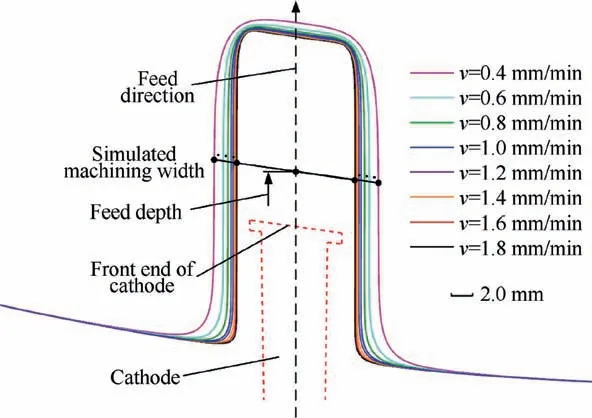
Fig.7 Prediction profiles of channel with different feed rates.

3.3.Obtainment of feed rates in each stage
According to the depth of a standard blisk channel,the process of the variable feed rate mode is divided into nine stages.Then,the values of the feed depth are obtained in each stage.
The ideal machining widths are measured in the desired profile of the machined blisk channel.Then,the values of the ideal side gaps corresponding to the different feed depths are obtained using Eq.(9).
In each stage,the value of the corresponding feed rate can be obtained by substituting the feed depth and ideal side gap value into Eq.(11).These data above are listed in Table 3.
Fig.9 shows the strategy for the variable feed rate,which can be developed by combining the feed rates in each row of Table 3.In Fig.9,the start-point coordinate of the x-axis is 4.5 mm;this is the starting position where the feed rate of cathode begins to dynamically change in the ECM process of the blisk channel.
4.Experiment and result
4.1.Experiment condition
The blisk channel ECM with a variable feed rate mode was employed experimentally to verify its feasibility and accuracy.
The experiments were conducted with a self-developed blisk ECM machine tool,as shown in Fig.10(a).The ECM fixture,workpiece,and cathode are displayed in Fig.10(b),along with other main components of the process.The ECM fixture(made of epoxy materials)provided a sealed flow channel with the workpiece and cathode.There was one electrolyte inlet on the fixture top,and one outlet on the side.The workpiece material was Inconel 718.The cathode was made of stainless steel,and could move horizontally towards the workpiece during the ECM of the blisk channel.In the ECM process of the blisk channel,the feed rate of the B axis was dynamically adjusted by a numerical control system.Accordingly,the feed rate of the tool cathode was various.
Contrast experiments were conducted under various feed rates ranging from 0.48 to 1.38 mm/min,and at a constant feed rate of 1 mm/min.The other experimental conditions are listed in Table 4.
4.2.Experimental results and discussion
The current changes during the experiment are shown in Fig.11.For a constant feed rate,the current increases smoothly,and the machining process basically reaches an equi-librium state in the final stage.However,for a machining process with a variable feed rate,the current changes constantly.When the feed depth of the cathode is between 0 and 4.5 mm,the current increases smoothly,and the machining tends to balance gradually.When the cathode is fed to 4.5 mm,the feed rate changes from 1 mm/min to 0.48 mm/min,resulting in a sudden drop in current,which increases the machining gap and the width of the blisk channel.After the cathode is fed to 4.5 mm,the whole current increases progressively.When the cathode is fed to the final position,the current density reaches the maximum of 83 A/cm2.At this time,the machining gap is the smallest,and the width of the blisk channel is the narrowest.Based on the variable feed rate,the shape of the machined channel is narrow at the root of the blade and wide at the tip of the blade,which is as consistent with the standard blisk channel shape as possible.
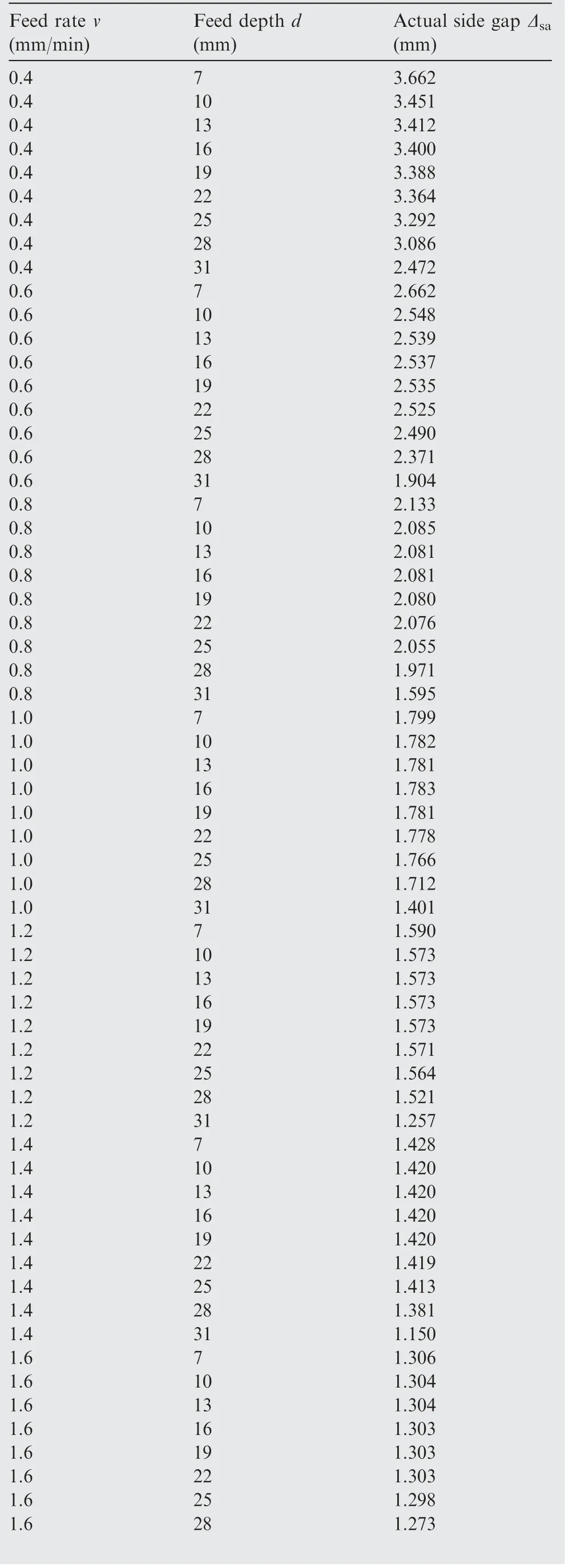
Table 2 Simulation data.
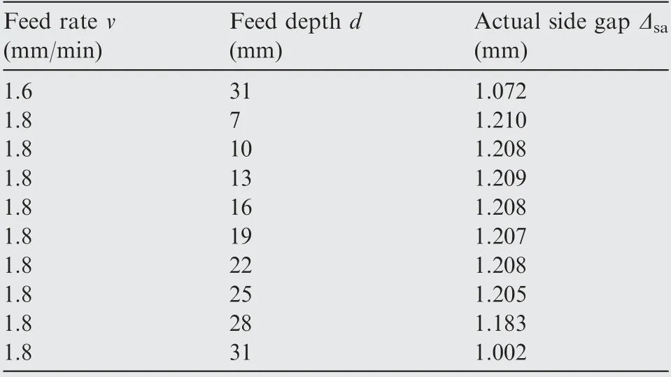
Table 2(continued)
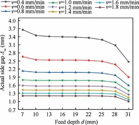
Fig.8 Variation of actual side gap with respect to the feed depth under different feed rates.
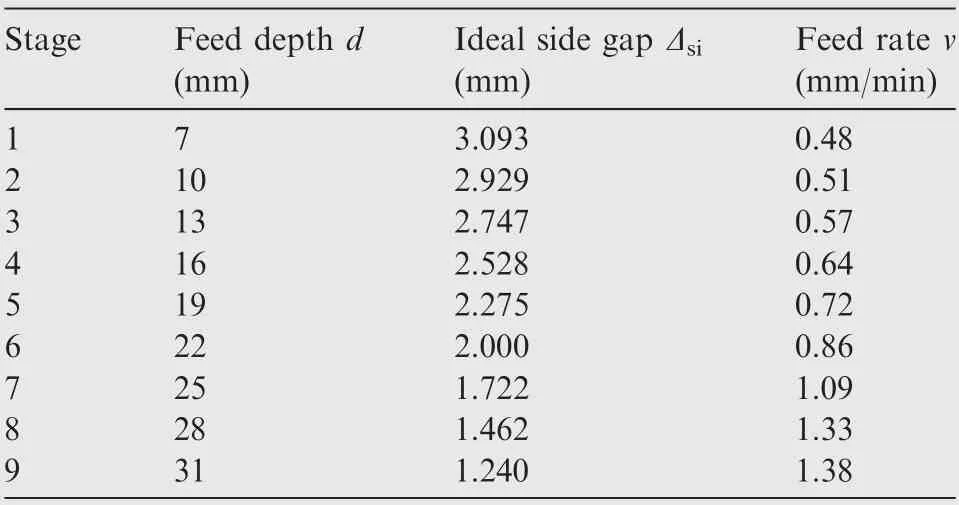
Table 3 Data regarding values of feed depth,ideal side gap,and feed rate.
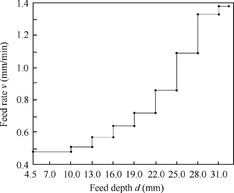
Fig.9 Optimization strategy for variable feed rate.
Fig.12 shows the channel machining sample(a)and the simulated channel profiles.The channel profile(b)is obtained using a constant feed rate,and the channel profile(c)is obtained using a variable feed rate.With the constant feed rate,the shape of the machined blisk channel is too simple to meet the requirements of the complex channel.In contrast,with the variable feed rate,the shape of the machined blisk channel is more twisted,and more in line with the shape of the standard blisk channel.
Fig.13 shows the allowance distributions of blisk channels machined by ECM with a constant feed rate and variable feed rate in section A,respectively,as measured by a coordinate measuring machine(TESA Micro-Hite 3D).The profile curves of the convex and concave parts of the blade are both discretised into 20 measuring points from the tip to the dotted line,as shown in Fig.14.
Table 5 lists the maximum and minimum values of the allowance and the allowance differences(in section A)for the blisk channels machined by ECM with a constant feed rate and variable feed rate,respectively.The allowance differences in the convex and concave parts for the blisk channel machined by ECM with a constant feed rate are 1.56 and 1.93 mm,respectively,whereas the corresponding values for the blisk channel machined by ECM with a variable feed rate are 0.59 and 0.63 mm,respectively.Compared with the allowance differences of the blisk channel machined using the constant feed rate,the allowance differences of the convex and concave parts machined using the variable feed rate are decreased by 62.2 % and 67.4 %,respectively.
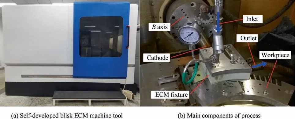
Fig.10 System image for blisk channel ECM with a variable feed rate mode.

Table 4 Experimental conditions.
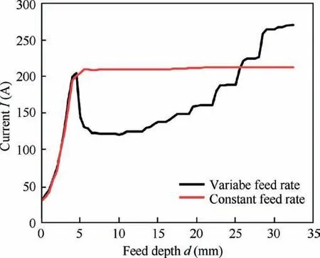
Fig.11 Change in current during machining process with a constant feed rate and variable feed rate.
In addition,a comparison of the experimental and simulated results is conducted.As shown in Fig.14(a),for the blisk channel based on ECM with a constant feed rate,the values of the allowance from experiment and simulation are compared at the same measuring point,and the average relative error is 8.37 %.As shown in Fig.14(b),the corresponding value for the blisk channel based on ECM with a variable feed rate is 9.93 %.The comparisons show that the simulated results basically coincide with the experimental results.The above experimental results and analyses show that the proposed method based on a variable feed rate mode is feasible and effective.
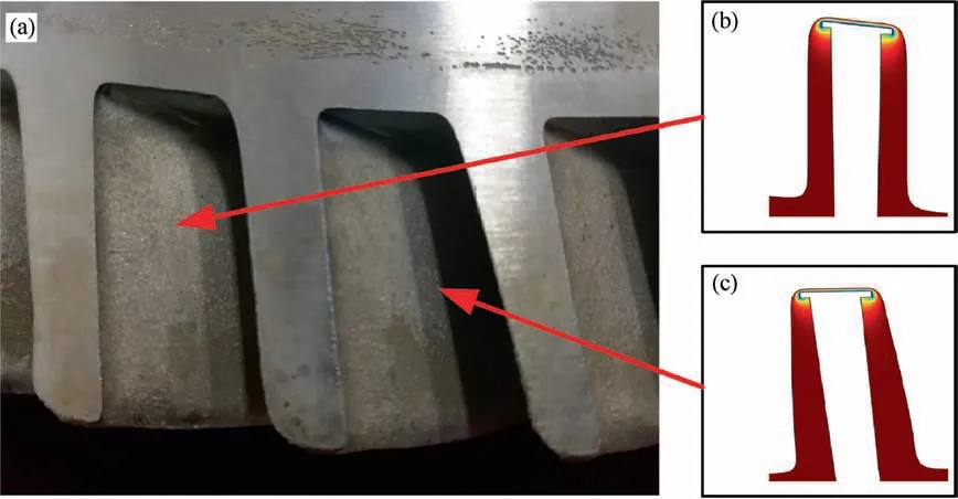
Fig.12 Comparison of different channels.
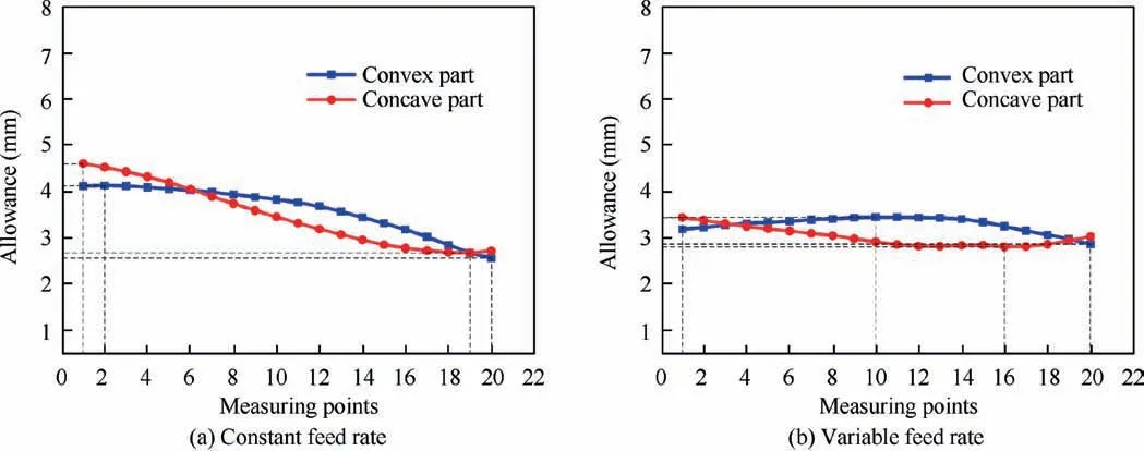
Fig.13 Allowance distributions of machined blisk channel.
The blisk channel with a radial feeding electrode has an advantage of good surface quality of hub.20Thus the surface roughness of the channel machining sample in the hub is measured using a roughness meter(Mar Perthometer M1).The values of Ra in hub for blisk channel ECM with a constant feed rate and variable feed rate are 0.204,0.161μm,respectively.The result shows that the surface roughness in the hub is decreased in the blisk channel ECM when using the variable feed rate.The reason is that the feed rate for the variable feed rate mode is higher than the constant feed rate mode in the final position,and the current density in machining gap is increased by increasing feed rate,and the surface roughness is decreased with an increase of current density.20
The machining times are also recorded for the blisk ECM with a constant feed rate and variable feed rate,and the values are about 32.40 and 45.40 min,respectively.The result shows that the machining time is increased in the blisk channel ECM when using the variable feed rate.However,the uniformity of allowance distribution in the blisk channel ECM is improved when using the variable feed rate,contributing to a decrease in machining time for the subsequent profile machining.Therefore,for the variable feed rate mode,the machining time for entire ECM process of the blisk is not actually increased.
5.Conclusions
A novel method,denoted the‘variable feed rate mode’,was applied for the ECM of blisk channels.The cathode was fed from the tip to the hub with various feed rates,for improving the allowance uniformity of the machined blisk channel.The effects of the blisk channel ECM with the variable feed rate mode were investigated via simulations and contrast experiments.The following conclusions can be drawn regarding the variable feed rate mode.
(1)Based on a theoretical analysis,the traditional constant feed rate mode cannot maintain the uniformity of an allowance after a channel is machined.With the variable feed rate mode,the size of the side gap can be adjusted,thereby changing the channel machining width and improving the uniformity of the allowance.
(2)Based on the simulation results,the relationship among the feed rate,feed depth,and side gap is obtained as a twodimensional polynomial equation.Different feed rates are achieved by varying the feed depth and side gap.Then,an optimization strategy for the variable feed rate can be achieved by combining the feed rates of different stages.
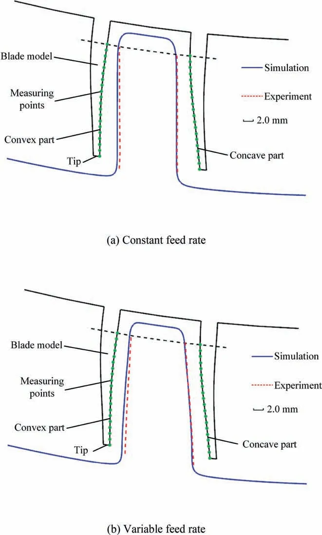
Fig.14 Comparison of experimental results and simulated results.
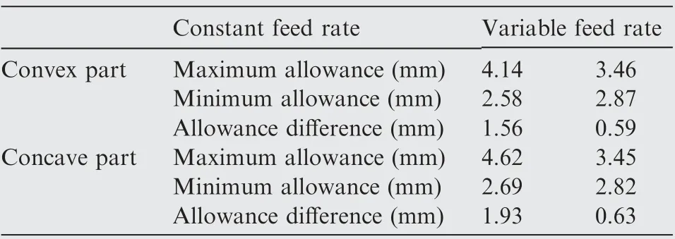
Table 5 Experimental data of allowance distributions.
(3)Twisted blisk channels are obtained experimentally,using the variable feed rate.As compared with those from a constant feed rate,the allowance differences in the convex and concave parts are decreased by 62.2 %and 67.4 % in the selected section,respectively.The results indicate that using the variable feed rate mode can effectively decrease the allowance differences in machined blisk channels.
Declaration of Competing Interest
The authors declare that they have no known competing financial interests or personal relationships that could have appeared to influence the work reported in this paper.
Acknowledgements
This work was supported by the National Science and Technology Major Project(No.2017-VII-0004-0097)and the Natural Science Foundation for Distinguished Young Scholars of Jiangsu Province(No.BK20170031).
 CHINESE JOURNAL OF AERONAUTICS2021年6期
- CHINESE JOURNAL OF AERONAUTICS的其它文章
- Performance evaluation of creep feed grinding ofγ-TiAl intermetallics with electroplated diamond wheels
- Thermomechanical coupling effect on characteristics of oxide film during ultrasonic vibration-assisted ELID grinding ZTA ceramics
- Modeling and experiment of grinding wheel axial profiles based on gear hobs
- Framework and development of data-driven physics based model with application in dimensional accuracy prediction in pocket milling
- Electrode design using revolving entity extraction for high-efficiency electric discharge machining of integral shrouded blisk
- Performance analysis and application on Ti-6Al-4V of micro-forging system
