Performance analysis and application on Ti-6Al-4V of micro-forging system
Yufei GUI,Qi LIU,Yun ZHU,Sulin CHEN,Bin SHEN
School of Mechanical Engineering,Shanghai Jiao Tong University,Shanghai 200240,China
KEYWORDS
Abstract Micro-forging(MF)is a novel surface modification technology which is capable of smoothening and strengthening the workpiece surface simultaneously.Based on analysis of the mechanism and energy conversion of micro-forging process,an electromagnetically driven microforging system is developed.To further grasp the kinetic characteristic of the equipment,a simulation model is established and its accuracy is verified.With the help of simulation and experimental results,we propose an input voltage optimization method,which drives the micro-forging head moving in a uniform and stable way.In this study,the influence of MF on surface integrity of Ti-6Al-4V(TC4)is firstly reported.Experimental results show that MF treatment reduces surface roughness(Ra)and increases micro-hardness by 48% and 11.8% at most,respectively.Besides,a compressive stress layer with an amplitude of-1000 MPa and a depth of 0.8 mm is observed.This study analyzes the performance and reveals the potential of micro-forging technology,which lays a solid foundation for expanding its application in TC4 surface modification.
1.Introduction
Due to the existence of cyclic mechanical,thermal,and mechanical-thermal coupling loading,aircraft components are facing a great challenge of fatigue failure,which results in permanent damage.To solve this problem,some highperformance metals such as titanium alloy(TC4,Ti6242)and nickel-based alloy(Inconel,Monel)have been utilized in the aviation industry.1-4On the other hand,a variety of anti-fatigue manufacturing technologies has been developed to improve the surface integrity of components without changing their dimensions.5Currently,many comparatively mature methods including shot peening,6deep rolling,7and laser shock peening8are widely applied in production.However,these methods more or less have some disadvantages which limit their application,for example,poor controllability of process,deterioration of surface roughness,shallow depth of hardening layer,and complicated mechanical structure.Micro-forging(MF)is a young surface modification technology(also called machine hammer peening or dengeling).During the micro-forging process,a high-hardness MF head moves in a reciprocating motion between the limit block and the workpiece surface.Then the plastic deformation of workpiece material occurs each time the head impacts the workpiece surface.As a result,reduced surface roughness,enhanced hardness,and a compressive residual stress field could be achieved.The MF device can be attached to any kind of machine tool or industrial robot;thus,the location and magnitude of the generated smoothening and strengthening effect can be exactly controlled and the production cycle time and cost can be greatly reduced.
In general,the micro-forging system is classified into three types according to the actuator system:pneumatically driven technology,electromagnetically driven technology and piezoelectrically driven technology.9These three micro-forging technologies allow forging with different frequency ranges(100-300 Hz,20-500 Hz and≈700 Hz)and impact forces.This paper focuses on the electromagnetic micro-forging system because it shows a wider frequency adjusting range and a uniform forging intensity on the treated area.10Similar to linear Voice Coil Motors,the system actuator operates on the principle of the Lorentz force equation.Bleicher,et al.10built a unidimensional Simulink model of the micro-forging actuator and found that the ram got most of its kinetic energy by the impact on the workpiece and the upper limit block.Trauth11pointed out that the MF head followed the input frequency with a small phase shift because of the magnetic induction effects.However,the forging head stroke several times onto the workpiece surface during one impulse.Most of the researchers pay close attention to surface modification effects of the microforging technology and have conducted a lot of experiments to investigate the influence of process parameters on the surface integrity.9,12As mentioned in literature,13the main pillars of the micro-forging technology are the reduction of surface roughness,the improvement of hardness and the induction of compressive residual stress.The surface property of treated-samples is an integration of these three effects,which highly depends on material properties and the settings of process parameters.Bleicher,et al.14found that the micro-forging method could significantly reduce the surface roughness of tool steel and the smoothing extent was greater for softer materials.Besides,they indicated that the surface hardness of tool steel was increased by 5% to 14% after micro-forging treatment.Lienert,et al.15,16studied the residual stress distribution of quenched and tempered 4140 steel induced by MF process.Experimental results showed that a wide range of compressive residual stress depth distributions could be generated,which varied from medium stress of about-600 MPa and low penetration depths like shot peening and large stress of-1200 MPa and penetration depths comparable to deep rolling.
As a novel and potential surface treatment technology,micro-forging has been successfully applied in a wide range of industrial scenarios,such as post-treatment of welded joints,tribological characteristics improvement of tools,surface finishing of large automobile molds and parts.9However,available studies pay less attention to the development and performance of the micro-forging equipment itself.The mechanism behind the reciprocating motion and the energy conversion during the MF process is still unclear.Besides,the workpiece materials studied in available researches include cast iron,stainless steel,tool steel,structural steel,17-19aluminum alloy(AA7050),20and nickel-based alloy(NI718).21The enhancing effect of the MF on the surface integrity of titanium alloy has not been studied.
In this study,we analyze the kinetic characteristics of the MF system and investigate the effect of MF processing on the surface integrity of TC4 titanium alloy.We have developed a piece of micro-forging equipment and analyzed its dynamic behavior.Based on the kinetic characteristic of the developed MF device,we propose a selection strategy of optimal input voltage,which could generate a stable MF motion on the workpiece surface.Then,we examine the effectiveness of the MF processing on the surface integrity of a polished titanium alloy(TC4)workpiece.
2.Equipment development
2.1.Mechanism of micro-forging
The mechanism of the micro-forging technology lies in the uneven plastic flow of near-surface materials generated by mechanical impacts of the MF head.Hence surface unevenness is reduced and compressive residual stress is induced.There are two forces in the contact area,the normal force and the tangential force.5These two forces would lead to different plastic deformation degrees of metal materials in different directions.Generally,these two mechanisms take effect at the same time and the dominant strengthening mechanism changes with the difference between the hardness of the tool and workpiece.Because of the inevitable friction between the contact pair,the temperature in the contact area would rise,which also affects the hardness and stress distribution of treated materials.
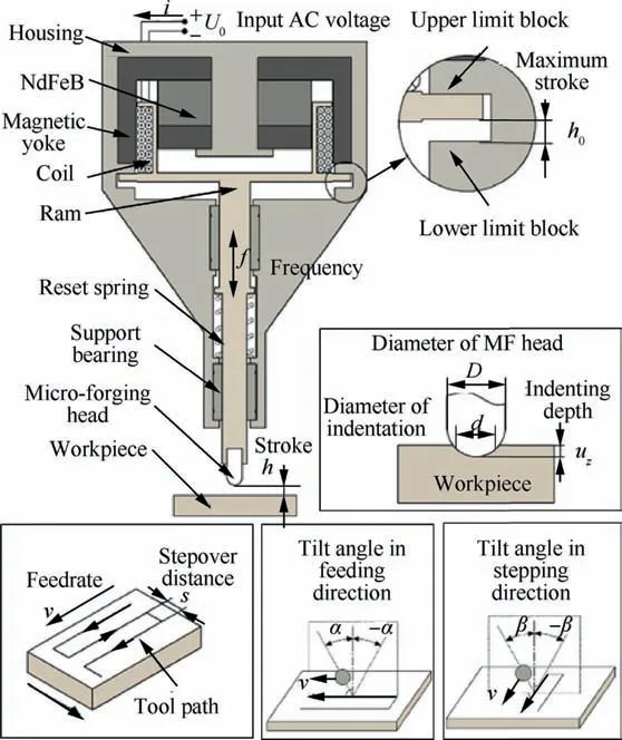
Fig.1 Structure of electromagnetically driven micro-forging equipment(boldface:process parameter).
Fig.1 demonstrates the typical structure of an electromagnetic micro-forging device.A permanent magnet and a yoke are installed in a metal housing and form a radial magnetic field with uniform intensity.A current-carrying conductor is placed in this magnetic field.Once the coil is energized,the ram will have an Ampere force along the axis exerted upon it.The direction of the force depends on the polarity of input current and the amount of force is proportional to the magnitude of the input current.Thereby the ram moves back and forth along the axial direction and the movement frequency f is highly related to the frequency of the input alternating current(AC).A high-hardness hemispherical tool head is fixed at the end of the ram.Various diameters D are provided to meet different surface modification requirements.The return spring ensures the moving mass stays in the initial position when the system is not working.The distance between the end of the tool head and the workpiece surface is defined as stroke h.The maximum stroke is h0,which is around equal to the distance between upper and lower limit blocks.According to Hertz’s contact theory,the contact area is similar to a circular area with a diameter of d and an indenting depth of uz.The size of the indentation is mainly affected by impact force FIand tool head diameter D.Furthermore,FIis closely related to input AC voltage U0,movement frequency f and stroke h.Therefore,the surface morphology and stress distribution generated during one single impact process can be exactly controlled through adjusting these parameters.As mentioned above,the micro-forging device usually serves as an operator installed on the end of a machine tool or an industrial robot and moves along the pre-planned path.The distance the tool head travels per unit time is defined as feedrate v and the distance between adjacent feeding paths is stepover distance s.These two parameters determine the distance between adjacent indentations,which further determine the surface morphology.Besides,the impact movement can be realized at a certain angle between the workpiece surface normal in the contact point and axis of the ram.When the ram axis is in the‘‘feed-surface normal plane”or perpendicular to feeding direction,the angle is denoted asαorβ.
Considering the periodicity of the ram’s movement,we focus on its kinetic characteristic during one movement period.This period is divided into four phases:descending-impacting on the workpiece-ascending-impacting on the upper limit block,as shown in Fig.2.From the perspective of energy conversion,gravity FGand spring force FSare conservative forces,thus their work is equal to the change of potential energy,which is zero because the initial position of the ram is the final one.Due to the existence of plastic deformation of the workpiece and the upper limit block materials,both impact forces FIand Fuswould do negative work and consume kinetic energy of the ram.The Ampere force FAis the source of the kinetic energy of the ram,which ideally do positive work all the time to maintain the stability of the system.Besides,the work caused by the friction Ffbetween mechanical components is converted into heat and reduces a part of system energy.Based on the above analysis,the micro-forging process is essentially a process of energy conversion from the work produced by the Ampere force,or kinetic energy of the ram into plastic deformation energy of metal materials and thermal energy.In terms of the duration of each phase,the descending and ascending phases take most of the whole period while the other two impacting phases can be regarded as an instantaneous process.Thus,the amplitude of FIand Fusis supposed to reach a very high level to generate a high enough acceleration and instantly reverse the velocity direction of the ram.
2.2.Equipment design
Based on the mechanism of the MF process,an electromagnetic micro-forging system is designed and assembled as shown in Fig.3.A permanent magnet made of NdFeB and a yoke composed of stacked silicon steel sheets were installed on the top of the housing.The grade of the magnet is N42 with a residual magnetization of 12.9 T.The intensity of the magnetic field is uniform within the maximum stroke h0=2 mm.The return spring provides a preload of 40 N.The micro-forging head is made of high-hardness and high-wear-resistant tungsten carbide material.The tool head has three kinds of diameters of 5 mm,7 mm and 12 mm.Large current flow through the coil generates high temperature,which might damage the stability of the magnetic field.Therefore,we integrate a cooling system into the equipment.
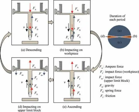
Fig.2 Force condition of ram during single movement period.
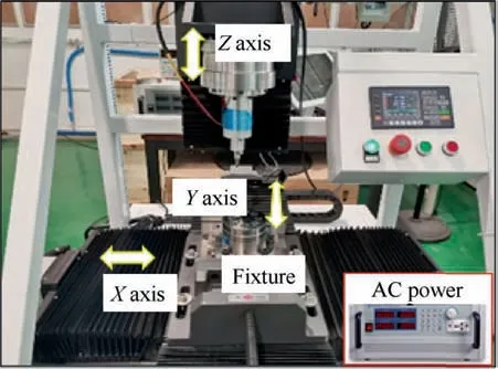
Fig.3 Electromagnetic micro-forging system.
The micro-forging system is based on a frame-structure motion platform with three degrees of freedom.The maximum stroke in X/Y/Z direction is 470 mm,320 mm,230 mm,respectively.The servo motor has a positioning precision of±0.02 mm and allowance load of 6 kN.The fixture is mounted on the horizon table and the MF equipment is installed on the Z-axis.A programmable AC frequencyscaling power supplies the sine-wave voltage.The range and frequency of the output voltage are 0-300 VAC and 45-500 Hz,respectively.
3.Performance analysis
3.1.Dynamic model
To analyze the motion of the ram,a unidimensional model was built in Simulink(Fig.4).Based on Newton’s laws of motion,the dynamic equation is expressed as:

where m is the mass of the ram,FGis the gravity,FAis the Ampere force,Fusand Flsdenote the impact forces provided by the upper and lower limit block,respectively,Ffis the internal mechanical friction,FSis the spring force,and FIrepresents the impact force coming from the workpiece.The dynamic characteristic of the upper limit block is considered as a spring-damper-system:

where kusdenotes the elastic stiffness and cusdenote the system damping,which is used to describe the speed loss of the ram due to vibration and friction in the contact area with the upper limit block.
The Johnson-Cook model is utilized to calculate the stressstrain property of TC4 material.The influence of strain,strain rate and temperature on the dynamic mechanical characteristic of the material can be expressed as:

whereσJCdenotes Von Mises flow stress and A,B,n,C,m are parameters related to material performance,εis the equivalent plastic strain,˙εand˙ε0are the equivalent plastic strain rate and the reference strain rate,respectively,Tmis the melting point of the material and Tris the reference temperature.
3.2.Model validation
To validate the accuracy of the dynamic model,the impact tests are conducted.A Keyence LK-H008 laser displacement sensor is utilized to measure the displacement of the microforging head.The measurement range of this sensor is±0.5 mm and the repositioning resolution is 0.005μm.The sampling frequency is set to 10000 Hz.The MF process parameters are set as follows:head diameter D=12 mm,stroke h=0.3 mm,input AC voltage U0=9 V,AC frequency f=50 Hz,feedrate v and stepover s are both equal to 0 mm/min.
Two displacement curves obtained via simulation and experiment are displayed in Fig.5.The movement frequency of the ram is 50 Hz,which indicates that the reciprocating motion of the head can be controlled through adjusting the input alternating current.The fact that there is no obvious shift between the two curves both in the time axis and displacement axis proves that the dynamic model can provide an accurate prediction on the motion of the ram.The correlation coefficient between these two displacement curves reaches 0.962.
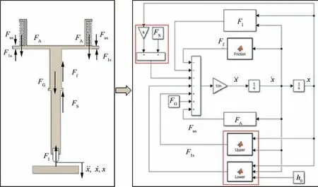
Fig.4 Unidimensional Simulink model of MF system.
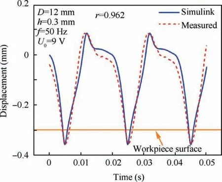
Fig.5 Comparison between simulation and experimental displacement curves.
3.3.Kinetic characteristic
The above analysis illustrates that the Ampere force FAhas a significant influence on the reciprocating motion of the ram.If the driven force drops to a low level,the micro-forging head cannot even obtain enough kinetic energy to hit the workpiece surface.This force is proportional to the magnitude of the current passing through the coil and the flux density field.Since the permanent magnet flux density field is fixed and uniform within the maximum stroke of the coil,it is necessary to find an appropriate input AC voltage to keep the ram moving stably between the upper limit block and the workpiece.
Firstly,the correlation between the input voltage and the motion pattern of the ram is investigated in the Simulink environment.The MF head with a diameter in 12 mm is used.The stroke h and frequency f are 0.3 mm and 50 Hz,respectively.The feedrate v and the stepover s are both zero.The experimental variable is the effective value of the AC voltage U0,which is changing among 3/6/9/12/16 V.The displacement,velocity,and Ampere force curves are used to observe the kinetic characteristic of the ram,as shown in Fig.6.
In Fig.6(a),(b)and(d),the ram always enters the stable moving stage after a short adjustment process.It illustrates that there exists a self-adjusting process within the system which ensures a reproducible movement of the ram at a constant frequency.It can be seen that the higher the input voltage is,the shorter the adjusting process needs.Hence,the high input voltage brings the MF system a better dynamic response characteristic.The mechanism of this phenomenon is the dynamic equilibrium between the current in the closed coil and the velocity of the ram.The Ampere force increases with the increase of the input AC,which leads to an increment in the velocity of the ram.Meanwhile,the movement of the conductor placed in the magnetic field will result in the generation of motional electromotive force,which is directly proportional to the magnitude of the velocity and helps slow the rate of speed increasing.In Fig.6(c),as the movement direction reverses during impacting on the workpiece stage,the direction of the motional current in the coil is in accord with the input AC at this moment,which delays the decrease of the Ampere force.This phenomenon reveals that the essence of the selfadaptive adjustment is adjusting the phase difference between the movement of the ram and the input AC.
In Fig.6(a),the micro-forging head does not reach the workpiece surface under the input AC voltage of 3 V.Driven by an AC voltage of 9 V,the ram moves more smoothly and the indenting depth during each motion cycle is almost a constant value of 0.05 mm,as demonstrated in Fig.6(b).When the input voltage reaches 16 V,the head impacts on the workpiece twice in one motion cycle because of the excessive magnitude of the Ampere force.We describe this phenomenon as a‘‘secondary impact”.The intensities of two successive impacts are not the same,bringing uncertainty to the control of the MFtreated surface morphology.Thus,the‘‘secondary impact”should be avoided in practical application.
Fig.6(e)displays the displacement curve and Ampere force curve of the ram with the input voltage U0of 6 V,9 V and 12 V.Similar to the moving pattern driven by the U0of 9 V,the voltages of 6 V and 12 V could also push the ram back and forth in a smooth way and the‘‘secondary impact”phenomenon does not occur.Thus,the voltages of 6 V and 12 V can be regarded as ideal input voltages,too.The simulation result indicates that as long as the input voltage is within a reasonable range the ram is able to move stably.With the increase of the voltage,the Ampere force and the indenting depth both increase and the phase difference between the motion of the ram and the input AC decreases.
Fig.6(f)gives an example of the ideal input voltage range calculated using Simulink.As seen from the figure,a high input voltage is needed to generate a high-frequency movement.However,the maximum electric current in the cooper coil is 8 A.Thus,the maximum input voltage is codetermined by the motion pattern of the ram and the property of the coil.Moreover,the minimum and the maximum input voltage curves intersect at the frequency of 160 Hz,which indicates the maximum continuous working frequency of the system is 160 Hz.It should be noted that the simulation result just provides a roughly ideal input voltage range because the dynamic model does not consider the influence of thermal effect on the magnetic field intensity.Thus,more experiments should be carried out to determine the optimal input voltage corresponding to different parameters including the micro-forging head diameter,the stroke and the frequency.
3.4.Input voltage optimization
The optimal input AC voltage is investigated through a series of full-factor impact experiments.The displacement of the micro-forging head is captured by the Keyence LK-H008 laser displacement sensor.Table 1 shows the experimental variables and value ranges.According to the simulation result,there exists a specific range of the input voltage corresponding to a fixed set of process parameters D,h and f,as shown in Fig.6(f).The value of U0increases by a certain amount within this reasonable range every three seconds in one experimental group and the total number of experimental groups is 60.
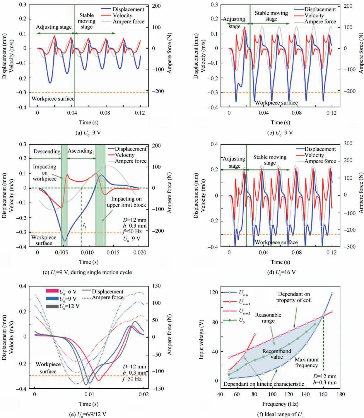
Fig.6 Displacement,velocity and Ampere force curves of the ram and ideal range of input voltage.

Table 1 Experimental variables and value ranges.
This paper takes one set of experiment with D of 5 mm,h of 0.1 mm and f of 50 Hz as an example to illustrate the optimization procedure of the input voltage.Fig.7(a)shows the maximum displacements of the ram under different input voltages.The ram does not reach the workpiece surface until the input voltage grows to 4 V.To obtain more information about the motion pattern,the movements of the ram within several moving periods are extracted as shown in Fig.7(b)-(f).In Fig.7(b),the maximum displacement of the MF head is 0.05 mm,which means the contact does not happen.The situation changes when the input voltage increases to 4 V.Although the movement of the ram remains frequency with an approximate value of 50 Hz,the maximum displacements in two successive moving cycles are not consistent.The impact on the workpiece surface occurs every 0.04 s,which indicates the kinetic energy of the ram cumulating in two motion cycles is sufficient to induce plastic deformation of the workpiece material.Fig.7(d)and(e)demonstrate that both the input voltage of 5 V and 8 V could drive the ram back and forth stably.However,the moving mass generates a deeper indentation in the latter case and does not rise again after impacting on the upper limit block,which is more efficient.Besides,the‘‘secondary impact”phenomenon appears as the input voltage grows to 10 V.Therefore,8 V is selected as the optimal input AC voltage for the combination of D=5 mm,h=0.1 mm,and f=50 Hz.
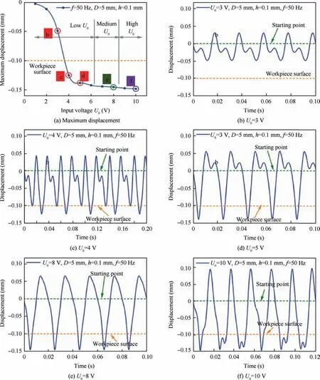
Fig.7 Displacement curves of ram.
Fig.8 displays the optimal input voltages selected via the above procedure.It can be found that the optimal input voltage increases with the stroke and frequency,while the difference of the head diameter does not result in significant diversity of this voltage.Thus,the influence of MF head diameter on input voltages is ignored and the final results are displayed in Table 2.It is possible to realize a stable,uniform,and continuous impact movement using the experimental parameter in this table.
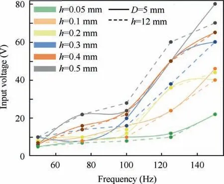
Fig.8 Optimal input voltages corresponding to specific sets of process parameters.

Table 2 Optimal input voltages.
4.Experimental
4.1.Experimental setup
The effect of micro-forging treatment on the TC4 titanium alloy has been investigated.The experimental design is shown in Table 3.The size of the micro-forging region is 40 mm×100 mm.The feedrate and stepover are set to small values so that the overlapping ratio is as high as possible.The experimental material is hot-rolled TC4 plates with a thickness of 3 mm.The original surface has been treated using manual polishing and thus its roughness is as low as Ra~70 nm.The surface integrity of the samples is described by surface morphology,roughness,micro-hardness,and residual stress field,which are measured via ZEISS Smartproof 5 confocal microscope,HXD-1000TM/LCD digital micro-hardness tester and Pulstecμ-X360s portable X-ray residual stress analyzer,respectively.Considering the limited penetrating depth of Xray,the sample is stripped by the chemical corrosion and then the residual stress is measured layer by layer.
4.2.Experimental results
Fig.9 displays the surface morphology of original and experimental samples.The polished surface(Fig.9(a))has a roughness of Ra=0.07μm and Sa=0.51μm without obvious machined traces.Due to the plastic deformation of the metal material,several parallel linear indentations appear on the experimental sample 1 surface.The 3D morphology in Fig.9(b)clearly shows the feed paths of the micro-forging treatment.The distance between adjacent indentations on experimental sample 2(Fig.9(c))becomes much closer.This result illustrates that micro-forging with a small overlapping ratio could produce a smooth and homogeneous surface on TC4 workpiece.As displayed in Fig.9(d),the indenting depth on the surface is very shallow and visible uneven areas do not exist.The surface roughness Rahas been reduced to 0.04μm,which means the MF treated surface even smoother than the original finished surface.
The changes of surface integrity are evaluated through three indices as listed in Fig.10.Firstly,the surface roughness decreases in experiment 2 and 3.Given that the roughness of the original surface has already reached an extremely low level,the result that the surface is smoothened after micro-forging treatment strongly illustrates that this technology has a great potential to reduce surface roughness.Fig.10(b)shows that MF processing can result in a remarkable work hardening effect on TC4 workpiece.The degree of micro-hardness improvement highly depends on process parameters.Experimental results also reveal that the micro-forging method is capable of inducing a high residual compressive stress field inside the workpiece.Residual tensile stress appears on the polished workpiece surface,as shown in Fig.10(c).On the surface of experiment sample 1 and 2,the magnitude of residual stress increases to about-400 MPa and-1000 MPa in the feeding and stepping direction,respectively.The depth of the compressive stress layer reaches 0.8 mm at most.Besides,the residual stress in the stepping direction is higher than that in the feeding direction because of greater material plastic flow in the stepping direction.However,the depths where compressive stress changes to tensile stress in both two directions are the same.It means that the plastic deformation in different directions trends towards uniform with depth increasing.On the other hand,a much smaller and shallower compressive stress layer is generated on the surface of sample 3 since the impact energy is very low.
5.Discussion
In this paper,we demonstrate the structure,kinetic characteristic and application of an electromagnetic micro-forging system.The Ampere force serves as the energy source of reciprocating motion of the ram.During the impact between the MF head and the workpiece,a majority of the kinetic energy is converted into the plastic deformation energy of the material.Through the dynamic simulation and experimental result,we find that the input AC voltage makes a great dif-ference to the motion pattern of the ram.The existence of the Ampere force and motional electromotive force results in a self-adjusting process,which indicates that the whole system would finally enter a stable moving stage.In the stable moving phase,the movement frequency of the ram is the same as the AC frequency.Besides,the MF head cannot reach the workpiece surface under too low voltage,while the‘‘secondary impact”phenomenon occurs if the input AC voltage is set too high.We have determined the optimal value of this voltage corresponding to certain combinations of the stroke and frequency.These two parameters are primary factors that affect the velocity of the moving mass,which essentially reflects the level of the impact energy.Thus,the stable and uniform impacting movement of the ram under the optimal input voltage ensures good controllability of the location and intensity of the micro-forging treatment.

Table 3 Experimental design.
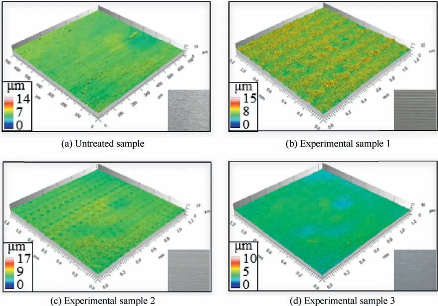
Fig.9 Surface morphology.
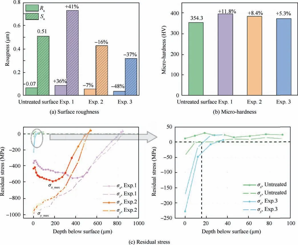
Fig.10 Changes of surface integrity.
Experimental results prove that micro-forging technology can effectively improve the surface integrity of TC4 workpiece,including good surface smoothening and strengthening performance.The fact that the residual stress in the stepping direction is higher than that in the feeding direction indicates more drastic dislocation inside the material in the stepping direction.Thus,the micro-forging method can specifically improve the fatigue strength of components subjected to uniaxial alternate loading.It is worth noting that the setting of process parameters has a great influence on the plastic deformation of the material.For example,using the parameter values in experiment 1,the best hardening and strengthening effect can be obtained,but the surface roughness is slightly increased.On the contrary,the MF-treated sample in experiment 3 shows a highly finishing surface,but the small and shallow residual compressive stress field inside the material suggests that the fatigue resistance performance of this workpiece is almost not improved.In experimental 2,the effect of the micro-forging treatment achieves a balance between surface smoothening and strengthening.Therefore,it is necessary to further optimize process parameter settings to obtain the desired surface integrity of high-performance components.
The performance analysis of an electromagnetic MF system provides a reference for optimizing the structure design and the surface modification effect on TC4 samples demonstrates promising applications of the MF technology,especially in the aviation industry.Although the surface integrity of experimental samples is impressively enhanced after MF treatment,the allowable maximum movement frequency of this microforging device is about 160 Hz,which is less than the maximum frequency of general electromagnetically driven MF equipment(500 Hz).9,12In the future,the structure of the device should be further improved and various sensing modules,such as the displacement sensor,force sensor and temperature sensor would be integrated into the device so that a more controllable and intelligent micro-forging system could be developed.Meanwhile,we will investigate the fatigue strength of MF-treated TC4 components to support the application of this new technology.
6.Conclusion
This paper introduces a novel type of surface modification treatment technology,micro-forging.An electromagnetic MF device is developed and its kinetic characteristic is analyzed using Simulink.Then the optimization strategy of the input AC voltage is proposed to generate a uniform and controllable movement of the ram.Finally,micro-forging treatment on TC4 titanium alloy workpiece is introduced and the experimental results demonstrate its satisfactory surface smoothening and strengthening effects.After MF treatment,the TC4 sample has the minimum roughness Raof 0.04μm,the maximum surface micro-hardness of 396.2 HV,and the maximum residual compressive stress of-1000 MPa with the depth of compressive stress layer of 0.8 mm.The work reported in this paper lays a solid foundation for future research on the surface modification mechanism of TC4 components using microforging technology.
Declaration of Competing Interest
The authors declare that they have no known competing financial interests or personal relationships that could have appeared to influence the work reported in this paper.
Acknowledgements
This study was co-supported by the National Major Science and Technology Projects of China(No.2018ZX04005001-002),State Administration for Science,Technology and Industry for National Defense of China(No.DE0904)and Shanghai Academy of Spaceflight Technology of China(No.SAST2018-055).
 CHINESE JOURNAL OF AERONAUTICS2021年6期
- CHINESE JOURNAL OF AERONAUTICS的其它文章
- Performance evaluation of creep feed grinding ofγ-TiAl intermetallics with electroplated diamond wheels
- Thermomechanical coupling effect on characteristics of oxide film during ultrasonic vibration-assisted ELID grinding ZTA ceramics
- Modeling and experiment of grinding wheel axial profiles based on gear hobs
- Electrochemical machining on blisk channels with a variable feed rate mode
- Framework and development of data-driven physics based model with application in dimensional accuracy prediction in pocket milling
- Electrode design using revolving entity extraction for high-efficiency electric discharge machining of integral shrouded blisk
