Vibrations characterization in milling of low stiffness parts with a rubber-based vacuum fixture
Antonio RUBIO-MATEOS,Mikel CASUSO,Asuncion RIVERO,Eneko UKAR,Aitzol LAMIKIZ
a TECNALIA,Basque Research and Technology Alliance(BRTA),Paseo Mikeletegi 7,Parque Tecnolo´gico,E-20009 San Sebastian,Spain
b University of the Basque Country(UPV/EHU),ETTSII-Department of Mechanical Engineering,C/Alameda de Urquijo s/n,E-48013 Bilbao,Spain
KEYWORDS
Abstract Fixtures are a critical element in machining operations as they are the interface between the part and the machine.These components are responsible for the precise part location on the machine table and for the proper dynamic stability maintenance during the manufacturing operations.Although these two features are deeply related,they are usually studied separately.On the one hand,diverse adaptable solutions have been developed for the clamping of different variable geometries.Parallelly,the stability of the part has been long studied to reduce the forced vibration and the chatter effects,especially on thin parts machining operations typically performed in the aeronautic field,such as the skin panels milling.The present work proposes a commitment between both features by the presentation of an innovative vacuum fixture based on the use of a vulcanized rubber layer.This solution presents high flexibility as it can be adapted to different geometries while providing a proper damping capacity due to the viscoelastic and elastoplastic behaviour of these compounds.Moreover,the sealing properties of these elastomers provide the perfect combination to transform a rubber layer into a flexible vacuum table.Therefore,in order to validate the suitability of this fixture,a test bench is manufactured and tested under uniaxial compression loads and under real finish milling conditions over AA2024 part samples.Finally,a roughness model is proposed and analysed in order to characterize the part vibration sources.
1.Introduction
The search for flexible clamping solutions has been a prior task over the last decades,1,2as the fixturing process is a critical factor with influence on the machining accuracy of high-precision parts.3Among the different machining cases,the floor-milling process of thin parts is one of the most critical operation due to the thickness and roughness quality tolerances required in the industry.These low stiffness aluminum parts,as aeronautic skin panels,are milled to reduce the aircraft weight and cost.4
Traditionally,this sort of parts has been chemically milled.However,this non-conventional process has low efficiency and causes pollution issues.Thus,it leads to employ more efficient and competitive technologies.
Nowadays,the simplest flat skins are manufactured on vacuum tables.These fixtures position the workpieces onto the machine bed and provide proper clamping conditions to implement heavy cutting operations.5Nevertheless,these fixed solutions are limited to certain geometries and references.The rest of the parts are only feasible through a high cost redesign or a brand-new fixture manufacturing.
For the machining and assembling of certain low stiffness parts there are diverse reconfigurable pin-array fixtures.2However,these solutions lack the accuracy or the stiffness to guarantee the part acceptance criteria.6For instance,in order to increase the stiffness of the part support,Youcef-Toumi and Buitrago7proposed a conformable fixture with a superelastic NiTi alloy.Nevertheless,these adaptable elements can only be employed as a support,not a clamping surface.Thus,as an alternative for the existing solutions,other technically complex developments have been developed.The most extended system is the so-called Greenhouse technology.8This system combines an outer clamping system and two synchronizes machine heads moving at each side of the panel.Therefore,as the tool is milling,the mirror system provides support to prevent the part deflection,and,thus,the thickness tolerance is guaranteed.This solution has already reached the industry9,10but its implementation is limited due to the high investment required.The only alternative development to reduce the investment cost as the clamping flexibility is maintained is the magnetic end effector proposed by Mahmud et al.11This solution substitutes the second machine head by a grasping device magnetically attached to the tool head.However,the element that provides displacement by rolling over the opposite side of the part marks the skin due to the dirt derived from the machining process.
On the other hand,despite a proper clamping device,vibration problems appear.Part vibration on milling operations is a long-studied phenomenon that concern all the manufacturing industry.Both,chatter12and forced vibrations13have been deeply analysed.Different vibration analysis have been focused on the tool-part system characterization,14,15on the tuning of machining process parameters,16on the implementation of active features17-19and on the passive damping elements integration.20,21Nevertheless,these developments are focused in the process stability rather than in the system flexibility for the clamping of diverse part references.
In the present study,an alternative fixture,based on a flexible clamping solution with high damping capacity,is proposed.This solution is developed with an adapted rubber plate.These elastomers are ideal materials as vibration isolators as they are low in cost with high internal friction.22For instance,Craig et al.23propose conformable fixture systems with flexure pins for improved workpiece damping.However,these solutions are based in the part containment from both sides.On the other hand,Li et al.24present an elastic mechanics-based fixturing for the face milling of variable stiffness structure.Nevertheless,this pin-array solution is employed for the machining process of high stiffness parts and it is not adaptable for complex geometries.
The proposed solution combines the damping capacity of the rubbers with the outstanding sealing properties of the nitrile butadiene rubber(NBR)25-27to transform a flexible plate into a adaptable vacuum table.Thus,the process vibrations are mitigated,and the part clamping can be made uniformly by the opposite side of the machined zone.Moreover,due to the outstanding vacuum isolation capacity,this sort of fixtures has the capacity to clamp different part references without any redesign.This solution,despite their wide thickness tolerances,could be employed in aeronautical applications by means of adaptable supports combined with part position and thickness monitoring technologies.28In order to characterize the behaviour of this concept,compression tests and milling tests have been performed based on aeronautic references.Thus,the effect of the test sample material loss and stiffness combined with the tool cutting conditions are analysed in terms of the floor surface quality.Finally,a roughness model is proposed to identify and characterize the process vibration sources responsible for the roughness increase.
2.Experimental plan and set up
Two different NBR compounds are selected as part supporting elements.The first one is a NBR65 layer with a 65±5 Sh A,a 1.45 g/cm3density and a working temperature range between-10°C and 70°C.The second analysed material is a harder equivalent NBR compound.This NBR90 has 90 Sh A hardness,a 1.43 g/cm3density and a working temperature range between-30°Cand120°C.Bothlayersare 300 mm×300 mm wide and 14.2±0.7 mm thick.
Vulcanized rubbers have different behaviours based on the characteristics of the applied loads.Thus,the amplitude,feed rate and frequency of the forces,together with the temperature of the material define their strain rate.29In the milling case,the amplitude and the feed rate of the load is mainly defined by the machining conditions.Moreover,the frequency of the load over the fixture is generated by the milling tool rotation and by the workpiece fundamental modes.However,as studied by Kolluru and Axinte,30in milling thin parts,the resonant vibration generated by the tool become dominant over the workpiece fundamental modes as the stock of removed material increases.Finally,the temperature of the material is influenced by the heat generated on the cutting zone and by the room temperature.
Machining strategies employed in the aeronautic industry can lead to different simplifications.For instance,based on the toolpaths employed on the of skin panels manufacturing,the optimum milling strategy is the outward helicoidal toolpath.4Thus,the influence of each tool step over each fixture zone can be considered so time-separated that compressive and thermal accumulative effects could be ignored.Thus,the material strain is considered completely recovered between consecutive tool steps and the elastomer temperature is limited to the room value.Finally,the stiffness decrease during the first few cyclic loads,the so-called Mullins effect,31is not considered as different compression loads prior to the survey are performed.
Each proposed flexible layer is adapted into a vacuum fixture.A channel grid is machined along the elastic piece.A unique hole connected to the channels is included to extract the air from the channels and perform a suitable vacuum clamping to the part.The channels have 5 mm×5 mm sections and the evacuating orifice is∅8 mm.
All the tests are performed in a standard 5-axis NC centre and the machined material is the aluminum alloy 2024-T3 widely employed in the aeronautic industry.The milling operations are performed with a two flutes bull-nose end-mill Kendu 4400,with a diameter of 10 mm and a 2.5 mm edge radius(r).The forces are monitored with a Kistler 9257B table.The thickness distributions of the part samples are evaluated with an Olympus Panametrics-NDT 35DL ultrasonic probe.On the other hand,the average roughness(Ra)of the floors are measured with a Mitutoyo Surftest SV-2000 roughness measure station.
In order to guarantee chatter-free machining conditions,the axial frequency response functions(FRFs)of each part sample is complemented with the FRFs of the tool in order to calculate the stability lobe diagram(SLD)of each system.An impact hammer and uniaxial PCB accelerometer model 352C22 with a measuring range from 1 to 10 kHz and a sensitivity of 1.0 mV/(m/s2)is employed.Then,the maximum acceptable depth of cut(ap)in stable regime is calculated with the procedure described by Altintas and Budak.32
In order to analyse the effect of the hardness of each rubber and the part stiffness loss in the machining quality three complementary surveys are performed.The employed working parameters are defined within the values presented in the Table 1,where fzis the feed per tooth,S spindle speed,Vcthe cutting speed,f the feed rate and h the machined part thickness.
2.1.Compression tests
The first test bench is designed for the performance of compression tests to determine similar rheological behaviour on both compounds considering the feed rate effect.In general,compression tests on rubber materials are performed with circular samples.33However,in order to include the effect of the channels in the material deformation the tests are implemented directly in the same fixture employed throughout the survey,as shown in the Fig.1.
The loads are applied in the middle of the elastic layer by means of a cylindrical punch driven by the machine head and monitored with a GT1000 type LVDT gauging transducer.Likewise other similar set-up,34the part and the elastic element are stuck to the force sensor using a synthetic rubber adhesive.This double-sided filmic tape CESA 64,620 guarantee a homogeneous clamping.
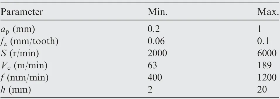
Table 1 Working range.
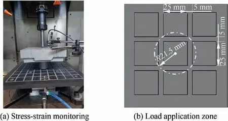
Fig.1 Compression test set up.
Three equidistant feed rates from the working range are tested.Besides,three repetitions are performed for each condition and,in order to avoid compressive accumulative effects,only the third trial is analysed.
2.2.Pocketing tests
These tests aim to analyse the effect of material loss in the machining process over the flexible fixtures.Due to the high profile variability of the rubbers compared with the thickness of low stiffness parts,different reduced pocketing tests are performed,as shown in the Fig.2.Hence,the previous set-up is complemented with a venturi to create a proper clamping conditions between the elastic layer and the low stiffness part to be machined.In order to distribute homogeneously the vacuum and reduce the air leak,a sacrificial layer and a sample frame is included.The sacrificial layer is a 0.7 mm thick porous layer and the sample frame a 240 mm×240 mm aluminum plate with an 80 mm×80 mm opening in the centre to integrate the part sample.These dimensions are selected to guarantee a proper clamping condition and a±0.1 mm machined depth tolerance.This value is widely required tolerance in the aeronautical industry.35
Based on the parameters employed on the finish milling of certain aeronautic parts,an outward helicoidal strategy is employed with a 2.5 mm radial depth of cut.Four different depth of cuts are analysed to obtain the effect of material removal in each elastic system:0.2,0.4,0.8 and 1 mm.These results are compared with the sample plate directly screwed to the dynamometer table.On the other hand,the cutting speed is defined as the average value of the working range,4000 r/min.Finally,the feed rate is the minimum value in which the stress-strain curves of both rubbers converge their stress-strain curve within the working range,800 mm/min.
The results are analysed in terms of the part quality in the complete machined zone.Thus,both,the thickness and the roughness of the part sample are measured in the midpoint of each tool pitch.
2.3.Groove milling tests
The objective of the groove milling tests is twofold.First,the calculation of the cutting and friction coefficients to determine the SLDs of the different systems by guaranteeing a wide stable machining zone.Second,the analysis of the effect of the part stiffness in the floor roughness of the groove for the most suitable rubber in terms of clamping conditions.
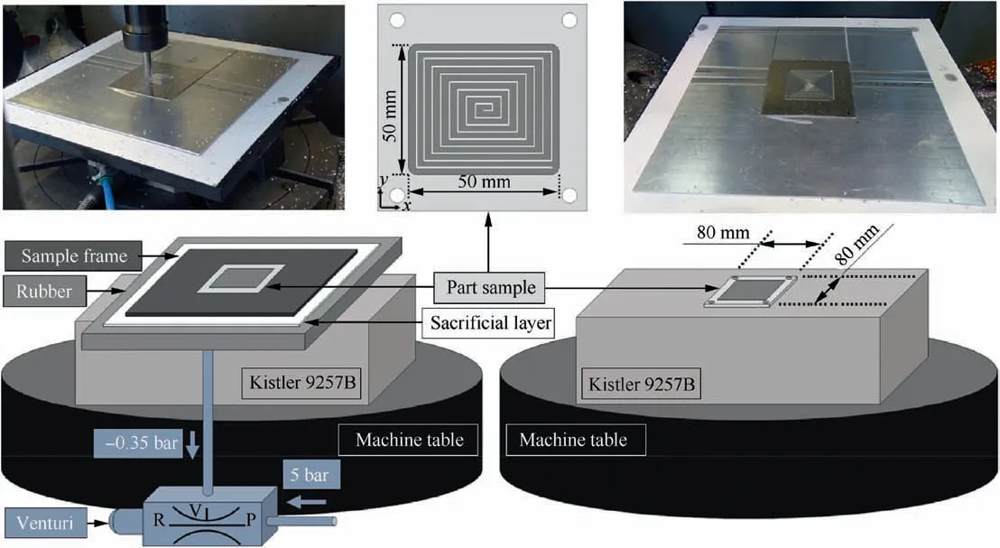
Fig.2 Set-up for pocketing tests with and without rubber.
As it can be observed in the Fig.3,the set-up is analogous to the pocketing test bench.The main difference is that the part sample is 240 mm×240 mm wide.The grooves are dry machined side to side,in two steps.First,a 0.2 mm depth groove is performed in order to guarantee the same initial profile between tests and a depth of cut tolerance under±0.1 mm.Then,the test with each condition is milled.The separation between each groove is 10 mm.For each milling condition,three repetitions are performed in different random positions relative to the part centre.
The part stiffness analysis is performed in two different thicknesses:2 and 20 mm.The depth of cut is maintained constant at 0.8 mm,right under the chatter zone.The feed per tooth is kept constant at 0.1 mm/tooth.Thus,the influence of the cutting speed is analysed for both stiffness cases by testing three equidistant spindle speeds.
2.4.SLDS calculation
Based on the three-dimensional dynamic force model proposed by Campa et al.36the stability lobes of the different parts are calculated and implemented for the prediction of chatter vibrations during the finish milling.Thus,the system axes defined for this model and the cutting forces(tangential Ft,radial Frand axial Fa)orientation for the cutting edge i of the tool can be observed in the Fig.4.
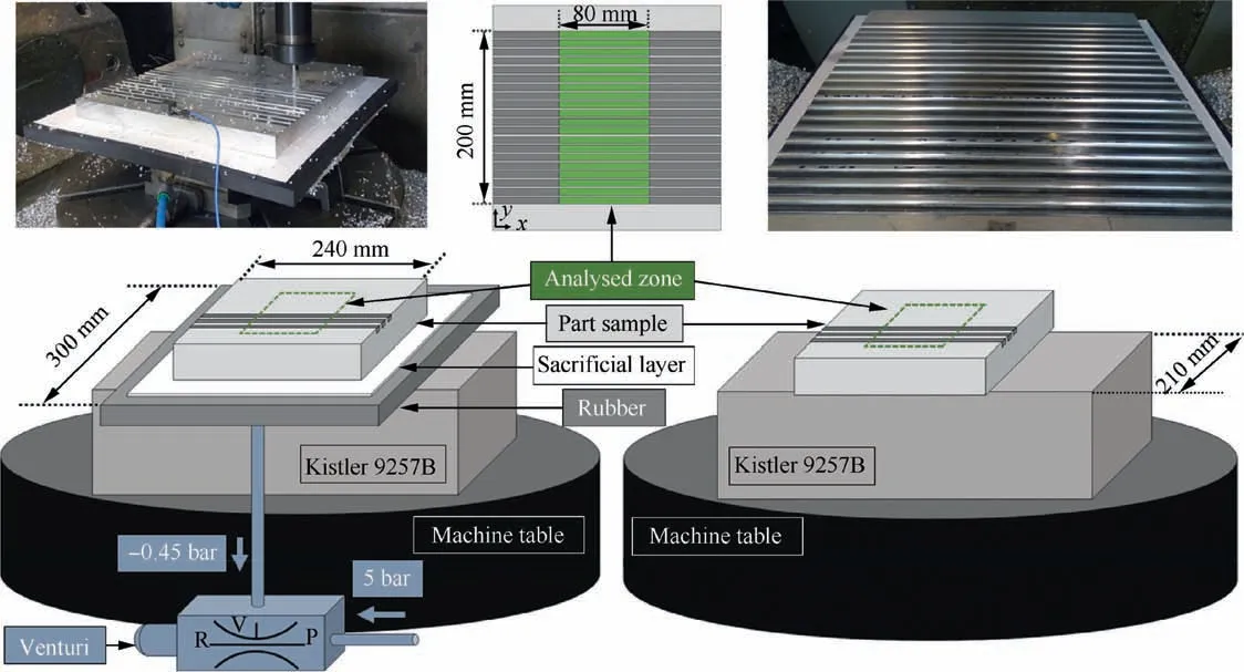
Fig.3 Set-up for groove machining with and without rubber.
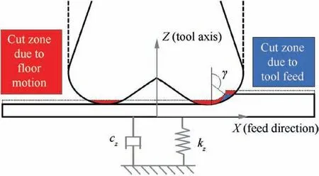
Fig.4 Milled zones generated by axial motion of part sample.
The Eq.(1)associates the cutting forces with the shearing cutting coefficients(Ktc,Krc,and Kac)and the friction coefficients(Kte,Kre,and Kae).

∂S is the differential chip edge length andφiis the angular position of the cutting edge i measured from axis Y.This angle depends on the instant depth of cut(z),the number of teeth engaged(j),the total number of teeth(N)and the helix angle(β).

The cutting forces are projected over the system axes as presented in the Eq.(3),with defining the angle of the toroidal zone of the mill.

Bull-nose end mills have a variable lead angle from 0° to 90°.37In order to solve the nonlinearity of the lead angle and the depth of cut,Altintas38simplified the radial insert geometry by defining an average edge angle of 45°.Thus,in this case,the edge angle is defined as 20°,as it represents a 0.6 mm depth of cut,the mean value defined in the working range.The same criterion is followed by defining the spindle speed to 4000 r/min.The Table 2 show the calculated cutting and friction coefficients.These values are obtained with the force measurement obtained in the grooving tests performed with no rubber at three different depths of cut and feed per tooth equally separated within the working range.Thus,the obtained coefficients are considered constant for all the milling conditions and the results are employed to predict the SLD for each set-up.
2.5.Roughness model
The floor roughness is caused by three different processes.First,the theoretical average roughness(Rh)is generated by the tool geometry and the feed per tooth.Then,the rest of the increase in the mean roughness is associated with the axial movement between the part and the tool.
Due to the high difference of the axial stiffness between the tool and the part-fixture system,the axial displacement of the tool is neglected.Thus,the movement of the part in the axis Z is associated to the sample part vibration.This vibration increases the floor roughness and is generated by a combination of the compression of the rubber(Rr)and the relative displacement between the part and the fixture(Rf).Thus,the global average roughness Racan be defined as:

The bull-nose end-mill tip geometry for the grooving operation is defined by the edge radius,and thus,the floor theoretical average roughness for the feed per tooth is presented in the Eq.(5).

The rheological model of a rubber compression can be obtained from the parallel contribution of the elastic(el),viscoelastic(ve)and elastoplastic(ep)stress contributions.29First,elastic behaviour is defined by the linear relation between the axial compression and the applied load,also known as Hooke’s Law.On the other hand,viscoelastic component is a rate dependent mechanism responsible for the fixture damping and for the reduction of the generated roughness.Similarly,the elastoplastic component of the strain is amplitude dependent and contributes to the system damping as considered in the Eq.(6).

Based on the system characteristics and the working range,the rheological model of the rubber is simplified.In this case,due to the selected machining conditions and the reduced axial compression strains both,the viscoelastic and elastoplastic components of the roughness,are considered uniform for all the working range.Moreover,due to the viscoelastic behaviour of the rubber,the influence of the loads in the fixture damping capacity decrease with the rise of the frequency and,therefore,with the tool rotation speed increase.Thus,for this model,the loads and the roughness are considered generated once per tool rotation rather than by the impact of each tooth,as shown in the Fig.5.


Table 2 Cutting force coefficients for the bull-nose end mill cutting tool.
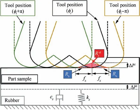
Fig.5 Roughness generated by tool feed(Rh)and by the rubber elastic compression().

The elastic behaviour of the rubber layer is based on a linear relation between the stress and the strain.Thus,the rubber axial compression strain is defined in the Eq.(8),where E is the Young’s modulus,l is the rubber layer mean thickness value and Aiis the area of the rubber influence zone.This area is the fixture zone where the rubber compression is focalized.

Finally,the relative displacement between the part and the fixture is dependent of the vacuum clamping suitability.In this case,the part-rubber mutual geometrical adaptation is a key factor that influence that union and the Rfreduction.Hence,the applied axial forces,the part stiffness and the rubber hardness determine the fixture influence area Aiand the clamping suitability as shown in the Fig.6.
The milling of high stiffness part samples leads to a progressive evolution of the fixture influence zone with the axial forces,regardless the hardness of the rubber.Thus,the axial loads and the influence area relation are as considered in the Eqs.(9)and(10),where A is the total area of the part:

However,in the case of low stiffness part sample,the increase of the fixture influence zone depends on the rubber.Thus,the utilization of a soft rubber lead to the relations shown in the Eqs.(11)and(12),as there is a critical force(Fz_-cr)from which the deflection of the part sample involves a steep increase of the influence zone.Moreover,it can be considered that,due to the cylindrical shape of the tool and the part deflection,the influence area is underneath the squared part total area A.

In the other hand,machining low stiffness parts with the hardest rubber provide that acute increase of the influence zone with lower forces as shown in the Eqs.(13)and(14).The reason to this behaviour is the higher local resistance to the rubber to be compressed.

3.Results and discussion
3.1.Effect of feed rate
The stress-strain curves differ between both elastic materials.In order to emphasize these differences a 5th degree interpolation is selected.Thus,as shown in the Fig.7,NBR90 has higher elastic modulus and a more lineal behaviour within the tested range.
However,the behaviour of the NBR65 compound is more feed rate dependent.This effect is normally related to the resistance caused by the reorganization of the polymeric chains during a force application.29Thus,for feed rates higher than 800 mm/min both elastic materials have similar behaviour under 0.3 MPa.
3.2.Effect of part sample material loss
First,as shown in the Fig.8,the SLDs for the three different systems are calculated in order to guarantee chatter-free machining conditions.The tests are performed before and after the pocketing.Results show that before the material is removed,rubber-based solutions provide a 15% improvement in the chatter suppression capacity.However,after the pocketing,these flexible solutions reduce the admissible depth of cut more acutely than the screwed part,specially the hardest rubber.
This decrease is produced by the influence of the part material loss in combination with the reduction of the clamping capacity,meanly with the NBR90 fixture.However,as the values remain over the part sample thickness,chatter-free conditions are maintained regardless the depth of cut.
Hence,the systems vibration is mainly produced by the force harmonics.This effect can be clearly observed in the floor roughness profile and its Fast Fourier Transform(FFT),as observed in the Fig.9.With a 0.1 mm/tooth feed rate the tool rotates five times per mm generating the theoretical roughness Rh.However,as the part vibration rises,Rrand Rfincrease.This roughness is generated between the theoretical profile and,thus,the impacts are doubled.
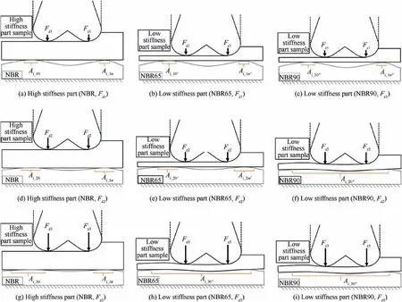
Fig.6 Clamping suitability evolution for high and low stiffness parts with NBR65 and NBR90 fixtures.
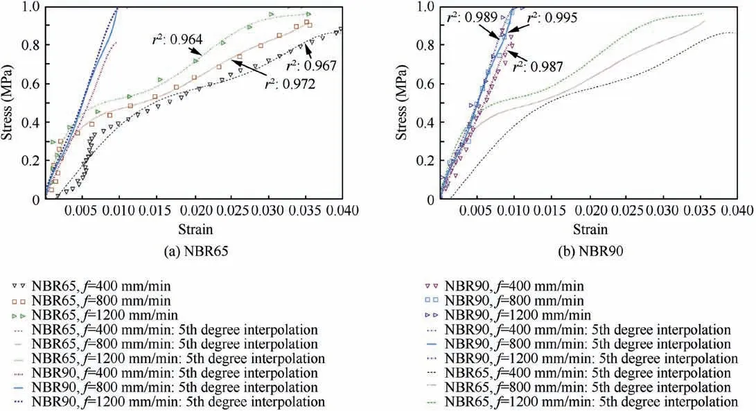
Fig.7 Compression tests results.
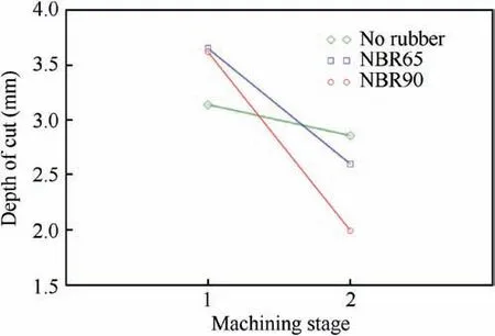
Fig.8 Stability Lobe Diagram(SLD)mean value before(machining stage 1)and after the pocketing(machining stage 2)at 4000 r/min.
There is an opposite evolution between the case with no rubber and the NBR90 compared with the NBR65.As it can be observed in the Fig.10,lower depth of cuts lead the softer elastomer to a more stable behaviour.However,as the material removal rate(MRR)increases,the roughness rises nearly linearly with the mean axial force and the part stiffness loss.
However,for the NBR90 there is a trend deviation after a 0-4 mm depth of cut.As defined in the roughness model section,the reason of this abrupt variation is the generation of a sudden change in the clamping conditions due to the increase in the axial force and the part deflection.A similar effect of stiffen the system through the tool loads is what improves the roughness in the case without rubber.Hence,as long as a proper clamping conditions are guaranteed,a harder rubber provides better quality in the part,as it behaves closer to a rigid fixture.
3.3.Effect of part sample stiffness
In this case,the area and the process forces are increased to focus the analysis in the part sample stiffness.First,as shown in the Fig.11,the SLD of each system is calculated for the grooving application.The systems with rigid parts behave like a rigid fixture in terms of chatter.However,as the stiffness of the part sample decrease,the rubbers damping properties arise.Thus,in the working range,NBR90 fixture provides up to 8%better damping capacity,while the soft rubber increases the chatter-free working depth up to 21%.
The following tests are focused in the softest rubber as is the most dependent of the harmonic loads and guarantee a proper clamping condition for the studied area and chatter-free milling conditions,as the depth of cut is 0.8±0.1 mm.The combined effect of the cutting speed and the part sample stiffness is analysed in terms of the axial forces applied by the tool.These forces are divided in the mean value and the extra loads generated by each tooth impact against the part sample,defined and limited as max and min.
As it is shown in the Fig.12,the forces are higher in the more rigid part.This effect was previously observed by Lo´pez de Lacalle et al.39as the cutting forces decreased with the part stiffness reduction.Moreover,Del Sol et al.35identified an opposite tendency of the axial forces between a low and high thickness test samples for cutting speeds under 378 m/min.
In order analyse the effect of the cutting speed and the part sample stiffness on the floor roughness in groove machining,an analysis of variance(ANOVA)is employed.First,normal distribution of the data is checked by the Anderson-Darling(AD)test,and the variance homogeneity with the Barlett test.In both cases,the confidence intervals of 90%(α=0.1).As it can be observed in the Table 3,for all the tests their p-values are overαand,thus,are suitable for an ANOVA.
On the other hand,a variance analysis is performed to determine the main parameters having effect on the roughness.In this case,the null hypothesis is that the factors or their combination have no influence over the thickness error.As it is detailed in the Table 4,from this survey it is obtained that,with a 90% confidence,the roughness is mainly dependent of the part thickness rather than of the cutting speed.
Thus,the roughness results show a clear differentiation between the two analysed part thicknesses.As it can be observed in the Fig.13,the case of thin part presents higher Ravalues than the test performed over a rigid sample.However,the low stiffness system tends to maintain a uniform mean quality value as the cutting speed increases.On the other hand,the roughness values of the rigid part floors increase with the tool rotation speed.Furthermore,the obtained values are under 1.6μm for the Ra,the typical tolerance defined in the aeronautical industry.35
The behaviour of both systems,as explained in the roughness model section,is caused by three sources.In the Fig.14 it can be observed the roughness ratio for each phenomenon for the case of the rigid part milling.The damping effect of the viscoelastic and elastoplastic source has not been integrated as it has been considered equivalent for both systems.The analysis has been developed based on the roughness model for the upper and lower axial force limits and under different hypothesis defined by the rubber influence areas compared with the total area of the part.Thus,the theoretical roughness ratio,in blue,is reduced as the global roughness increase due to the part vibration intensification with the cutting speed.Moreover,the model predicts that the rubber influence zone for this system must be over the 0.1% of the part area,as the roughness generated by the displacement between the part and the fixture,in green,cannot be negative,see Fig.14(a)and(d).Finally,as the influence zone is extended,the roughness generated by the elastic compression of the rubber,in red,decrease acutely.
The case of the low stiffness parts presents that the roughness generated by the part vibration is higher,and thus,the theoretical roughness ratio is lower than in the previous case,as shown in the Fig.15.However,the model validates the presence of a very reduced rubber influence area,even under 0.1% of A.This leads to a more stable part vibration that could be even reduced for higher cutting speeds.Moreover,with lower limit forces,for cutting speeds over 126 m/min,there is an acute vibration decrease.This roughness reduction is mainly generated by a sudden clamping condition improvement.
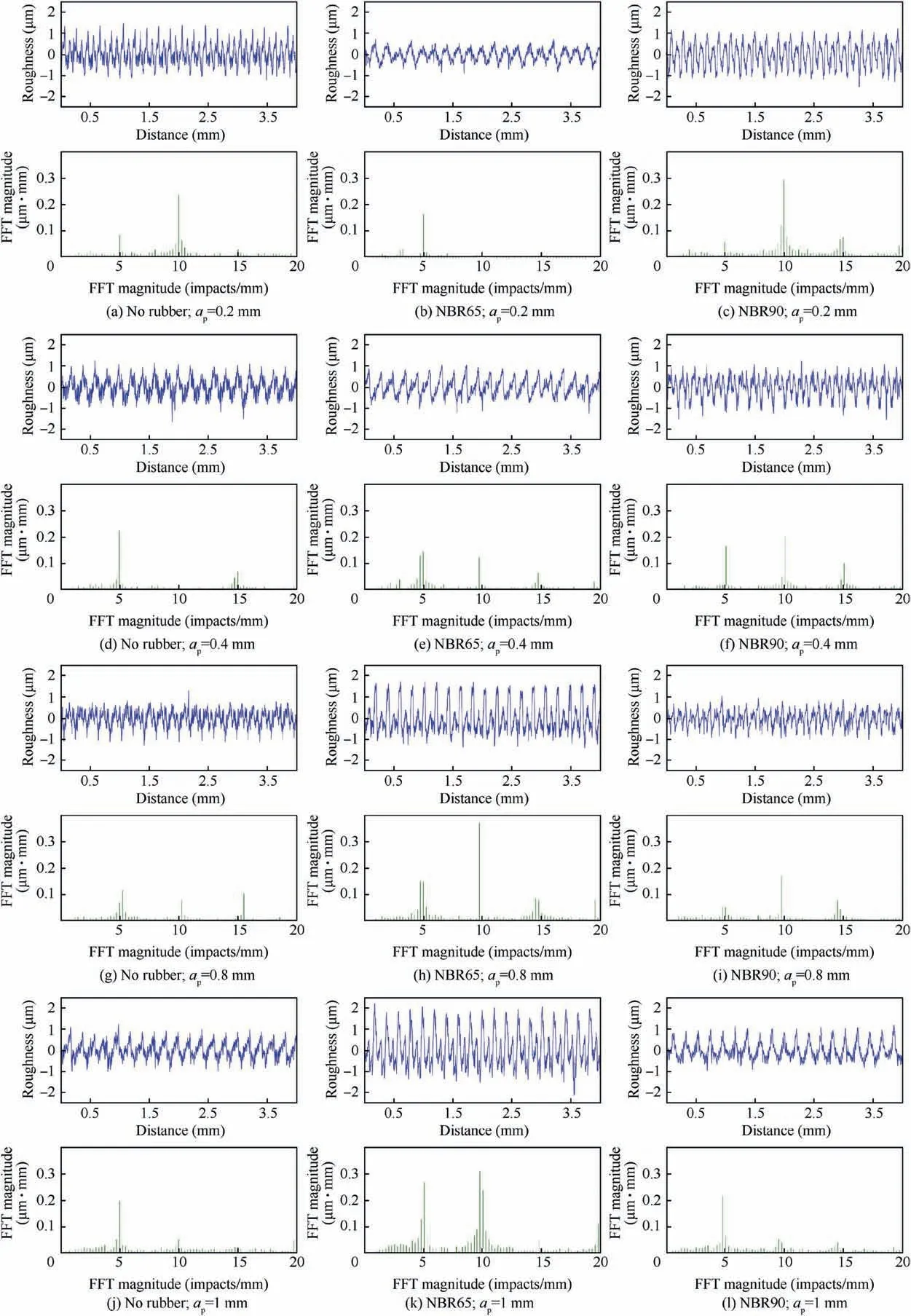
Fig.9 Effect of depth of cut in floor roughness.
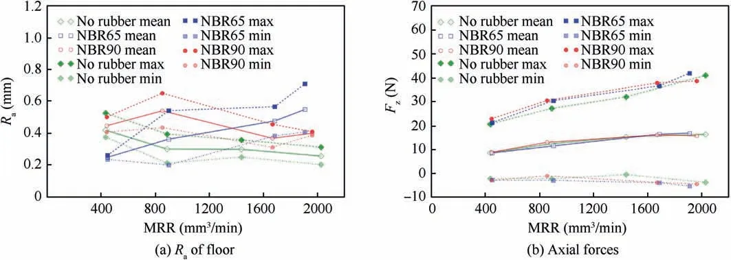
Fig.10 Material removal rate(MRR)effect.

Fig.11 SLD variation for each clamping material.
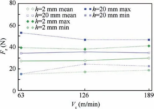
Fig.12 Part thickness and cutting speed effects on axial forces.

Table 3 Analysis of suitability of roughness data in slot milling tests with a NBR65 fixture.
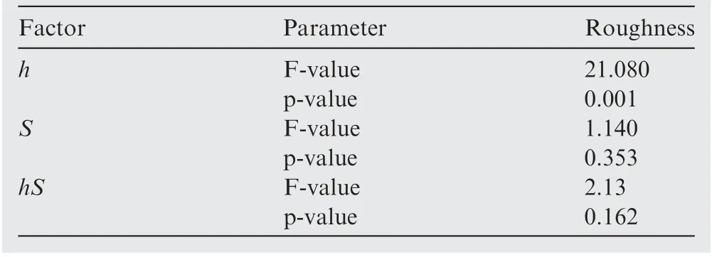
Table 4 Analysis of variance of thickness error and roughness data in slot milling tests with a NBR65 fixture.
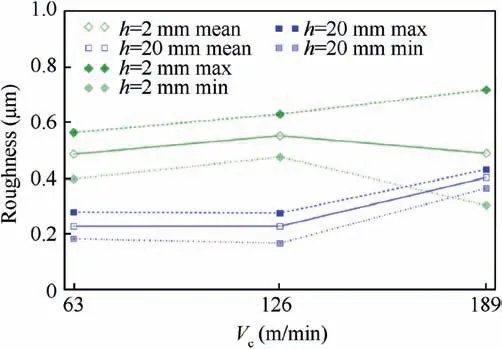
Fig.13 Part thickness and cutting speed effects on roughness.
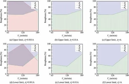
Fig.14 Roughness distribution for h=20 mm under different influence area.
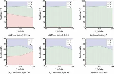
Fig.15 Roughness distribution for h=2 mm under different influence area.
4.Conclusions
In this work the behaviour of a rubber-based vacuum fixture is characterized under the loads generated on the milling process is characterized.The main outcomes of the paper are as follows:
(1)By means of different compression tests implemented over the fixtures,the stress amplitude and feed rate effects are analysed.Thus,the elastic modulus rises as the rubber hardness and strain rates increase.
(2)The effect of sample material loss and thickness are modelled and analysed in terms of the floor quality.The roughness is generated by three sources:the feed per tooth,the rubber compression and the relative movement between the part and the fixture.The rubber compression has an elastic component that increase the roughness while the viscoelastic and elastoplastic components absorb the part vibrations.Thus,the results show that rubber-based fixtures improve damping capacity of the part-support systems and prevent chatter for finishing operations.Hence,in order guarantee a proper part quality,the effect of the forced vibrations must be managed.
(3)In the case of hard rubbers,the main factor is the generation of suitable clamping conditions to obtain a near rigid behaviour of the fixture.This can be obtained with higher material removal rates.
(4)Soft rubbers facilitate these suitable clamping conditions.However,in this case,there is a higher influence of the forced vibrations caused by the rotating tool.This effect can be reduced by the process forces reduction and the rubber influence zone expansion.
All these solutions to improve the part quality are aligned with the milling process of low stiffness parts performed in the aeronautic industry.First,the material removal rate employed in aeronautics machining,such as aeronautic skin milling,can be higher than the values tested.For instance,the feed rates can reach ten times these values and the tools employed in these applications are up to∅40 mm.Hence,the rubber influence zone is expanded,and the force increasement will be compensated with a higher damping capacity of the fixture.Finally,the wide range of different references in the aeronautic field presents an opportunity for these rubberbased clamping solutions as there is no need of‘‘ad-hoc”fixtures.Thus,this solution,combined with a proper part monitoring system,could be employed in the manufacturing of aeronautic skins and the thickness and roughness tolerances could be reached.
Acknowledgement
Financial support from the Basque Government under the ELKARTEK Program(SMAR3NAK project,grant number KK-2019/00051)is gratefully acknowledged by the authors.
 CHINESE JOURNAL OF AERONAUTICS2021年6期
- CHINESE JOURNAL OF AERONAUTICS的其它文章
- Performance evaluation of creep feed grinding ofγ-TiAl intermetallics with electroplated diamond wheels
- Thermomechanical coupling effect on characteristics of oxide film during ultrasonic vibration-assisted ELID grinding ZTA ceramics
- Modeling and experiment of grinding wheel axial profiles based on gear hobs
- Electrochemical machining on blisk channels with a variable feed rate mode
- Framework and development of data-driven physics based model with application in dimensional accuracy prediction in pocket milling
- Electrode design using revolving entity extraction for high-efficiency electric discharge machining of integral shrouded blisk
