Milling surface roughness for 7050 aluminum alloy cavity influenced by nozzle position of nanofluid minimum quantity lubrication
Zhnjing DUAN,Chngh LI,*,Ynin ZHANG,Ln DONG,Xiung BAI,Min YANG,Dongzhou JIA,Runz LI,Hujun CAO,Xung XU
a School of Mechanical and Automotive Engineering,Qingdao University of Technology,Qingdao 266520,China
b School of Mechanical and Electrical Engineering,Qingdao Binhai University,Qingdao 266555,China
c School of Mechanical Engineering,Inner Mongolia University for Nationalities,Tongliao 028000,China
d Department of Biomedical Engineering,University of Southern California,CA90089-1111 Los Angeles,USA
e State Key Laboratory Mechanical Transmiss,Chongqing University,Chongqing 400044,China
f Zhejiang University of Technology,Hangzhou 310032,China
KEYWORDS
Abstract In nanofluid minimum quantity lubrication(NMQL)milling of aviation aluminum alloy,it is the bottleneck problem to adjust the position parameters(target distance,incidence angle,and elevation angle)of the nozzle to improve the surface roughness of milling,which has large and uncontrollable errors.In this paper,the influence law of milling cutter speed,helical angle,and cavity shape on the flow field around the milling cutter was studied,and the optimal nozzle profile parameters were obtained.Using 7050 aluminum alloy as the workpiece material,the milling experiment of the NMQL cavity was conducted by utilizing cottonseed oil-based Al2O3 nanofluid.Results show that the high velocity of the surrounding air flow field and the strong gas barrier could be attributed to high rotating velocities of the milling cutter.The incidence angle of the nozzle was consistent with the helical angle of the milling cutter,the target distance was appropriate at 25-30 mm,and the elevation angle was suitable at 60°-65°.The range and variance analyses of the signal-to-noise ratio of milling force and roughness were performed,and the chip morphology was observed and analyzed.The results show that the optimal combination of nozzle position parameters was the target distance of 30 mm,the incidence angle of 35°,and the elevation angle of 60°.Among these parameters,target distance had the largest impact on cutting performance with a contribution rate of more than 55%,followed by incidence angle and elevation contribution rate.Analysis by orthogonal experiment revealed that the nozzle position parameters were appropriate,and Ra(0.087μm)was reduced by 30.4% from the maximum value(0.125μm).Moreover,Rsm(0.05 mm)was minimum,which was 36%lower than that of the seventh group(Rsm=0.078 mm).©2020 Chinese Society of Aeronautics and Astronautics.Production and hosting by Elsevier Ltd.This is an open access article under the CC BY-NC-ND license(http://creativecommons.org/licenses/by-nc-nd/4.0/).
1.Introduction
Aviation aluminum alloy is widely used in automobile,mold,aviation,and other industries because of its high strength,low weight,and low cost.1-3In the aerospace field and automobile manufacturing industry,aviation aluminum alloy is mostly processed into cavity-type structural parts,such as aircraft wall panels,grille structures,trusses,and wing spars.The aviation manufacturing industry has achieved high processing precision and quality requirements due to the high pressure resistance,stability,and surface quality requirements of these structural parts by the working environment.4The manufacturing quality of aviation aluminum alloy components determines service life,impact conditions,mechanical wear,corrosion,and environmental and chemical degradation resistances of components under cyclic load.5-7Guaranteeing surface integrity has become the primary task of researchers with the increased attention provided to the working reliability of machined structural parts in machining.8-10Kishawy et al.studied the application of different cooling methods to high-speed milling of A356 aluminum alloy and analyzed tool wear and cutting forces,surface roughness,and chip morphology in dry cutting,flood,and minimal quantity lubrication(MQL).11Rahmati et al.compared ordinary lubricants and additives containing different concentrations of MoS2nanoparticles of trace lubricants in Al6061-T6 alloy milling machining workpiece surface topography.They also added nanoparticle concentrations of 0.5% according to the experimental results.Their results showed that surface quality was superior to pure oil or other nanoparticle concentration processing.12Khettabi et al.studied the properties of MQL and dry milling for 7075,6061,and 2024 aluminum alloys and found that MQL milling could reduce cutting force and improve surface finish.13
Milling is a removal process widely used in various materials.In milling,the rake face of milling cutter and chip,the flank surface of the cutting tool,and the processed surface will produce a large friction force.Such a force not only increases cutting heat,cutting force,and workpiece deformation but also aggravates the tool wear and affects the quality of the processed surface.14-16In traditional machining,the main cooling and lubrication methods include injection of cutting fluid and natural cooling methods.The natural cooling method has a relatively small scope of application due to the limitation of its own conditions.The method of adding cutting fluid also has many shortcomings in cutting.First,high energy consumption increases the cost of manufacturing parts.Second,the spatter of cutting fluid is not conducive to worker observation and monitoring of the machining area.17The base oil and additives will also affect the health of workers because of the pollution to the environment.In addition,water-based cutting fluid causes deterioration and even corrosion of machine tools.18-22
In this context,a green cutting technology,MQL cutting,was introduced.MQL technology was proposed by the Michigan Technological University scholars W.D.Hewson and G.K.Gerow in 1996.This technology is a type of cooling and lubrication between flood and dry types of technology that possesses the advantages of the flood and the dry types.23-27Moreover,this technology mixes minimum quantity lubrication with the gas of a certain pressure for atomization and sprays the mixture into the cutting area to exert cooling and lubricating effects.28-32The lubrication accuracy,transmission,and penetration efficiency of lubricating oil drops can be improved by optimizing the nozzle position.33-36Tawakoli et al.analyzed the nozzle position through modeling and grinding experiments.37Their results showed that nozzle distance was the key to improving oil mist penetration.Comaro described the effects of relative curvature,nozzle diameter,nozzle-to-surface distance,and Reynolds number on the jet flow structure.38Mulyadi et al.elucidated the effect of spindle rotation speed on the sensitivity of nozzle location in order to enhance machining performance,which increased tool life by 50%.39Yan et al.found that the relative nozzle-feed position at 120°,the angle elevation of 60°,and the distance from nozzle tip to cutting zone at 20 mm prolonged tool life and reduced surface roughness values.40The nozzle position can improve the transmission and penetration efficiencies of oil droplets in MQL cutting and the surface quality of the workpiece.34,41
However,most of the literature focus on the study of nozzle position of end milling,and the parameters of nozzle position(target distance,jet angle,and elevation angle)are not fully considered.Several sources of parameters have no basis and are only explored by experiments.Thus,the Fluent module in Ansys workbench was used to simulate the dynamic characteristics of the air flow field around the milling cutter to reveal the flow field distribution in the milling area under milling conditions effectively.This simulation has guiding significance for further optimizing the jet parameters.The influence of milling cutter speed and helical angle and cavity size and shape on the air flow field around the milling cutter was analyzed to determine the appropriate nozzle attitude and improve the use of lubricating oil droplets in the contact area between the milling cutter and the workpiece.Orthogonal experiments were conducted on the milling of 7050 aviation aluminum alloy by square cavity based on the position parameters obtained from computational fluid dynamics(CFD)simulation analysis.These experiments aimed to verify the parameters obtained from simulation analysis and analyze the significance of each nozzle position parameter.
2.Finite element simulation analysis
2.1.Physical modeling of milling area
In the milling process,the spindle drives the high-speed rotation of the milling cutter,and the rotating motion disturbs the surrounding air.These phenomena create an air boundary layer around the milling cutter and impede the cutting fluid from entering the processing area.The milling cutter blade part of the milling cutter groove forms the rotary flow along the direction of the groove,which has a blocking effect on the supply of cutting fluid.
The simulation parameters are provided in Table 1,and the established physical model is shown in Fig.1.The coordinate system is the same as the milling machine coordinate system,where X′represents the negative half cycle of X.
2.2.Simulation results of air flow field in milling area
The physical model in Fig.1 shows the simulation performed using the 3D solver to calculate the standard k-epsilon model and flow field of air medium choice.The outlet boundary and the workpiece boundary condition are respectively set to the pressure outlet boundary flow field and stationary wall.The milling cutter is set to the rotating wall boundary condition,and the boundary condition is initialized.Finally,residual monitoring is set,and the solution is calculated.The simulation parameters are presented in Table 2.The medium of the flow field is air.The simulation results are shown in the figure below.Figs.2 and 3 respectively present the flow diagrams of the air flow field in the milling area and at the XY section of the cutter tip.Fig.4 is a local enlarged drawing of air flow field at 35°.
Figs.3 and 4 show that the air flow velocity close to the milling cutter is the largest in the established calculation area;as the distance from the center of the milling cutter increases,the air flow velocity gradually decreases until it drops to 0.A closed‘‘ring”area is formed around the milling cutter,creating an air barrier as shown in Fig.2.This barrier will block the lubricating oil into the cutting area.Thus,the lubricating oil cannot fully achieve the milling cutter-chip and the milling cutter-workpiece interfaces,reducing the cutting medium cooling and lubrication effects.Return flow will be formed after the airflow reaches the surface of the workpiece due to the existence of the workpiece.This flow will also hinder the entry of lubricating oil,as shown in Fig.4.
According to the study,42among the nozzle position parameters,the target distance,which is the distance fromthe nozzle to the milling cutter tip,has the largest influence on the cutting performance,followed by the incidence angle between the nozzle and the feed direction of the tool and the elevation angle of the nozzle.The elevation angle is the angle between the nozzle and the upper surface of the workpiece.First,the incidence angle is determined.Then,the section perpendicular to the upper surface of the workpiece is identified according to the incidence angle.Finally,the nozzle elevation angle is determined according to the flow velocity diagram in this section.Fig.3 shows that the air flow field is helical in the circumferential and milling cutter feed directions along the Y-axis forward.When the MQL jet is pointed to the tip of the milling cutter and the jet direction is tangent to the streamline of the air flow field,the cutting fluid is injected in the air flow direction.The air flow field will play an auxiliary role in the injection of cutting fluid transport,which can transfer additional cutting fluid to the milling cutter-workpiece interface.At this point,the nozzle incident angle,which is 35°from the feed direction of the milling cutter,is the best incidence angle.

Table 1 Simulation parameters.

Fig.1 Physical model.

Table 2 Simulation parameters.
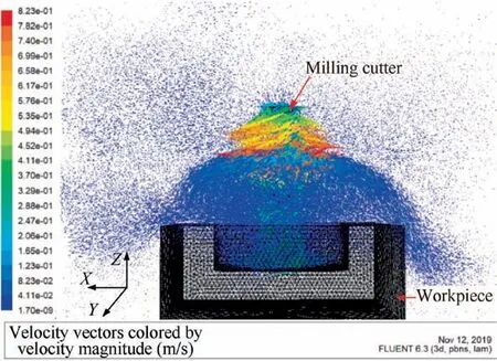
Fig.2 Streamline diagram of air flow field in milling area.
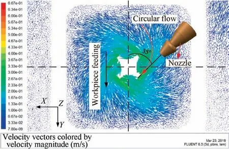
Fig.3 Streamline diagram of air flow field at the XY section of cutter tip.
Fig.5 shows the schematic of seven measuring transversals at different distances from the center of the milling cutter in the 35° section.This schematic is used to study the position where the return flow occurs and the thickness of the radial flow in the milling flow field quantitatively.The seven measuring transversals(Mt)are 8,10,12,15,20,25,and 30 mm from the center of the milling cutter.
The angle between the nozzle and the horizontal direction,namely,the elevation angle,will also influence the injection of cutting fluid.Therefore,the cross-sectional flow field at 35° is further analyzed.Fig.4 shows that the outermost layer is the air barrier,which prevents the cutting fluid from entering the cutting zone;hence,the position of the nozzle should avoid the air barrier.Cutting fluid through the radial flow transport arrives in the cutting area.A portion of the cutting fluid will adhere to the surface of the workpiece,forming a dense layer of lubricating oil film,which has the effect of anti-friction and anti-wear.A part of the cutting fluid flows along with the‘‘return flow”.According to the measurement,when the incidence angle is approximately 35°,the elevation angle is 60°-65°,the target distance is 25-30 mm,the flow field will transport the cutting fluid,and the‘‘return flow”will slightly hinder the cutting fluid less.Thus,entry to the cutting zone will be easy for the cutting fluid.

Fig.4 Local enlarged drawing of air flow field at 35°.

Fig.5 Diagram for measuring transversal.
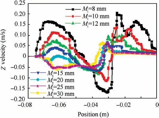
Fig.6 Speed curve of Z on seven transversal lines.
Fig.6 shows the Z velocity curve of the seven intercept lines.According to the analysis,on the section of 35°,the velocity direction points to the milling cutter when the Z velocity is positive,representing entry flow.When the Z velocity is negative,the flow goes out of the milling cutter,representing the return flow.The size of the x-axis represents the distance from the workpiece surface,where x=-0.075 m denotes the inner bottom of the cavity.A large X results in farther distance from the workpiece surface.According to Fig.5,on the intercept line(L=8 mm)from the center of the milling cutter,when-0.075 m<x<-0.045 m(that is,when X is 0-30 mm),the Z-direction velocity is positive,the air flow velocity is maximum,and no return flow occurs.However,when X is 30-50 mm,the Z velocity has a negative value,and the return flow appears;when x>-0.025 m,the return flow disappears again.When L=10 mm,the Z-direction velocity is positive,and the thickness of the entry flow is 25 mm.At the line of L=13 mm,when X is 0-23 mm,the velocity is positive,and the airflow is the entry flow.When X>13 mm,the velocity is negative,and the airflow is the return flow.At the line of L=15 mm,the range of the entry flow is 0-20 mm.When x>20 mm,the air flow is the return flow.When L>20 mm,-0.075<x<-0.04,and Z-direction velocity is negative.Thus,they are all considered return flow,and the speed of return flow is small with the distance from the milling cutter.
The pressure distribution around the milling cutter was further analyzed.Fig.7 shows that in the 35°section,air pressure is negative on the eight transversal lines(6,7,8,10,15,20,25,and 30 mm)away from the center of the milling cutter;the air pressure is small when the distance is close to the milling cutter.The minimum pressure is in the milling groove;when the air pressure is large,the distance is far from the center of the cutter air pressure.Under the action of the pressure difference,the air may enter the cutter-workpiece surface.
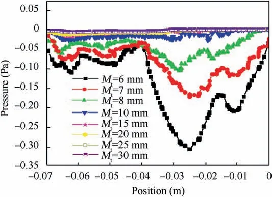
Fig.7 Pressure curve on eight transversal lines.
2.3.Influence factors of air flow field in milling area
2.3.1.Effect of milling speed on air flow field
Tool speed will have an impact on the air flow field in the milling area.15Under the condition that the tool diameter(12 mm),helicalangle(35°),squarecavity(60 mm×60 mm×20 mm),flow field height(150 mm),flow field diameter(200 mm),and other parameters remain unchanged,only the tool speed(1000,3000,5000,10,000,15,000,and 25,000 r/min)is changed to observe the changes in the flow field.The simulation results are shown in Figs.8 and 9.
Fig.8 is the streamline diagram of air flow field at the XY section of the cutter tip with different rotation speeds.The rotation speed does not affect the shape of the air flow field in the circumferential direction.Thus,the rotation speed of the milling cutter does not affect the angle between the nozzle and the feed direction of the milling cutter.Incidence angles of approximately 35° are favorable for cutting fluid injection.
Fig.9 shows that the entry flow increases with the milling cutter speed,whereas the air barrier flow speed gradually increases.This trend indicates that the increase in milling cutter speed will also increase the difficulty of cutting fluid entering the milling cutter-workpiece interface.Moreover,the best distance of the nozzle should be in the air barrier,and the maximum target distance should be within 30 mm.Considering the collision between the nozzle and the upper surface of the blank during milling,the target distance of 25-30 mm is appropriate under this cavity size.The rotation speed of the milling cutter does not affect the elevation angle of the nozzle.The angle of 60°-65° is favorable for the transportation of cutting fluid to the milling cutter-workpiece interface.
The air flow velocity and pressure around the milling cutter(L=6 mm)at different rotation speeds were collected to analyze the influence of rotation speed on the air flow field around the milling cutter quantitatively,and the air flow velocity and pressure diagram around the milling cutter at different rotation speeds were established.Fig.10 shows the difference between the abscissa,and-0.075 is the length from the bottom of the cavity.The air flow rate periodically changes with the distance from the workpiece surface.This periodic change is due to the following:when the milling cutter is spiral,the diameter of the milling cutter is 12 mm,the distance from the milling cutter center is 6 mm,the air flow velocity at the chip is collected,and discharging groove is obtained.Moreover,the blade position is solid,and thus,the air flow velocity tends to be zero.The air flow enters the narrow milling groove from the surrounding of milling cutter,and the air flow velocity around the milling cutter surface is relatively large.The air flow velocity can reach 0.91,2.03,3.26,6.63,9.60,and 15.62 m/s(n=1000,3000,5000,10,000,15,000,and 25,000 r/min,respectively).The influence of milling cutter on the surrounding air flow field becomes increasingly evident with the increase in rotation speed.The air flow field around the milling cutter increases with the milling cutter speed.This phenomenon indicates that the air barrier around the milling cutter will be enlarged with an increase in the rotation speed.Thus,reaching the interface between the milling cutter-chip and the milling cutter-workpiece to reduce the cooling and lubrication effects will be difficult for the cutting fluid.If the nozzle is placed in the direction of the entry flow,then the gas barrier layer will be avoided,and the entrance will be the workpiece surface along the entry flow and will play the role of air flow field in the transportation of cutting fluid.

Fig.8 Streamline diagram of air flow field with different rotation speeds.
In Fig.11,the air pressure around the milling cutter is negative,and the maximum pressure can reach-0.035,-0.4,-0.67,-1.42,-2.12,and-3.72 Pa(n=1000,3000,5000,10000,15000,and 25000 r/min,respectively)with the increase in the rotation speed of the milling cutter.The pressure difference of the entry flow increases with the negative pressure around the milling cutter.This condition is conducive to the transmission of cutting fluid to the milling cutter-workpiece interface with the incoming flow.
2.3.2.Influence of the spiral angle of milling cutter on air flow field
The helix angle of the milling cutter may affect the air flow field in the milling area.Therefore,under the condition that the cutter diameter(12 mm),milling cutter speed(2000 r/min),square cavity(60 mm×60 mm×20 mm),flow field height(150 mm),flow field diameter(200 mm),and other parameters remain unchanged,only the helix angle of the milling cutter is changed to 30°,35°,40°,and 45°.The change in the air flow field is also observed.
Fig.12 is the streamline diagram of air flow field at the XY section of the cutter tip of different spiral angle tool.This diagram shows that the direction of the circular flow changes with the helix angle of the milling cutter;that is,the incidence angle of the nozzle changes with the helix angle of the milling cutter.When the incidence angle of the nozzle is the same as the helix angle of the milling cutter,the air flow field will assist the transportation of the cutting fluid.Such assistance is beneficial to injecting the cutting fluid into the milling cutter-workpiece interface and increasing the effective utilization rate of the cutting fluid.
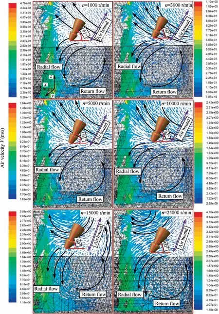
Fig.9 Streamline diagram of air flow field at 35° with different rotation speeds.
Fig.13 is the streamline diagram of the air flow field of the optimal jet angle section under different helix angles.When the incidence angle of the nozzle is the same as the helix angle of the milling cutter,the air flow field formed by the milling cutter rotating at different helix angles is slightly different.According to the measurement,the optimal target distance should be within 25-30 mm,and the elevation angle of the nozzle is 60°-65°.These conditions are conducive to the transportation of cutting fluid.
The air velocity and pressure around the milling cutter with different helix angles were collected to analyze the law of the air flow field around the milling cutter with different helix angles quantitatively.Fig.14 shows that different helix angles do not affect the maximum air flow velocity(approximately 1.25 m/s)around the milling cutter.Moreover,the maximum air flow velocity around the milling cutters with different helix angles can reach different lengths because the varying helix angles of the milling cutters lead to different axial thicknesses of the helix edge and the chip discharge groove.
Fig.15 shows that the pressure around the milling cutters with different helix angles is negative.The maximum value of negative pressure around the milling cutters with different helix angles is different.When the helix angle is large,the maximum value of the negative pressure is small.The maximum value can reach-0.095,-0.1,-0.11,and-0.115 Pa(β=30°,35°,40°,and 45°,respectively).
2.3.3.Influence of different shape cavity on air flow field
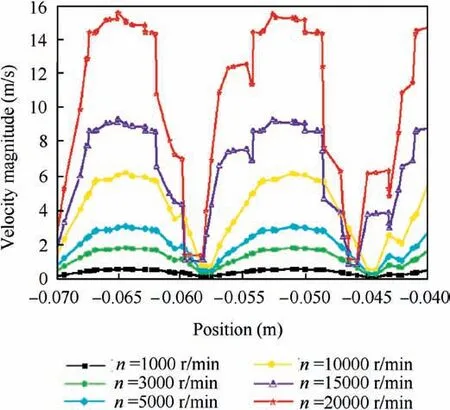
Fig.10 Speed of air flow around tool with different rotation speeds.
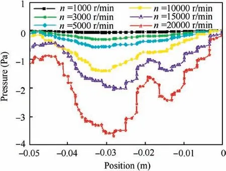
Fig.11 Pressure around tool with different rotation speeds.
Workpieces must be processed into various cavities during milling.Therefore,studying different cavities that affect the air flow field is necessary.In the simulation,circular,square,irregular,and quadrangular cavities are used to observe the change in air flow field.
The simulation parameters only change the shape of the cavity.The maximum dimension between the two walls of the cavity is the same(60 mm),and the depth of the cavity is 20 mm.The milling cutter with a 35° spiral angle is used,and the rotation speed is 2000 r/min.
Fig.16 is the streamline diagram of air flow field at the XY section of the cutter tip of different cavity shapes.This diagram shows that the direction of the circular flow does not change with the shape of the cavity,that is,the incidence angle of the nozzle is unaffected by the shape of the cavity.
Fig.17 shows that the air flow field around the milling cutter with different cavities has a minimal difference,the optimal target distance should be within 25-30 mm,and the elevation angle of the nozzle is 60°-65°.These conditions are all conducive to the transportation of cutting fluid to achieve high utilization.
The air flow velocity and pressure around different cavity milling cutters are collected to analyze the law of air flow field under the condition of different cavity shapes quantitatively in the milling cutter-workpiece restricted interface.Fig.18 shows that different cavities have no effect on the air flow speed around the milling cutter.Fig.19 reveals that different cavities do not affect the pressure around the milling cutter.
3.Orthogonal experiment of nozzle position in the cavity milling of 7050 aluminum alloy
3.1.Experimental setup

Fig.12 Streamline diagram of air flow field of different spiral angle tool.

Fig.13 Streamline diagram of air flow field in optimum jet angle section.

Fig.14 Speed of air flow around tool with different spiral angle tool.
The experiment was performed on a Dema ML1060B CNC milling machine.The parameters of the milling machine are shown in Table 3.The overall dimension is 3200 mm×2450 mm×2000 mm(L×W×H).The technological parameters include the following:principal axis power=11 kW,maximum speed=8000 r/min,motor power drivingtheworkbench=5 kW,cuttingrange=1000 mm×600 mm×600 mm,and cutting feed rate=10000 mm/min.Minimum lubrication oil was transmitted by JinZhao KS-2106 minimum lubrication system.Surface roughness was measured by TIME3220 contact pointer measuring device.During data collection,the three-phase milling force was measured by a piezoelectric three-phase measuring dynamometer.Debris surface topography was measured via scanning electron microscopy(SEM)using DV2TLV.The experimental and analysis equipment are shown in Figs.20 and 21,respectively.

Fig.15 Pressure around tool with different spiral angle tool.
3.2.Experimental materials

Fig.16 Streamline diagram of air flow field with different shapes of cavity.

Fig.17 Streamline diagram of air flow field at 35° with different shapes of cavity.
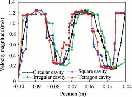
Fig.18 Speed of air flow around tool with different shapes of cavity.

Fig.19 Pressure around tool with different shapes of cavity.

Table 3 Parameters of Dema ML1060B CNC milling machine.
In the experiment,7050 aluminum alloy was used as the workpiece material.This alloy has been widely used in aircraft structures due to its perfect strength,fracture toughness,and high stress/density ratio after supersaturated solid solution and pre-stretchingtreatment.Theworkpiecesizeis 100 mm×100 mm×40 mm.The chemical composition and performance parameters of 7050 aluminum alloy are respectively listed in Tables 4 and 5.
Cotton oil,which served as the base oil of nanofluid MQL(NMQL),and Al2O3nanofluid,were used in the experiments.Nanoparticles with a concentration of 0.5wt% were mixed with cottonseed oil and dispersant(SDS)with a concentration of 0.3wt%and placed in the numerical control ultrasonic oscillator with ultrasonic vibration for 60 min.This mixture was used as the cutting fluid for NMQL.43,44Table 6 lists the physical,chemical,and mechanical properties of cotton oil.Table 7 presents the fatty acid composition of cottonseed oil.Table 8 lists the physical properties of nanoparticles.
This experiment adopted S550,a four-blade coated end mill of SGO.The end mill model was 12×12D×36C×75L.Diameter(R)and total length were 12 and 75 mm,respectively.The material was tungsten steel.The particle size was 0.6 UM.The helix angle was 35°.
3.3.Orthogonal experimental design for nozzle azimuth parameters
Orthogonal experimental design and analytical method(OEDAM)is a common means of process parameter optimization.This method is based on probability theory,mathematical statistics,and practical experience through the standard orthogonal table design test and the corresponding calculation and analysis to obtain optimization results quickly.OEDAM is an effective method to study multifactor and multilevel optimization problems.The orthogonal experiment of the position and orientation of 7050 aviation aluminum alloy square cavity milling nozzle with nanofluid micro lubrication was conducted to verify the results of CFD simulation analysis.Three parameters of nozzle position(target distance d,incidence angleβ,and elevation angleα)were analyzed by orthogonal test in this paper.45-48
The milling cavity is a square cavity.According to the simulation data and analysis of 2.2 square cavity,the nozzle target distance d(25-30 mm)and elevation angleα(60°-65°)are appropriate.The simulation analysis shows that the incidence angleβof the nozzle is approximately the same as that of the milling cutter helical angle.The milling parameters are shown in Table 9.
The aforementioned experiment aims to determine the influence of nozzle positions on MQL cutting performance according to the analysis of the air flow field around the milling cutter in the milling area.As shown in Table 10,the three factors of nozzle position parameters(target distance d,incidence angleβ,and elevation angleα)were taken as three levels.Therefore,orthogonal table L9(34)was selected in Table 11,and the interaction among the factors was incorporated into the error.
4.Experimental results
4.1.Milling force
The milling force can reflect not only the milling state in machining but also the lubrication properties of various cutting fluids.The improvement of lubrication performance leads to a reduction in cutting force,thus enhancing the cutting performance.Therefore,the study of milling force is of considerable importance to improve the machining of 7050 aluminum alloy.49,50
The milling force was measured thrice in each condition.The discontinuity of the contact between the cutter and the workpiece caused drastic changes in milling force because milling is a discontinuous cutting.The changing law of cutting force under different lubrication conditions is shown in Fig.22.The milling force shows an evident periodic change rule.
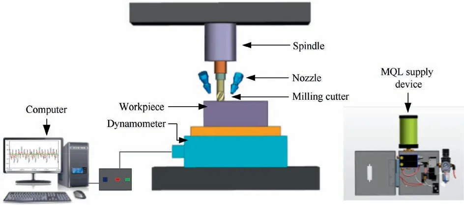
Fig.20 Experimental equipment.

Fig.21 Analysis equipment.

Table 4 Chemical composition of workpiece.

Table 5 Mechanical properties.
Fx>Fy>Fzfor the periodic peak value of milling force.Fzis considerably small so that no substantial changes are observed.In high-speed milling,the milling force is usually determined by the peak value(Fmax).The influence of six working conditions on the milling force was discussed with the mean value(F-max)of peak milling force as reference.where Fpiis the ith milling force peak in the milling force signal acquisition.


Table 6 Characteristics of cotton oil.

Table 7 Fatty acid of cottonseed oils(%).

Table 8 Properties of Al2O3 nanoparticles.
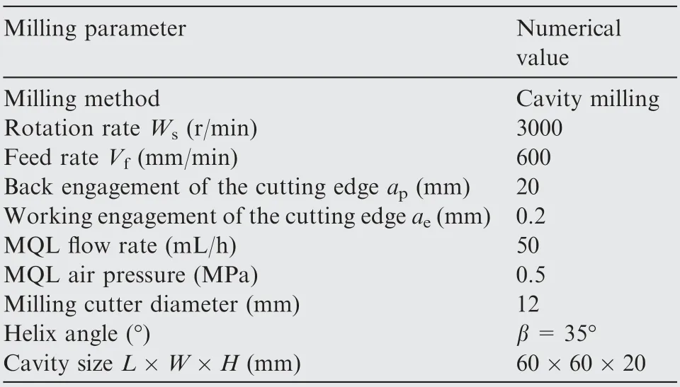
Table 9 Experimental parameters.

Table 10 Orthogonal experimental factor level table.
Fx,Fy,and Fz,which were collected by the measuring dynamometer and the calculated resultant milling force,were integrated into Eq.(1)to obtain the corresponding milling force peaks(Fig.22).
Fig.23 shows the milling component diagram,where Fyis small and was thus ignored.Fig.24 shows the resultant force of Fx,Fy,and Fz.In the second group of orthogonal experiment(d=30,β=35°,andα=60°),the minimum milling force is 104 N,which is 27.3%lower than the maximum value of the seventh group(d=50,β=15°,andα=70°).Moreover,Fxof the second group is the minimum value,which is 27.5% lower than the maximum value.According to the square simulation analysis,when the target distance is more than 30 mm,the nozzle is outside the air flow barrier,which hinders the oil mist transportation.The end milling cutter with 35°helix angle was used in this experiment.An incidence angle of 35° is appropriate according to the simulation analysis.Therefore,the incidence angle of the seventh group is smaller than that of the lubricating oil mist.Similarly,the seventh group of elevation angle is larger than the range of appropriate elevation angle and is unsuitable for entry into the milling area with the lubricating oil mist.
4.2.Surface roughness
Surface roughness is an important parameter for workpiece surface quality evaluation and determines surface smoothness.Surface roughness refers to a small space of the processed surface and size features of micro-geometry with tiny peak valley and unevenness.Low surface roughness reflects high surface smoothness.Surface roughness can influence fatigue strength,contact stiffness,and corrosion resistance of workpiece and considerably improve cooperation.Moreover,surfaceroughness influences the service life and reliability of machinery products.Poor surface quality will deteriorate workpiece performance,and the workpiece will fail before the expected life.

Table 11 Experimental scheme.
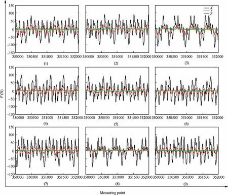
Fig.22 Original data schematic of the force.

Fig.23 Schematic of component force.
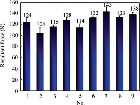
Fig.24 Schematic of resultant force.
The box diagram is used to analyze the roughness value obtained by orthogonal experiment,and the effective mass of roughness can be expressed.19Fig.25 shows that the second group of orthogonal experiments(d=30,β=35°,and α=60°)obtains the minimum roughness value.In the second group,the minimum Rais 0.082μm,the lower quartile is 0.085μm,the median is 0.087μm,the upper quartile is 0.09μm,and the maximum Rais 0.095μm.Moreover,the box diagram corresponding to the second group of experimental data is short and the data are concentrated.These findings indicate that the measured roughness value is uniform,and the surface quality of the workpiece is satisfactory.In the seventh group(d=50,β=15°,andα=70°),the median and the roughness value are large.The results show that the proper nozzle position is beneficial to the transportation of lubricating oil mist,and additional oil drops enter the milling area,which has a good lubricating effect.The seven other groups of experiments have different lubrication effects due to varying corresponding levels of several factors.
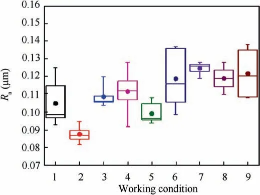
Fig.25 Ra under different working conditions.
On the workpiece surface after MQL milling,Rsmreflects the scratch diameter when cutting a workpiece.A large scratch diameter will reduce the surface quality of the machined workpiece.Fig.26 shows the analysis of the roughness Rsmobtained from the orthogonal experiment.In the second group of orthogonal experiment(d=30 mm,β=35°,andα=60°),although the box graph is large and the data are uneven,the measured roughness Rsmis the smallest among the nine groups of data.The median is the minimum value of 0.05 mm,which is 36% lower than that of the seventh group(Rsm=0.078 mm).The second group of workpiece surfaces shows scratches with small average width.
According to the analysis of roughness Raand Rsm,the appropriate nozzle position can convey the air flow field around the milling cutter and facilitate the entrance of additional lubricating oil drops into the milling area.These conditions can improve the conveying efficiency of oil droplets and the lubrication performance of the milling cutter-workpiece surface,reducing the roughness value of the workpiece surface.
4.3.Debris surface topography
The formation process of chips is the essence and basis of the physical and chemical phenomenon changes in the cutting force,cutting temperature,and other cutting processes.51-53Chip morphology and surface micromorphology could relatively reflect the tribological properties of the milling cutterworkpiece and milling cutter-chip interfaces.When the lubrication is good,the front side of the chip is smooth,whereas the milling cutter causes a few scratches on the chip surface.Therefore,the chip morphology characteristics should be investigated to understand the cutting mechanism and improve machining efficiency.54

Fig.26 Rsm under different working conditions.
The chip front is smooth under nine lubrication conditions in Fig.27.This smoothness means that the cutting process is stable and the cutting force fluctuation is small.Furthermore,the micromorphology of the front surface of the chip shows scratches on the front surface of the chip.These scratches indicate that the chip is sheared and squeezed by the front surface of the tool when it flows out along the front surface of the tool.This phenomenon results in the formation of linear scratches along the direction of chip flow-out.In the first group of orthogonal experiments,the number of scratches is small,the peeling phenomenon is observed,and no other evident phenomenon is noted on the surface.These findings indicate that the metal deformation of the cutting layer is relatively uniform,the convex-concave degree of the chip front is small,and the surface flatness is good.The second group has no peeling,fewer scratches,and a smooth surface.The third group has particle deposition and more scratches than those of the first two groups.The fourth,fifth,and sixth groups have particle deposition,micro debris,and many scratches,indicating poor lubrication performance.However,particle deposition,micro debris,and cracks are observed in group 7,and thus,the lubrication effect is the worst.A scratch was observed in the eighth and ninth groups.Particle deposition was found in the ninth group.The analysis of chip morphology shows that the second group of nozzle position parameters(d=30,β=35°,and α=60°)is appropriate.The lubrication effect of the workpiece surface is improved under these parameters.
5.Analysis and discussion
5.1.Range analysis of orthogonal experimental data
In the experiment,the average values of milling force F and roughness Raof machined surface after cavity milling thrice were taken as the experimental indexes.The signal-to-noise ratio(SNR)was used to characterize the test index,and the calculation formula is as follows55-57:whereηFandηRrepresent F value and Rarespectively.

The sum and average of the SNR of the experimental indicators corresponding to level 1 of factor A are respectively obtained as follows:


The sum and average of the SNR of the experimental indicators corresponding to level 2 of factor A are respectively obtained as follows:

The sum and average of the SNR of the experimental indicators corresponding to level 3 of factor A are respectively obtained as follows:


The range G of each factor was calculated,and G is the range of change of the experimental index within its value range.


Fig.27 SEM images of debris surfaces under different working conditions.

Fig.28 shows that the optimal combination for experiment index Ra is A1B2C2,that is,target distance d=30 mm,incidence angleβ=35°,and elevation angleα=60°.
Fig.29 shows the effect curve of each factor corresponding to the SNR of milling force.The optimal combination for experiment index F is also A1B2C2,that is,target distance d=30 mm,incidence angleβ=35°,and elevation angle α=60°.
5.2.Variance analysis of orthogonal experimental data
The variance analysis results of each factor in this group of orthogonal experiments are shown in Tables 13 and 14.
The sum of squares of column deviations is obtained by47

The sum of column deviation squared Sjis the sum of the deviation squared of the average value of the corresponding experimental index and the total average value of each level in column j.This sum indicates the fluctuation of the experimental data caused by the change in the column level.If the column is arranged with a factor,Sjis the sum of the deviation squares of the factor;if the column is arranged with an interaction,Sjis the sum of the deviation squares of the interaction;if the column is arranged with an error or an empty column,Sjrepresents the fluctuation caused by the experimental error and the interaction or a condition factor that has not been investigated.In the variance analysis of orthogonal design,the sum of the squared deviations of empty columns is usually taken as the sum of the squared deviations of experimental errors.Although this sum belongs to the model error and is generally larger than the experimental error,the test result becomes reliable when this sum is used as the experimental error for the significance test.

Fig.28 Effect curve of each factor corresponding to Ra index.
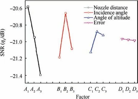
Fig.29 Effect curve of each factor corresponding to F index.

Table 12 Analysis of experimental results.

Table 13 Variance analysis of each factor(Ra).

Table 14 Variance analysis of each factor(F).
Total deviation sum of squares decomposition is obtained by

where STrefers to the total deviation sum of squares decomposition;Sfactorthe sum of square deviation of factor;Serrorthe sum of square deviation of error.
The F statistics is constructed as

The contribution rate of each factorβis calculated as

where Serrorrepresents the sum of square deviation of error;fjand ferepresent the degree of freedom of factor and error,respectively.In this experiment,both the degrees of freedom of factors and errors are 2.
According to the variance analysis of index Ra,

Table 13 shows that the factor A(target distance)has a significant influence on the index Ra,and its contribution rate reaches 55%,followed by the factor B(incidence angle)with a contribution rate of 30%.Meanwhile,the contribution rate of the factor C(elevation angle)is the lowest.
Table 14 shows that factors A(target distance),B(incidence angle),and C(elevation angle)all have extremely significant influence on the experimental index F.The table indicates that the maximum contribution rate of target distance is 62.5%,followed by the incidence angle of 31.2%.Meanwhile,the contribution rate of factor C(elevation angle)is 6.2%.
Tables 13 and 14 show that whether milling force or Rais the experimental index,factor A(target distance d)has the largest influence on the experimental index,followed by factors B(incidence angleβ)and C(elevation angleα).Factor C has the smallest influence among the three factors.
5.3.Analysis of MQL mechanism in milling with nanofluids
In NMQL milling,nanofluid is carried by high-pressure gas,atomized by the nozzle,and injected into the cutting area.High-pressure gas can effectively facilitate nanofluid penetration into the cutting area.Fig.30 shows that a layer of nanofluid will be adsorbed on the milling cutter and workpiece surfaces to form a layer of lubricating oil film.This layer reduces the direct contact between milling cutter and workpiece.The lubrication performance of milling area is considerably improved because of the anti-friction and anti-wear characteristics of nanoparticles.58Cottonseed oil-based Al2O3nanoparticle was used in this experiment as the lubricating oil with added phase.Al2O3nanoparticle has a series of advantages,such as excellent chemical stability,high strength,and high melting point,due to its molecular structure of hexagonal packing.59-61Moreover,this nanoparticle has a spherical structure,which can form a‘‘ball effect”on the surface of the workpiece.Thus,the‘‘ball effect”can reduce the friction between the milling cutter and the workpiece interface,demonstrate good lubrication performance,and improve the surface quality of the workpiece.62-64The content of saturated fatty acid in cottonseed oil is 27.3%,of which palmitic acid is 24.8% and stearic acid is 2.4%.The binding energy between saturated fatty acid and workpiece surface is the largest,and the formed adsorption oil film has high strength,good stability,and good lubrication performance.

Fig.30 Schematic of lubrication in milling interface.
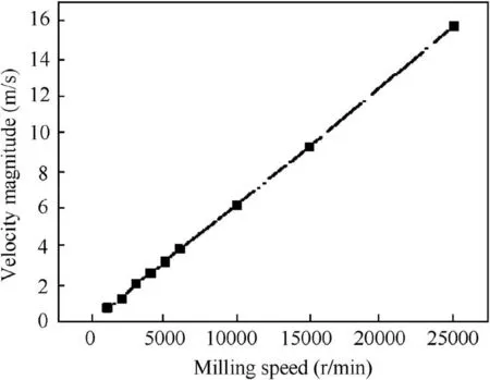
Fig.31 Airflow velocity of flank surface of cutting tool.
Fig.30 shows that during milling,the surface quality of the workpiece is determined by the lubrication performance of the cutter back face and the workpiece surface.However,the poor position of the nozzle will affect the entrance of the nanofluid lubricating oil into the milling area and reduce its lubricating performance due to the influence of the air flow field around the milling cutter.Fig.31 shows the air flow velocity near the flank face of the milling cutter.The air flow velocity increases with the milling cutter speed.When the milling cutter speed is 3000 r/min,the air flow velocity near the rear face of the milling cutter reaches 2.03 m/s.When the milling cutter speed is 25000 r/min,the air flow velocity near the rear face of the milling cutter reaches 15.6 m/s.If the nozzle position is unsatisfactory,the lubricating oil mist will be prevented from entering the milling area and the lubricity will be affected.Proper nozzle position can facilitate the entrance of the lubricating oil mist into the milling area along the air flow direction,improve the utilization rate of lubricating oil,and realize efficient lubrication.
6.Conclusions
The airflow field simulation was conducted through simulation analysis to analyze the influence of milling cutter speed and helical angle and cavity shape on the air flow field around the milling cutter and determine the appropriate nozzle attitude to improve the transmission of lubricating oil droplets.According to the simulated position parameters,the orthogonal experiment of milling in the square cavity of 7050 aluminum alloy was conducted in accordance with the simulated position parameters.The obtained parameters were verified through the analysis of the SNR of milling force and roughness and the observation of chip morphology,and the significance of each parameter of the nozzle position was analyzed.The results are as follows:
(1)According to the analysis of the air flow field around the milling cutter,the air flow velocity and pressure around the milling cutter are related to the milling cutter speed.The air flow velocity and pressure can reach 0.91 m/s and-0.035 Pa(n=1000 r/min),2.03 m/s and-0.4 Pa(n=3000 r/min),3.26 m/s and-0.67 Pa(n=5000 r/min),6.63 m/s and-1.42 Pa(n=10000 r/min),9.60 m/s and-2.12 Pa(n=15000 r/min),and 15.62 m/s and-3.72 Pa(n=25000 r/min).The air flow velocity also increases with the milling speed,which will hinder the transmission of the lubricant if the nozzle position is inappropriate.
(2)The incidence angle of the nozzle is only related to the helix angle of the milling cutter and is approximately the same.The helix angle and cavity shape of the milling cutter do not affect the elevation angle.An elevation angle of 60°-65° is conducive to the transportation of cutting fluid.The shape of the cavity does not affect the velocity and pressure of the flow field.
(3)Factor A(target distance)has a significant effect on the index Ra,which has a contribution rate of 55%,followed by factor B(incidence angle),which has a contribution rate of 30%.All the factors(A,B,and C)have a significant effect on the milling force of the experimental index.The maximum contribution rate of target distance is 62.5%,followed by the incidence angle of 31.2%,while the contribution rate of elevation angle is 6%.
(4)The orthogonal experiment of milling 7050 aluminum alloy square cavity shows that when milling the square cavity(60 mm×60 mm×20 mm),the nozzle position parameters(d=30,β=35°,andα=60°)are appropriate,and the resulting milling force and roughness value are low.The minimum Ra(0.087μm)is reduced by 30.4% from the maximum value(0.125μm).The minimum milling force is 104 N,which is 27.3% lower than the maximum value of the seventh group(d=50,β=15°,andα=70°).
Acknowledgements
This research was financially supported by the National Natural Science Foundation of China(Nos.51975305,51806112 and 51905289),the Major Research Project of Shandong Province of China(Nos.2019GGX104040 and 2019GSF108236),the Shandong Provincial Natural Science Foundation of China(No.ZR2019PEE008),Major Science and Technology Innovation Engineering Projects of Shandong Province of China(No.2019JZZY020111),and Applied Basic Research Youth Project of Qingdao Science and Technology Plan of China(No.19-6-2-63-cg).
 CHINESE JOURNAL OF AERONAUTICS2021年6期
- CHINESE JOURNAL OF AERONAUTICS的其它文章
- Performance evaluation of creep feed grinding ofγ-TiAl intermetallics with electroplated diamond wheels
- Thermomechanical coupling effect on characteristics of oxide film during ultrasonic vibration-assisted ELID grinding ZTA ceramics
- Modeling and experiment of grinding wheel axial profiles based on gear hobs
- Electrochemical machining on blisk channels with a variable feed rate mode
- Framework and development of data-driven physics based model with application in dimensional accuracy prediction in pocket milling
- Electrode design using revolving entity extraction for high-efficiency electric discharge machining of integral shrouded blisk
