A new localization theory of adaptive machining of near-net-shape blades
Neng WAN,Xiogng SHEN,Zhiyong CHANG,*,Zezhong C.CHEN
a Department of Mechanical Engineering,Northwestern Polytechnical University,Xi’an 710072,China
b Department of Mechanical,Industrial and Aerospace Engineering,Concordia University,Montreal,Quebec H3G 1M8,Canada
KEYWORDS
Abstract In the fabrication of aero-engine blades,a great deal is gained when massive material removal is avoided at the end of the process,and as little as possible material is left on the blade billet.Due to the uncertainty of pre-process,the billet shapes are inconsistent.Sometimes,the near-net-shape billet doesn’t cover the blade design surface to be cut.Therefore,blade localization is necessary for these billets before the machining.In conventional localization methods,the design surface’s location focused on guaranteeing enough material to be cut.However,because the to-becut surface is in near-net and free-form shape,it is difficult to find a valid localized surface model to generate the tool path.Different from the localized surface is taken as rigid in previous investigation,it is allowed to deviate from the design surface no more than the tolerance band.In term of this principle,the tolerance band is utilized to promote localization ability.A series of optimization models with different priorities is established to avoid the abandonment expensive blade billet.Finally,with the experiments performed on the near-net-shape blades,the blade localization theory and the promotion of localization ability are verified.
1.Introduction
Aero-engine blades need to be accurately and efficiently produced.Blade materials such as titanium alloys are usually expensive and also difficult to cut.To reduce time and costs,massive material cutting needs to be avoided.In recent years,there has been a trend that the near-net-shape blade is chosen as a blade billet.They can be formed by precision forging or 3-D printing.However,the uncertainty is unavoidable in these processes.As a result,the shapes of the blade billets are different from each other.There is evidence that the reject rate of the precision forging blade is higher than 4% in some workshops.If the blade design model cannot be covered by the near-netshape billet,it cannot be machined directly due to absent material.This is the reason that many workshops choose to enlarge the allowance of the precision forging that is conflict with the target of decreasing to-be-cut material.Thus,blade localization is necessary before the machining.The localized surface is found in the near-net-shape billet to ensure enough material to be cut.Blade localization identifies a surface for generating the tool path.Therefore,localized surfaces must ensure enough to-be-cut material for the machining,and it should satisfy the design tolerance.In further,to maintain the aerodynamic performance requirements,it is as close to their design as is possible.
In conventional researches,the design surface is slightly adjusted to satisfy the above requirements,the shape of the design blade is maintained during the localization.However,tolerance bands and to-be-cut materials leaves a small space for adjusting the design surface.The localization usually fails because the localized surface does not fit inside the billet or beyond the tolerances.To avoid abandonment of expensive near-net-shape billet,it is essential to establish a blade localization theory.
For aerodynamic performance requirements,the machining deviation inside the tolerance band is acceptable.In other words,as the model for toolpath generation,the localized blade is allowed to deviate from the design blade inside the tolerance.In term of this localized blade,the billet can be machined to satisfy the design requirements by a more precise machine tool.Based on this idea,to improve the localization ability,the tolerance band is used to enlarge the solution space of the localization in this paper.In addition,the shape of tobe-machined surface is taken as a flexible body that can be different from the design surface.It helps to enlarge the solution space for finding a valid localized surface.
2.Literature review
The localization of free-form surface parts is a common research topic.Most research focuses on proposing an effective algorithm to quickly transform the design model into the billet.Sun et al.1establish an optimization model for free-form surface parts based on the oriented Euclidean distance,solved by the Lagrange multipliers method.Shen et al.2complete the free-form part localization in two steps.First,the distances between the gravity center and the measured points are minimized for rough fitting.Then the weighted distances from the measured points to the design surface are used to ensure that enough material to be cut is left on the billet.Yan et al.3align the billet surface and the design surface to determine the transformation range in the rough matching.They apply a genetic algorithm in the accuracy matching of the large sculptured surface machining.Chu et al.4addressed the localization of the machined features and the to-be-cut features.In term of the machined features,the to-be-cut features are fit into the billet for machining allowance.In term of difficulty of adding material to its feature,Chatelain and Fortin5,6assigned the weight to the measured points of multi-to-be-cut features,and quickly identified position of material shortage by calculating the oriented Euclidean distance from the measured points to the part.For the freeform surface part machining,localization is more complex than prismatic parts localization.Sun et al.7solve a free-form surface localization optimization by using the SQP method.It is worth noting that the optimization model they propose considers the machining error.The model affirms that the optimized machining allowance should be larger than the possible machining error.Xu,Mehrad et al.8,9address the free-form surface localization based on the similarities in the surface curvatures.Han et al.10use the particle swarm algorithm to obtain a localized free-form surface for the machining.If the initial values are selected properly,the optimization efficiency would be higher compared to the other methods.Wan et al.11proposed a localization method that can obtain the blade edges which smoothly connect with the suction and pressure surfaces.The optimization algorithm is the most important topic in the above research.This algorithm ensures the to-be-cut surface is transformed into the billet.Some research considers the machining error a constraint.However,as a critical constraint for the machining surface,the design tolerance is not introduced into the above optimization model.
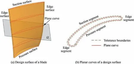
Fig.1 Design surface and its planar curves.

Fig.2 Machining surface and its profile curves.
Some research addresses the distance calculations between the measured points and the design surface.Zhu et al.12,13propose a method to calculate the signed distance from the point to a free-form surface,and they investigate the calculation error.For parts with high-curvature surfaces,Li et al.14propose a new method to improve the accuracy of the distance calculation.Xu et al.15try a subdivision method to compute the distances from the points to a freeform surface.The subdivided segments are represented by using multivariate Bernstein polynomials.He et al.16address a higher-efficiency robustness distance function for the free-form surfaces localization.Flory et al.17extend the distance function to fit the surface and points cloud.This research on distance function calculation supplements free-form surface localization,where optimization efficiency and accuracy are enhanced.However,it does not discuss the characteristics of the blade machining and the design tolerance.In the blade localization,Zhang et al.18propose a unified localization constraint model for free-form surface matching covering unfinished or finished status.The proposed method is applied on blisk machining.Wu et al.19,20localize the cross-section curves of a blisk blade in the billet instead of in the whole volume of the blade.For the localized surface,the machining allowance is required to be within tolerances.
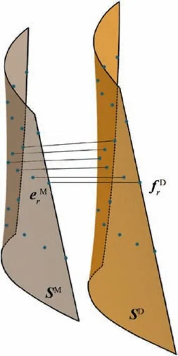
Fig.3 Optimization objective for blade localization.
In summary,conventional localization methods pay insufficient attention to the relationship between free-form shape and tolerance.In these methods,the localized surface is ensured to be inside the billet,and the inevitable machining error is considered.However,the tolerance constraint for the localized surface is ignored.
3.Establishment of blade localization theory
The billet is inspected by the on-machine measurement.The design datum can be matched with the datum of the billet in term of the measurement result.Then,the relative position of the design surface and the billet surface is determined by the match.If the billet surface does not cover the design surface,the localized surface must be generated to preserve the to-be-cut material.Due to the near-net-shape blade billets are different from each other,the inspection and judgement is necessary for each individual billet.
3.1.Definition of design,billet,and machining surfaces
Before explaining the localization theory,it is important to address the definitions of the design,the billet and the machining surfaces.These definitions are discussed in detail in previous work.21There,the machining surface is defined as a rigid surface in the localization and treated as a flexible surface which can deform.
Design surface is the nominal blade surface which is plotted in Fig.1(a).It is constructed by sweeping a group of curves defined on the planesΩi.The planar curves are divided into the pressure,the suction and the edge segments which are plotted in red lines(see Fig.2(b)).It is important to note that the suction and the edge segments are convex,and that the pressure segment is concave.On the planesΩi,the tolerance bands are defined for the blade profiles that are plotted in green dashed lines(see Fig.1(b)).If all profiles inspected on planes Ωiare inside the tolerance bands,the machined blade is a qualified product.
Billet surface is a near-net-shape surface to be cut.In order to reduce error sources from fixtures,on-machine inspection is a trend in precision blade machining.An on-machine probe measures the billet surface with a group of points.These measured points represent the shape of the billet surface in the billet coordinate system.But the billet surfaces are not consistent in shape and they must be measured for each workpiece.
Blade localization slightly transforms the design surface to form a new model.If this model satisfies the design tolerances,the convexity-concavity,and the area inside the billet surface,the localization is valid.This model is called the machining surface(see Fig.2(a)).If this model is not inside the billet surface,or does not meet tolerances,or changes the convexityconcavity of the blade shape,the localization is invalid and the model does not qualify as a machining surface.On planes Ωi,the profile curves of the machining surface plotted in black lines must be inside the tolerance boundaries(see Fig.2(b)).The profile curve divides into suction,pressure,and edge segments.
3.2.A hierarchical blade localization theory
For its near-net-shape blade billet,blade localization slightly changes the location,orientation,and shape of the design surface.To effectively conduct blade localization,a blade localization theory is established in this paper.
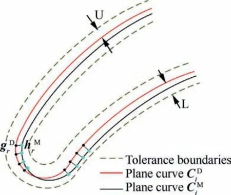
Fig.4 Illustration of condition(2)of blade localization.
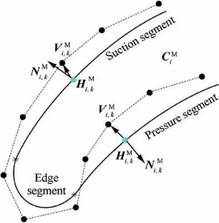
Fig.5 Illustration of condition(3)of blade localization.
3.2.1.Representations in blade localization theory
A group of planar curves are defined on the planesΩi.They are denoted as


The design surface is constructed by sweeping all planar curves.It is denoted as


The machining surface is the localized surface for generating tool path.It is constructed by sweeping a group of curves that are transformed from the planar curves.The machining surface is denoted as


3.2.2.Theorem of the blade localization theory
In the billet coordinate system,if the transformed blade surface is inside the blade billet and its profile curves are within the tolerances,this localization is effective,and the billet is valid.However,if the localization fails,the blade billet would be abandoned.To make the billet valid,the important work is to determine the adjusting parameters of the qualified localization.The blade localization theorem is established as follows.
[Theorem]
If a blade localization is qualified,the following conditions should be met:
Condition(1):A machining surface should be covered by the billet surface,which is expressed as SM⊆ΩB,and the surface shape is expected to be close to the design surface as much as possible.


[Explanation]
During machining,the tool removes the material outside the machining surface in order to generate the blade.If partial surface is out of the billet,there is no to-be-cut material to generate the machined surface.Moreover,if the machining surface are similar with the design surface as much as possible,the aerodynamic performance is maintained as much as possible.
To produce a qualified machined blade,the machining surface should yield the tolerance requirements.Thus,the profile curves on the planesΩishould be within their tolerance band.If the surface is within the billet,however,its profile curves are beyond the tolerances,then the blade is disqualified and cannot be used to generate tool path.
The shape of the blade surface is important to engine aerodynamics,which is controlled by the planar curves.Therefore,on the planar curve,the suction and the edge segments should be convex,and the pressure segment should be concave.That is to say,the profile curves should inherit the convexityconcavity of the planar curves.
[Remark]
In the blade localization,the localized surface’s shape could deviate from design surface’s shape as long as within the tolerances.If the localized blade is machined with enough precision,the profiles of machined surface on planesΩiwould be within the tolerances.The machined blade is qualified.
In the conventional methods,the design surface is transformed into the billet to meet Condition(1).The localization target is to adjust the machining surface in the center of the billet as much as possible.In this theory,the shape of machining surface is allowed to be different from the design surface.The localization target is changed so that the machining surface is close to the design surface as much as possible.Besides,the convexity-concavity of the profile curves should be maintained from the planar curves.Thus,Condition(3)is a new constraint for the localized surface.The design surface of the blade always constructed by skinning method.Thus,there are two ways to change the shape of the design surface to be machining surface.The relative position of the profile curves changes,and even the shape of the profile curves changes.If the former is used,the convexity-concavity of the design surface would be maintained.If the latter is used,the control points adjustment of the profile curves would obey the rules that maintain the convexity-concavity of the design surface.
4.A hierarchical optimization model for blade localization
It is quite difficult to determine a valid blade localization.In order to inherit the design surface shape,the machining surface is adjusted to satisfy all conditions.If there is no result can be obtained,the planar curves of the design surface can be adjusted separately to improve the localization ability.If there is still no result satisfying all conditions,the shape of each planar curve can be modified slightly to construct a valid machining surface.Base on this strategy,a prioritized optimization model of blade localization is formulated.
4.1.Optimization objective model for blade localization


Table 1 Section curve planes(mm).


Scheme 3:For more localization ability to improve,the shapes of planar curves can be changed.Thus,the control points of planar curves are allowed to be translated separately.Ti,kare the translation matrices for each control point Vi,kof the planar curves.Translations are limited in the corresponding planarΩi.The transformed control points are

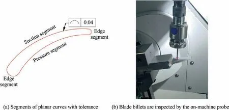
Fig.6 Design blade and blade billet is inspected on machine tool.

Table 2 Measured points of blade billet No.1(mm).
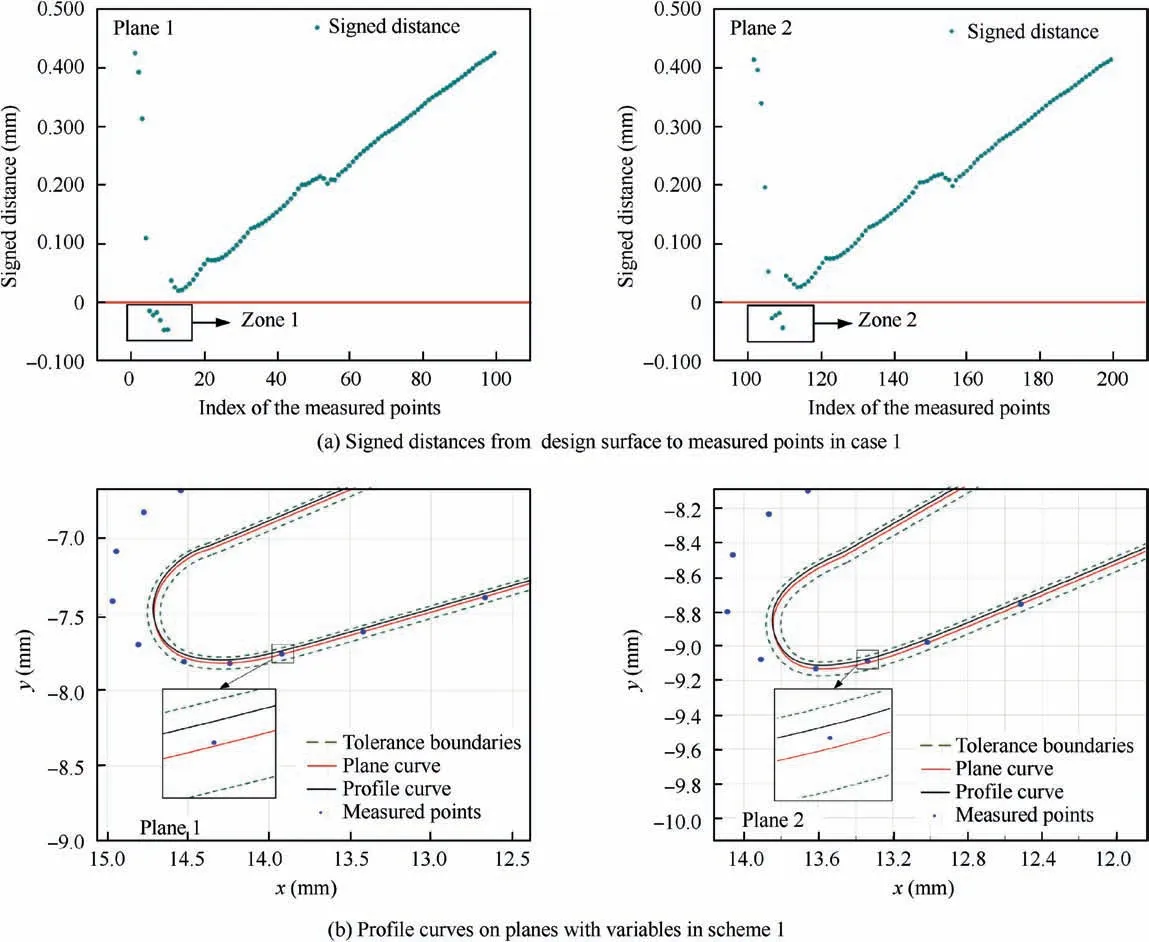
Fig.7 Signed distances in case 1 and profile curves generated by variables in Scheme 1.
And the transformed planar curves are


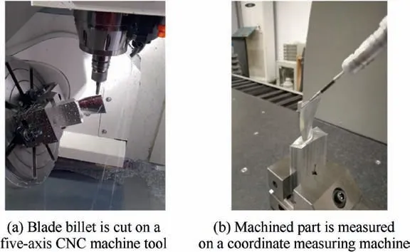
Fig.8 Blade billet and machined part.
4.2.Optimization constraints for the blade localization
4.2.1.Machining allowance constraint

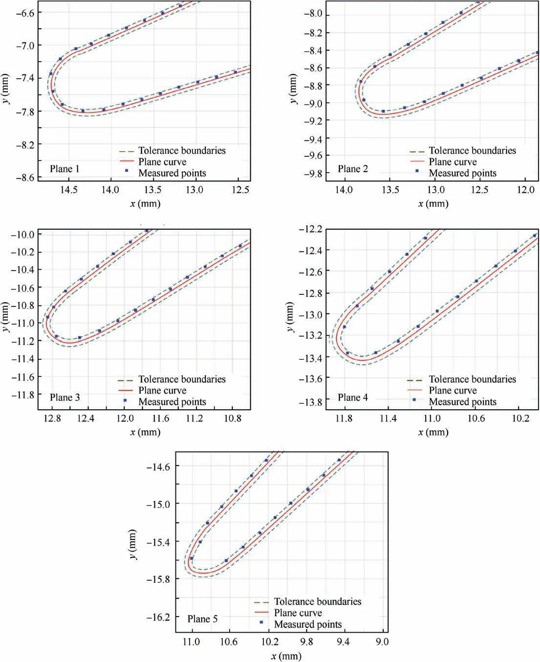
Fig.9 Measurement results on all planes in case 1.

Table 3 Measured points of the billet No.2(mm).
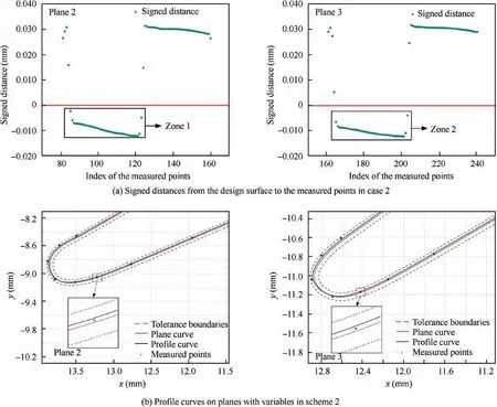
Fig.10 Signed distances in case 2 and profile curves generated by variables in Scheme 2.

Table 4 Optimization results for each planar curves.

and

4.2.3.Curvature constraint

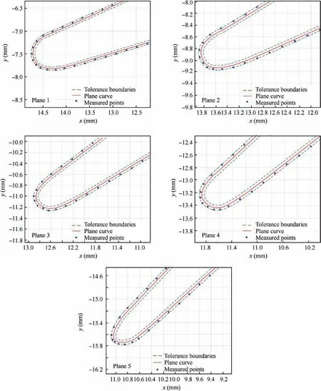
Fig.11 Measurement results on all planes in case 2.

Table 5 Measured points of billet No.3(mm).
The suction and edge segments are convex,thus,the constraints are

The optimization variables in Scheme 1 provide fastest localization which is first applied.If the machining surface yielded all constraints cannot be found,the optimization variables in Scheme 2 could be substituted into the localization optimization.More time is consumed with more variables in optimization,however,the localization ability is promoted.If optimization result still cannot be determined,the optimization variables in Scheme 3 are finally applied.Similarly,more time is consumed in the optimization.However,the localization ability is promoted with further enlarged variable space.
5.Applications
The proposed localization theory is applied on three near-netshape blade billets.A blade design surface with the planar curves on the planesΩi.The heights of the planesΩiare listed in Table 1.The tolerances are±0.040 mm which are defined on these planes(see Fig.6(a)).The datum of inspection and machining is defined on the finished machined pedestal which is clamped on a vise.The alignment error is decreased to least by a dial indicator.In further,to reduce the error sources in the inspection,the blade billets are inspected on a five-axis CNC machine tool with an on-machine probe(see Fig.6(b))before the localization.A touch probe from HEXAGON company is selected and its repeatability at probing from one direction is no more than 1μm.Then,the inspection result is imported into a computer and is matched with the blade design.
Case 1.The measured points of billet NO.1 are partially listed in Table 2.When the design datum is matched with the machining datum,the relative position of the billet surface and the design surface are determined.The signed distances from the design surface to the measured points are calculated.The signed distances on the planes 1 and the plane 2 are plotted in Fig.7(a).The red line represents zero distance.Obviously,the negative distances indicate that the billet surface cannot cover the design surface(zone 1 and 2 in Fig.7(a)).Therefore,the blade localization is necessary before the machining.
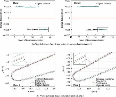
Fig.12 Signed distances in case 3 and the profile curves generated by variables in Scheme 3.
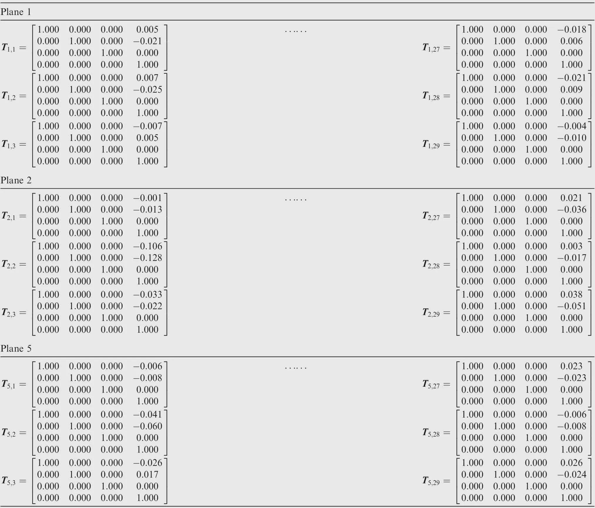
Table 6 Optimization results for the control points of planar curves(mm).
The machining surface is determined by the transformed planar curves with R and T.The profile curves of the machining surface on the absent material planes are plotted(see Fig.7(b)).On all planes,the signed distances from the machining surface to the measured points are positive that means there is enough material on the machining surface.Meanwhile,it could be observed that the profile curves are inside the tolerance bands.This case has no difference with present localization state.Many optimization algorithms can be used to find a local optimal solution for the localization.
The blade billet is machined in term of optimized machining surface(see Fig.8(a)).And then,the machined blade is measured on a coordinate measuring machine(see Fig.8(b)).The measured points are inside the tolerances(see Fig.9).The average error is 0.006 mm that means the cut blade in this case satisfies the tolerance requirement.It is a lucky case that can be solved by the least optimization variables.
Case 2.The No.2 billet is inspected,and the measured points are listed in Table 3.The signed distances on the planes are calculated.The absent material occurs on the plane 2 and plane 3(see zone 1 and 2 in Fig.10(a)).Thus,the blade localization is also necessary.
The optimization variables in Scheme 1 are firstly applied.However,the machining surface satisfied all constraints cannot be found.Then,the Scheme 2 are implemented subsequently.The localization with 20 variables is completed in 110 s.Each planar curve has its own transformation which is listed in Table 4.
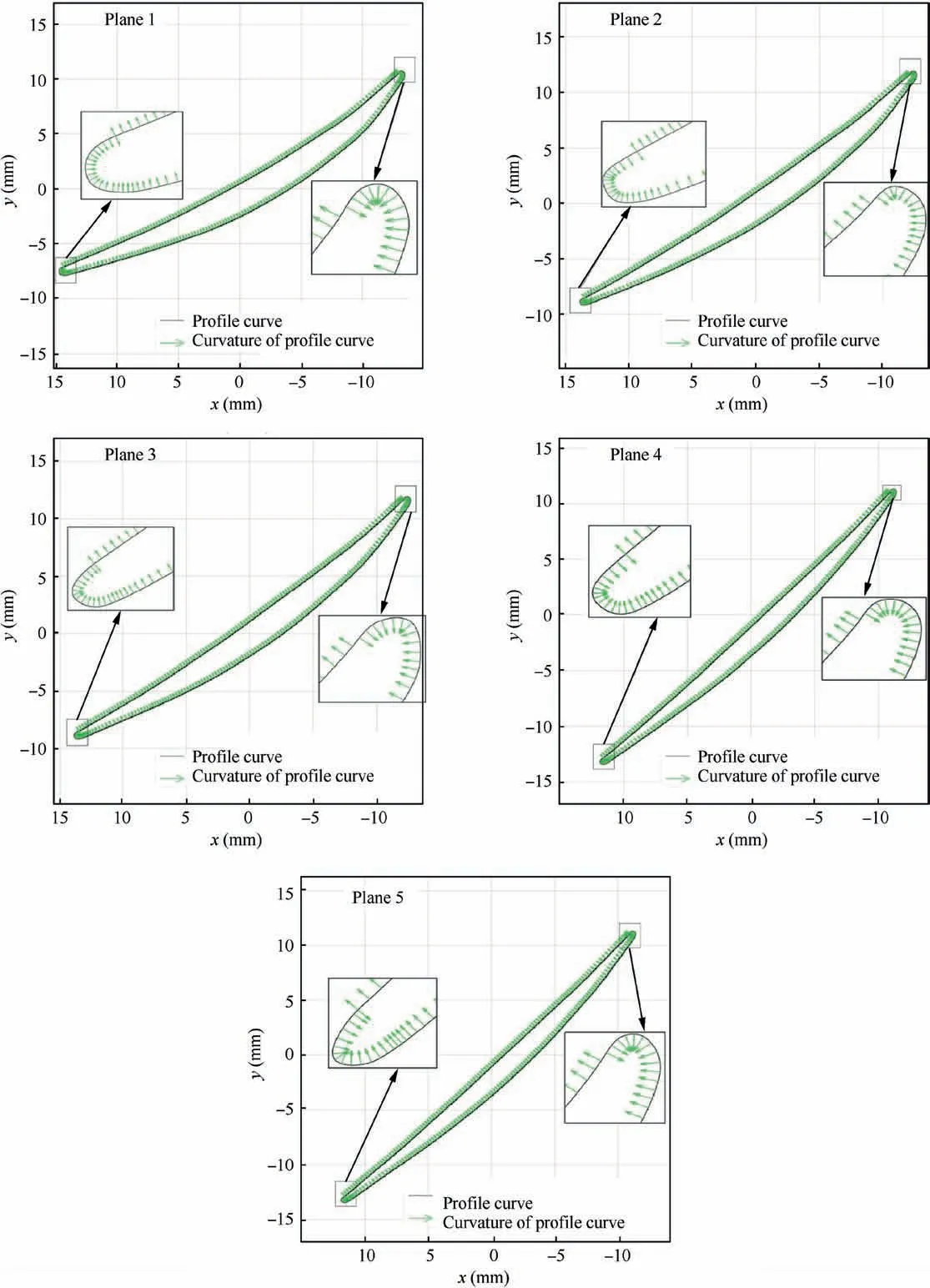
Fig.13 Curvatures of optimized profile curves in case 3.
The profile curves of the optimized machining surface on the plane 2 and the plane 3 are plotted(see Fig.10(b)).The profile curves of the machining surface are inside the tolerance bands.Moreover,the signed distances from the machining surface to the measured points on all planes are positive.Thus,the machining allowance constraint is satisfied for the machining surface.The method in this case has a distinct difference with present localization state.The relative positions of the profile curves have changed that caused the machining surface is different from the design surface.Of course,the optimization variables increased compare to the previous localization.The time consumption on the localization becomes larger in this case.
The blade billet is machined in term of the machining surface obtained by the Scheme 2,and the machined blade is measured also.The measurement results are plotted(see Fig.11).The average error is 0.008 mm that the machined surface is still not beyond the tolerance.It means the scrapped blade billet that cannot be saved by Scheme 1 is saved by Scheme 2.Although it took more time,but it is worthy for expensive parts.
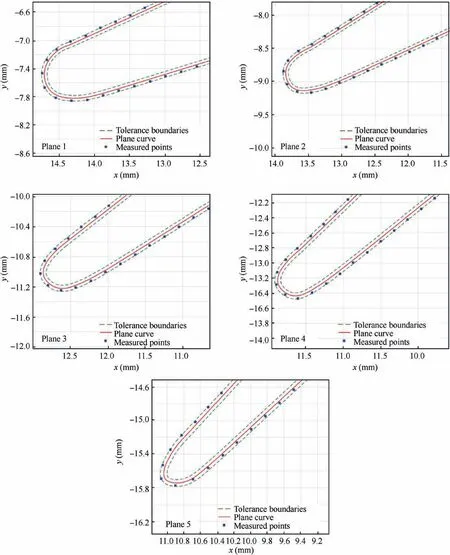
Fig.14 Measurement results on all planes in case 3.
Case 3.The No.3 billet is inspected and the measured points are listed in Table 5.The material is absent on the plane 1 and the plane 2(zone 1 and 2 in Fig.12(a)).The blade billet cannot cover the design surface.Thus,the localization is necessary in this case.
The Schemes 1 and 2 are utilized to find the solution of the machining surface sequentially.However,no optimization solution can be found.Thus,the Scheme 3 are applied to find a machining surface.The localization with 290 translation variables cost 1320 seconds to obtain a machining surface.The optimization results are listed in Table 6.
After localization,the profile curves of the optimized machining surface on the plane 1 and the plane 2 are plotted(see Fig.12(b)).All signed distances from the machining surface to the measured points are positive.That is to say,there is enough to-be-cut material on the blade billet.
On each plane,the signed distances from the profile curves to the planar curves are less than the tolerance that means the tolerance constraint is satisfied.Moreover,the curvatures of each profile curve segments are plotted(see Fig.13).The pressure segment is concave,and the suction and the edge segments are convex.The convexity-concavity of the curvature is satisfied for all profile curves.The method in this case also has a distinct difference with present localization state.Similar with the case 2,the machining surface is different from the design surface.However,the profile curves have been changed from the design curves that provide a larger solution space.
The No.3 blade billet is machined in term of the localized machining surface,and the machined blade is measured also.The measurement results are plotted(see Fig.14).The average error of the machined surface is 0.007 mm that is still not beyond the tolerance.It proves that the optimized blade can be machined.Obviously,it taken the most time for the localization.Whereas,it still has to be done for saving the expensive parts.
From above cases,it is proved that the blade localization theory is qualified for near-net-shape blade.With the optimization variables increasing,the time consumption of the blade localization would be enlarged.However,the localization ability would be promoted to save the blade billet to be abandoned.
6.Conclusions
The near-net-shape billet is a trend for precision machining.To increase production qualifications,a blade localization theory for the near-net-shape blade is here addressed.This theory proposes a design surface position adjustment that differs from what is found in the conventional method.The shape of the design surface is allowed to be slightly changed in its tolerance band.As a result,the ability of finding out a valid localized surface is enhanced with more optimization variables.The shape of the localized blade surface is as close to the shape of the design surface as is possible.Differently from only ensuring enough material to be cut,the tolerance and the curvature requirements of blade design are inherited in the blade localization.In summary,the key novel is the blade design is regarded as a deformable body but not a rigid body.Base on this principle,the localization theory is expanded.A hierarchical localization model is proposed in which the optimization variables get more and more complicated to obtain the bigger solution space of the localization.In addition,the proposed localization theory can be generalized to the parts with the free-form surface such as impellers or blisks.The localization is necessary to be applied on part repair,3D printed parts,and so on.On the other hand,the skinning method is common in blade design.Thus,the skinning surface is discussed in this paper.In fact,the theory can be generalized to the free-from surface constructed by other method.The core idea is not changed that the machining surface can be different from the design surface.To popularize the proposed theory,the free-form surface is required to be a parametric surface.By adjusting the control points of the parametric surface,it easy to establish an optimization model for the localization.
After the proposed blade localization,the tolerance band would be occupied by the machining surface.In some areas,the tolerance band would be narrower than the original.Because the tolerance band impacts the tool path generation,it is worthwhile to study the compensation of tool path generation in future research.
Acknowledgements
The financial support of this work from the National Natural Science Foundations of China(No.51775445),the Fundamental Research Funds for the Central Universities of China(No.31020190503008),the Xi’an Science and Technology Project(No.201805042YD20CG26(9))and The Project Supported by Natural Science Basic Research Plan in Shaanxi Province of China(No.2019JM-349)are thankfully acknowledged.
 CHINESE JOURNAL OF AERONAUTICS2021年6期
- CHINESE JOURNAL OF AERONAUTICS的其它文章
- Performance evaluation of creep feed grinding ofγ-TiAl intermetallics with electroplated diamond wheels
- Thermomechanical coupling effect on characteristics of oxide film during ultrasonic vibration-assisted ELID grinding ZTA ceramics
- Modeling and experiment of grinding wheel axial profiles based on gear hobs
- Electrochemical machining on blisk channels with a variable feed rate mode
- Framework and development of data-driven physics based model with application in dimensional accuracy prediction in pocket milling
- Electrode design using revolving entity extraction for high-efficiency electric discharge machining of integral shrouded blisk
