Effect of bent inlet pipe on the flow instability behavior of centrifugal compressors
Zhenzhong SUN, Botong WANG, Xinqin ZHENG,c,
Tomoki KAWAKUBOb, Hideaki TAMAKIb, Ryuusuke NUMAKURAb
a Department of Aerodynamics and Thermodynamics, Institute for Aero Engine, Tsinghua University, Beijing 100084, China
b Corporate Research & Development, IHI Corporation, Yokohama 235-8501, Japan
c State Key Laboratory of Automotive Safety and Energy, School of Vehicle and Mobility, Tsinghua University, Beijing 100084,China
KEYWORDS Bent pipe;Centrifugal compressor;Flow field;Flow instability;Surge boundary
Abstract Bent inlet pipes are often used in centrifugal compressors due to limited installation space, and an understanding of the effect on compressor stability is essential for safety and durability. This paper firstly investigates flow instability behaviors in two compressors, one with a straight inlet pipe and the other with an S-shaped bent pipe.In detail,it analyzes the resulting flow fields, instability evolution paths and surge boundaries. The results show that the S-shaped pipe obviously affects the flow field at high mass flow rates,while reverse flow mainly influences the flow field at low mass flow rates. Reverse flow first occurs at certain flow passages with a high pressure difference that is predominantly decided by the volute rather than the S-shaped bent pipe.In addition,centrifugal compressors can tolerate reverse flow to some extent so that surge would not occur immediately if reverse flow occurs unless the reverse flow region extends circumferentially and radially to a sufficiently large size.Since the S-shaped pipe is not dominant in the creation and extension of reverse flow,it does not exacerbate the stability of the central compressor to a great extent.Last but not least, the S-shaped pipe is noted to delay the occurrence of surge at 90% rotating speed,which suggests the possibility of improving compressor stability with bent inlet pipes. This result differs from the conventional understanding that inlet distortion usually deteriorates compressor stability and emphasizes the particularity of centrifugal compressors.
1. Introduction
Due to the advantages in efficiency, maintenance and compactness,centrifugal compressors are widely used in industry,1such as turbochargers,air conditioning systems2and small gas turbine engines.3However, one of the dominant bottlenecks for compressor application is flow instability,4such as surge,stall or rotating instability. Surge is related to the entire compression system and is accompanied by grating noises, vibrations and oscillations of the annulus-averaged flow in the system.5,6In contrast, stall is associated with flow separation and is more of a local behavior, and the time-averaged mass flow rate remains constant when stall occurs.7,8Xue and Wang9recently reported that the degree of stall can be well identified by a quantitative indicator extracted from the chaotic recursive graph of the reconstructed dynamic signals.Rotating instability is also a local phenomenon that is correlated with the formation and movement of vortices near the leading edge of the compressor impeller(or rotor),10and there is often a broadband characteristic to its frequency spectrum.11-13
Many factors affect flow instability in a centrifugal compressor, such as geometric design, systematic characteristics,and flow conditions. Flow field distortion is a common factor that is closely related to flow instability, and it can be caused by the volute, nonuniform tip clearance, and bend flow passages. Since installation space is often limited, it is common to use a bent pipe upstream of the centrifugal compressor that will generate vortices and distort the downstream flow field.14Therefore, investigating the influence of a bent pipe on compressor performance, especially flow instability behavior, is of significant importance.
The distorted flow fields caused by bent pipes have been experimentally investigated by Kim et al.15; they found that the distortion intensity decreases and dissipates along the flow direction quickly and noted that the bend radius of the pipe greatly influences the downstream flow field. Kim et al. compared centrifugal compressor efficiency with two different inlet configurations,16one of which was straight with a constant cross-sectional area and the other a 90°curved pipe with a nozzle shape. A similar comparison was carried out by Li et al.17The results show that the choke mass flow rate decreases when a bent pipe is used, and bent pipe distortion is found to influence the unsteady pressure pulsation in the diffuser. Performance degradation due to bent pipe-induced distortion was reported by Wang et al.18They also concluded that both the volute and the bent inlet pipe influence the diffuser flow field.In addition, Yang et al.19investigated the clocking effects related to the bent inlet pipe and the volute, and the results show that the total pressure ratio and mass flow rate were influenced. Recently, a more detailed clocking effect study was performed by Zhao et al.,20who noted that adjusting the circumferential orientation of the bent inlet pipe could cause an obvious deviation in the compressor aerodynamic efficiency and that the compressor operating range was related to the total pressure deficit and the vortices induced by the bent inlet pipe.
Most research works focus on stage performance, such as efficiency,the choke mass flow rate,or the flow field.However,one of the greatest challenges for centrifugal compressor application is the stability limitation. Unfortunately, only a few public references have discussed the influence of the bent inlet pipe on compressor stability. One such study was performed by Zhang et al.,21who recently found that the bent inlet pipe does not influence the circumferential position of the onset of stall inception and that the volute has a larger influence on the compressor stall process.In fact,distortions in the flow field obviously influence compressor stability, especially for axial compressors. Many studies22-26have been conducted to discuss and analyze the negative effects of inlet distortions on axial compressor stability and stabilization with inlet distortions. For centrifugal compressors, the volute’s influence on stability is more often discussed.Works by Zheng et al.27,28show that volute-induced distortions could obviously narrow the stable flow range of centrifugal compressors.
In summary, previous works have shown that inlet distortions could greatly exacerbate the stability of axial compressors and that the volute greatly harms the stability of centrifugal compressors.However,for bent inlet pipes installed upstream of centrifugal compressors, most discussions focus on the performance influences, and few investigations have been undertaken on stability influences.In this paper,unsteady simulations are carried out with a turbocharger centrifugal compressor to investigate the influence of an S-shaped inlet pipe on flow field and flow instability, and experiments are then performed to evaluate variations in the surge boundary.
2. Numerical setup and validation
The centrifugal compressor investigated in this paper is used in a turbocharger and was introduced in Ref.10. Its impeller has six main blades and six splitter blades, and the impeller is backswept with a backsweep angle of 38°. A vaneless diffuser with a width of 2.65 mm is used, and downstream of the diffuser is a volute that will induce distortion.More detailed geometric specifications are listed in Table 1. To investigate the influence of inlet distortion, two inlet pipes are studied in this paper: one is an S-shaped pipe, and the compressor with this pipe is termed ‘‘S-Pipe”; the other is a conventional straight inlet pipe, and the related compressor is termed ‘‘Straight Pipe”. Geometric details of these two inlet pipes are shown in Fig. 1.
The entire simulation domain in this paper not only contains the compressor itself but also the inlet pipes and outlet pipe (see the example of the S-Pipe in Fig. 2), which allows the simulation model to consider the influence of inlet distortions induced by the inlet pipes.The compressor contains three components,the impeller,the vaneless diffuser and the volute,and finished meshes of these three components are illustrated in Fig. 3. The fluid domain of the impeller and the diffuser is spatially discretized by structured meshes with the commercial software ANSYS TurboGrid. However, the fluid domain of the volute is spatially discretized by an unstructured mesh because of its complex geometry, and this unstructured mesh is generated with the commercial software ANSYS ICEM.Additionally, the fluid domains of inlet pipes and outlet pipe are spatially discretized by structured meshes with the commercial software ANSYS ICEM. The finished mesh of the entire simulation model contains eight million elements.
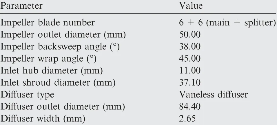
Table 1 Geometric parameters of compressor.10
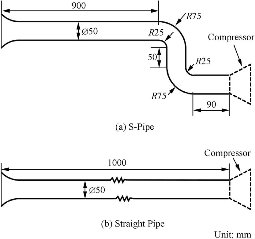
Fig.1 Geometric details of two inlet pipes installed upstream of compressor.
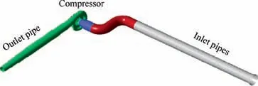
Fig.2 Entire simulation domain for investigated compressor‘‘SPipe”.
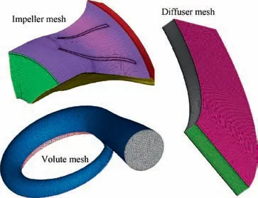
Fig. 3 Finished meshes of compressor subcomponents.
Unsteady simulation is used as the main tool to investigate the unsteady flow phenomenon with the commercial software ANSYS CFX,and the boundary conditions are set as follows:the total temperature, total pressure and flow direction are imposed as the inlet boundary condition, while static pressure is imposed as the outlet condition. All solid walls are set as nonslip and adiabatic, and a two-equation SST (Shear Stress Transport)turbulence model is selected for turbulence closure.The interface model between the rotating part (impeller) and stationary parts is a sliding mesh. For every time step, the impeller rotates 0.5°; in other words, there are 720 time steps for every rotor revolution. To obtain the initial conditions for the unsteady simulations, steady simulations are also carried out,and the steady numerical results are also used to validate the numerical model by comparing them with the experimental results. The setup of the steady simulations is quite similar to that of the unsteady simulations; the differences are as follows:(A)the interface model between the rotating and stationary parts is set to‘‘Frozen Rotor”for the steady simulations,and(B)the mass flow rate is imposed as the outlet boundary condition when the compressor operates at near surge conditions for the steady simulations. Since the turbocharger centrifugal compressor often operates at corrected rotating speed (Ncor) of 1.6×10⁵r/min when the pressure ratio is approximately 2.0, the numerical simulations are carried at this rotating speed.
To validate the accuracy of the numerical model, the performances predicted by the numerical model and the experiments are compared, as shown in Fig. 4. For both the Straight Pipe and the S-Pipe,the predicted total pressure ratio characteristics by the numerical simulations agree well with the experimental results, which provides direct evidence for the accuracy of the numerical model. Fig. 4 also shows the points where the unsteady simulations are carried out. As marked in Fig. 4, the high mass flow rate condition (HM, 70% of the experimental choke mass flow rate)and the low mass flow rate condition(LM,50%of the experimental choke mass flow rate)at 1.6×10⁵r/min were investigated with unsteady simulations.
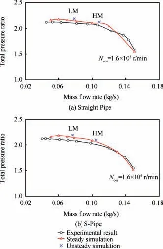
Fig.4 Performances predicted by numerical simulations (steady& unsteady) and experiments.
3. Flow instability inception and mechanism
As mentioned above, numerical investigations are carried out at a rotating speed of 1.6×10⁵r/min. This section will first analyze flow fields and distortions for both S-Pipe and Straight Pipe at different mass flow rates(HM& LM). Then,the transient throttling process of the S-Pipe will be investigated to detect the initiation of reverse flow. Finally, the relationship between distortion and the inception of reverse flow will be analyzed.
3.1. Characteristics of distorted flow fields and distortions related to volute and S-Pipe
The volute is used in both the Straight Pipe and S-Pipe, and induces heavy distortions because of its nonaxisymmetric geometry. Meanwhile, the bent inlet pipe will also induce distortions and influence the flow field at the impeller inlet.Since the influence of the S-Pipe is relatively small at the diffuser and volute in this study, the flow field comparison between the Straight Pipe and S-Pipe will focus on the impeller inlet position.
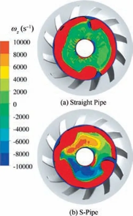
Fig. 5 Comparison of axial vorticity contours at impeller inlet between Straight Pipe and S-Pipe (LM condition).
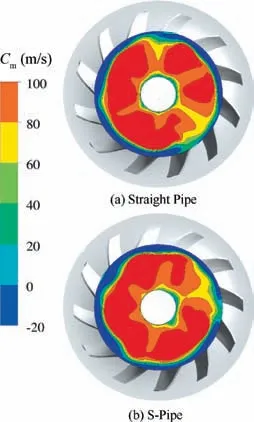
Fig. 6 Comparison of streamwise velocity contours at impeller inlet between Straight Pipe and S-Pipe (LM condition).
Shown in Figs. 5 and 6 are comparisons of axial vorticity(ωz) contours and streamwise velocity (Cm) contours, respectively. The comparisons are carried out at the same crosssection of the inlet pipe, and the cross-section is located at 5% of the impeller outlet diameter upstream of the impeller leading edge.In addition,all the contours are snapshot results of the unsteady simulations at the LM condition.According to Fig.5,for both the Straight Pipe and S-Pipe,the center region is surrounded by a ring with positive axial vorticity, which is caused by the reverse flow. The streamwise velocity contours shown in Fig. 6 indicate that the region near the casing is full of reverse flows (negative streamwise velocity region) regardless of using a straight pipe or an S-shaped pipe. Since these reverse flows come from the rotational impeller, they must have a tangential velocity imposed by the impeller blades, so they have a positive axial vorticity (in the same direction of impeller rotation). Additionally, for both the Straight Pipe and S-Pipe, the reverse flow regions are not circumferentially axisymmetric, which is caused by distortion from the volute.
Under LM conditions, the difference in the axial vorticity contours between the Straight Pipe and S-Pipe lies in the center region of the inlet pipe cross-section.In this region,there is no vorticity for the Straight Pipe, while a pair of counterrotating vortices appears for the S-Pipe.According to Fig.6,the distribution of streamwise velocity is distorted since the center region is inlaid with low and high streamwise velocity areas.This distribution is also different between the Straight Pipe and S-Pipe. Considering that the only geometric difference is the inlet pipes upstream of the compressor—a straight pipe is used for Straight Pipe, while an S-shaped bent pipe is used for S-Pipe—the pair of vortices, as well as the difference in the distribution of streamwise velocity, must be caused by the S-shaped inlet pipe.
Based on the discussions above, in summary, when a centrifugal compressor with an S-shaped inlet pipe operates under LM conditions, the flow field at the impeller inlet is predominantly influenced by the reverse flow near the casing regions,while in the center regions, the flow field is influenced by the inlet distortions induced by the S-shaped pipe. The axial vorticity contours in the HM condition are illustrated in Fig. 7.Obviously, for the Straight Pipe, there is no vorticity at the impeller inlet,indicating that no vortex is formed here.In contrast, for the S-Pipe, the positive and negative axial vorticity regions clearly show the structure of the pair of counterrotating vortices.These results are quite similar to those at the center part of the cross-section under LM conditions,and they are absolutely caused by the S-shaped inlet pipe. Compared with the results obtained under LM conditions, the strengths of the vortices are much stronger under HM conditions, and no reverse flow occurs near the casing regions.
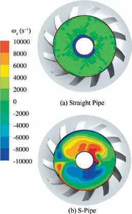
Fig. 7 Axial vorticity contours of Straight Pipe and S-Pipe at impeller inlet (HM condition).
For the S-Pipe, it can be seen that the flow field at the impeller inlet is predominantly decided by the inlet distortion in the HM condition, while the reverse flow plays a more important role in the LM condition, especially near the casing regions. One of the reasons for this is that the strength of the distortion induced by the S-shaped inlet pipe decreases as the mass flow rate decreases (from HM to LM), which can be proved by simulating the flow passing through an S-shaped pipe. As shown in Fig. 8, the flow fields downstream of the S-shaped pipe are compared at two mass flow rates (HM &LM). The axial vorticity distribution clearly shows the pair of counterrotating vortices structures, which provides direct evidence that the pair of structures is caused by the S-shaped pipe. The most important result of this analysis is that when the mass flow rate changes from HM to LM,the total pressure flow field becomes less distorted, and the total pressure loss is also reduced since the low total pressure region is decreased.In addition,the axial vorticity also becomes much weaker at LM compared with HM. In this way, it shows that the strength of the vorticity and the amplitude of the distortion caused by the S-shaped pipe decrease with mass flow rate, which explains why the inlet distortion is not the dominant reason for the distorted flow field at LM;instead,the flow field is predominantly decided by the reverse flow.
3.2. Instability development and relationship with distortions
When the compressor with the S-shaped inlet pipe operates under HM conditions, the flow field at the impeller inlet is decided by the inlet distortion, and no reverse flow occurs.Under LM conditions,the reverse flow fills the annular region near the casing, which is the dominant factor that determines the flow field.Additionally,reverse flow is an extremely important instability indicator of compressors. For the purpose of clarifying how the reverse flow appears and develops and understanding the relationship between the distortion and the inception of reverse flow, it is necessary to investigate the evolution process from HM to LM. To do so, another unsteady simulation is carried out at a rotating speed of 1.6×10⁵r/min. As shown in Fig. 9, the outlet static pressure imposed at the outlet boundary is no longer a constant value but rather increases with time. This setting could represent the throttling process in compressors,allowing the compressor to operate from HM to LM and at even smaller mass flow rates; in this way, the evolution of the instability in the compressor could be obtained.
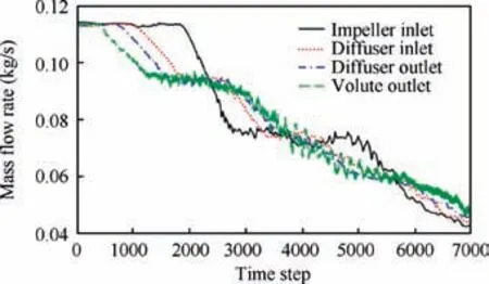
Fig. 10 Time history of mass flow rate at different streamwise positions during instability evolution process.
The inlet pipe of the simulated compressor is an S-shaped pipe. Therefore, the influence of both the volute distortion and the inlet distortion are considered together, making the results more universal. Under the time-dependent outlet static pressure boundary condition, mass flow rates at different streamwise positions are illustrated in Fig. 10. As time and the imposed outlet static pressure increase,the mass flow rates at all selected streamwise positions decrease,and the compressor gradually operates towards the unstable condition.Another interesting phenomenon is the time-lag effect between these mass flow rates.As shown in Fig.10,the mass flow at the volute outlet begins to decrease first, and then the mass flow rates at the diffuser outlet, the diffuser inlet and the impeller inlet decrease successively. In fact, this phenomenon reflects the propagation of the static pressure change. The pressure change at the outlet boundary condition propagates upstream as a pressure wave, which goes through different streamwise positions successively and increases the local static pressure and results in a decrease in the mass flow rate.The static pressure changes at different streamwise positions during the evolution of instability is illustrated in Fig. 11, which shows the static pressures normalized by their initial values (the value at the first time step). This clearly presents the pressure propagation along the streamwise direction. The static pressure at the volute outlet first increases following the pressure rise at the outlet boundary condition, and then the static pressures at the different positions begin to increase one by one. It can be noticed from Fig. 11 that it takes a much longer time for the pressure to propagate through the outlet pipe and the volute since the time lag is longer in these two regions.In contrast,the static pressure at the diffuser outlet,the diffuser inlet and the impeller inlet increases almost simultaneously,indicating that the pressure propagation at the impeller region and diffuser region is much faster. In addition, Fig. 11 shows that the static pressure behavior at the impeller inlet is much different from those at other positions: during the instability process, the static pressure at all other positions continuously increases while the static pressure at the impeller inlet begins to decrease and fluctuate after increasing for a while. This is because reverse flow occurs at the impeller inlet, which will be discussed and analyzed below.
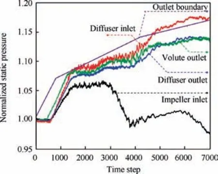
Fig. 11 Time history of static pressure at different streamwise positions during instability evolution process.
The occurrence of reverse flow is a key indicator of flow instability.Considering that reverse flow damages the structure of the pair of counterrotating vortices and forms a positive axial vorticity region near the casing, the axial vorticity contour is used as an indicator of the occurrence of reverse flows in this paper. Five time steps during the evolution process are selected,and the axial vorticity distribution at these time steps is shown in Fig.12 to investigate the inception of reverse flow.These time steps are named T1to T5, and the mass flow rate decreases successively.As the mass flow rate decreases,reverse flow first appears in the casing region within the circumferential ranges of 0°-120° and 340°-360° (time steps T2& T3). To illustrate this point more clearly, Fig. 13 presents the circumferential distributions of the streamwise velocity at 97% span.According to the results at time step T2,the reverse flow region could be easily distinguished and agrees well with the results shown in Fig. 12.
After the initiation of reverse flow, Fig. 12 shows that the reverse flow region extends circumferentially to the entire annulus, and then the outer regions near the casing at the impeller inlet are full of reverse flows (time step T4in Fig. 12 and Fig.13).The mass flow rate at time step T4is close to that of the LM condition and is far from the surge boundary. This reveals that the centrifugal compressor could tolerate the occurrence of reverse flow to some extent and that surge would not immediately occur when revere flow appears. In fact,because most of the pressure rise in a centrifugal compressor is achieved by centrifugal force, only when the reverse flow region is large enough will the centrifugal compressor lose its ability to increase pressure and go into surge. A further decrease in the mass flow rate of the compressor leads to a strengthening of the reverse flow and the reverse flow region extends towards the inner region.The strengthening and extension of the reverse flow damages the structure of the pair of vortices, and it eventually leads to most of the flow passage cross-section to fill with reverse flow (time step T5).
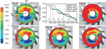
Fig. 12 Axial vorticity distributions at impeller inlet at different time steps (T1-T5 gradually approaching flow instability).
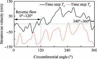
Fig. 13 Circumferential distribution of streamwise velocity at 97% span of impeller inlet at time steps T2 & T4.
According to Figs.11 and 12 together,it is noted that when the reverse flow extends circumferentially to the entire annulus at the impeller inlet, the static pressure at the impeller inlet happens to decrease at the same time with continuously increases of those at other streamwise positions. Therefore,the heavy reverse flow is the main reason why the static pressure behavior at the impeller inlet differs from those at other streamwise positions. The reverse flow significantly influences the flow field and the performance of the impeller as it grows to fill the entire cross-section of the impeller inlet,and the pressure propagation within the impeller is also disturbed.In addition, the time history of static pressure shown in Fig. 11 also indicates that the impeller may suffer heavier flow instability compared with the other components.
The discussion above reveals that reverse flow first occurs at certain local circumferential regions at the impeller inlet,which suggests that reverse flow should be related to the circumferential distortion at the impeller inlet and outlet. The real physics of reverse flow is that the flow lacks sufficient momentum to overcome the pressure gradient,so it is reasonable to consider the pressure difference between the impeller inlet and outlet;it is most likely that the reverse flow occurs first in the region where the pressure difference is high. Before investigating the pressure difference between the impeller inlet and outlet, the static pressure distribution at the impeller inlet and outlet should be discussed first. The time-averaged unsteady simulation results are analyzed here, and the unsteady calculations are carried out at the HM condition with the S-Pipe(HM represents the condition before reverse flow occurs, which is appropriate for studying the inducement of reverse flow).Fig. 14 shows a comparison between static pressure distributions along the circumferential direction for the impeller inlet and the impeller outlet;obviously,none of the pressures is circumferentially uniform,and both possibly to contribute to the occurrence of reverse flow. In addition, it can be seen that the two curves have quite similar shapes but with different phases and that the fluctuation range of the static pressure at the impeller outlet is much larger than that at the impeller inlet.
The fluid enters one flow passage at the impeller inlet and leaves from the same flow passage at the impeller outlet, so it is more appropriate to consider the same flow passage rather than the same circumferential angle when discussing the pressure difference.Thus,the impeller wrap angle and the rotating effect of the impeller should be considered together. At a certain time t1, the static pressure at the impeller outlet propagates through a flow passage, and it takes some time period δtto arrive at the impeller inlet and affect the flow there.During this propagation process, the pressure signal also travels over a circumferential distance φp, which should be the sum of the impeller rotating angle φrand the wrap angle φw.A simplified geometric model, as shown in Fig. 15, could be used to evaluate the length of the impeller flow passage l,allowing for the calculation of the impeller rotating angle φr. As shown in Fig. 15, the radius of the impeller inlet and outlet, together with the wrap angle, determine a triangle, and the length of the side corresponding to the wrap angle is used to represent the approximate length of the impeller flow passage. Geometrically, we have,
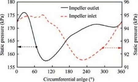
Fig. 14 Circumferential distribution of static pressure at impeller inlet and outlet (time-averaged results of HM).
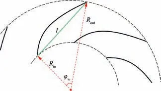
Fig. 15 Simplified geometric model for evaluating length of impeller flow passage.

According to the geometric parameters listed in Table 1,the radius of the impeller inlet and outlet could be taken as 12 mm and 25 mm, respectively, and the impeller wrap angle is 45°.Then,
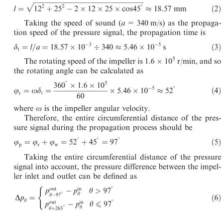

where θ is the circumferential angle, pinand poutis the static pressure at impeller outlet and impeller inlet, respectively,and subscripts represent the circumferential angle.
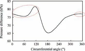
Fig. 16 Circumferential distribution of pressure difference between impeller inlet and outlet (HM condition of S-Pipe).
According to the definition shown in Eq. (6) and the data shown in Fig. 14, the pressure difference between the impeller inlet and outlet is calculated and is shown in Fig. 16. Regions marked with dotted ellipses are circumferential positions where the reverse flow first occurs,which are also where the pressure difference between the impeller inlet and outlet is relatively high,in accordance with the laws of physics.For flow in a certain flow passage,if the pressure difference in the flow passage is high,the force preventing the flow from moving downstream is large,and the flow is more likely to be pushed back,resulting in reverse flow occurs. Therefore, the relationship between the distortion and the flow instability is expressed as follows: the distortion at the impeller inlet and outlet causes the pressure difference to be high at certain flow passages; this triggers reverse flow at these regions first, and flow instability begins.When the compressor operates towards conditions with a smaller mass flow rate,the reverse flow region extends circumferentially to the entire annulus and radially to inner regions.Finally, the reverse flow becomes sufficiently strong, and the compressor loses its ability to increase the pressure of flow,resulting in surge.
Fig. 14 shows that the fluctuation range of the static pressure at the impeller outlet is approximately 20 kPa (from 156 kPa to 176 kPa); in contrast, the fluctuation range at the impeller inlet is much smaller (approximately 4 kPa), which reveals that the static pressure distortion at the impeller outlet will decide the pressure difference. That is, the static pressure at the impeller outlet will decide the initiation of reverse flow.In fact, it can be seen that the shape of the pressure difference distribution (shown in Fig. 16) is quite similar to that of the static pressure distribution at the impeller outlet (shown in Fig.14),which again suggests that reverse flow is mainly influenced by the distortions at the impeller outlet. Considering that the static pressure distortion at the impeller outlet is caused by the propagation of the volute-induced distortion,it can be concluded that the volute-induced distortion is the most important factor influencing the occurrence of reverse flow, which explains why reverse flow appears at both the Straight Pipe and the S-Pipe in Fig. 6.
4. Discussion on surge boundary
The analysis above explains the relationship between distortion and flow instability and indicates the dominant role of volute-induced distortion in triggering the inception of reverse flow. This section will discuss the characteristics of surge boundaries when different inlet pipes are applied.As seen from Fig.4,the numerical method is incapable of accurately predicting the surge boundary of the compressors,so experiments are conducted in this paper to investigate the surge boundaries of compressors with straight inlet pipes and S-shaped inlet pipes.The test rig will be introduced first, and then the experimental results will be analyzed and compared.
4.1. Introduction of experimental setup
Experiments are carried out on a turbocharger centrifugal compressor test rig, whose schematic diagram and picture are illustrated in Fig. 17. The test rig consists of three parts:the power system,the compression system and the control system.The energy is supplied by the power system:high pressure air and fuel mix with each other in the combustor, and high pressure and high temperature gas generated by burning the fuel and air mixture rushes into the turbine. The turbine extracts energy from the gas and drives the compressor to rotate at the required rotating speed. During the experiment,the control system precisely controls the air supply and fuel injection to ensure that the compressor rotating speed (N) is constant. In this paper, the range of the compressor rotating speed is controlled to be within±0.5%.Meanwhile,the outlet valve of the compression system is also adjusted via the control system to change the operating point of the centrifugal compressor.
To obtain the performance and surge boundary of the tested compressor, flow parameters are measured with precision at every tested operating point. As shown in Fig. 17,two measurement cross-sections are selected to measure flow parameters: one upstream of the compressor, named ‘‘S1”,and the other downstream of the compressor, named ‘‘S2”.At measurement cross-section S1, pressure and temperature sensors are installed to measure the total pressure (p*) and total temperature (T*) at the compressor inlet, respectively.Similarly,the total temperature and total pressure at the compressor outlet are measured by sensors installed at S2,and the mass flow rate ( ˙m) is also measured with a flowmeter. The rotating speed of the compressor is measured at the same time.All measured parameters are recorded to analyze the performance and surge boundaries of the compressor.
4.2.Characteristics of surge boundaries with different inlet pipes
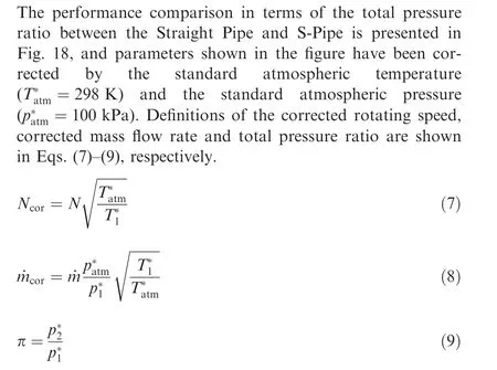
where the subscript‘‘1”and‘‘2”represent the compressor inlet and the compressor outlet, respectively.
The surge boundaries of the two tested compressors are shown in Fig. 18. Compared with that of Straight Pipe, it is clear that at 1.2×10⁵r/min and 1.6×10⁵r/min, the S-Pipe yields smaller surge mass flow rates (Ncor=1.2×10⁵r/min:0.027 kg/s vs 0.031 kg/s & Ncor=1.6×10⁵r/min: 0.040 kg/s vs 0.045 kg/s), which indicates that when the S-shaped inlet pipe is used, better stability performance is achieved. This is a surprising result since it is believed that the S-shaped inlet pipe should exacerbate the compressor stability due to the induced inlet distortion.
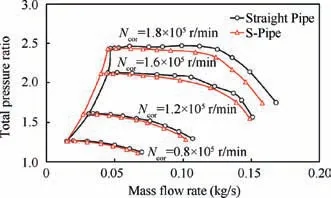
Fig.18 Experimental performance comparison between Straight Pipe and S-Pipe.
According to the analysis in Section 3,the distortion is closely related to the inception of reverse flow, and the voluteinduced distortion plays a dominant role in this process. This means that the influence of the inlet distortion on the stability of a centrifugal compressor is not as large as expected.In addition, analysis of the data shown in Fig. 12 suggested that the centrifugal compressor could tolerate the occurrence of reverse flow to some extent due to the centrifugal effect on pressure rise. Therefore, the authors of this paper deduce that the Sshaped inlet pipe has little influence on the surge boundary of centrifugal compressors because of the dominant influence of the volute-induced distortion and the insensitivity of the centrifugal compressor to reverse flow. For an axial compressor, there is often no volute-induced distortion, and an axial compressor is sensitive to reverse flow because of a lack of a centrifugal effect,so the inlet distortion will significantly influence the surge boundary.
The analysis above indicates that it is reasonable that the Sshaped inlet pipe does not harm the stability of a centrifugal compressor, and the remaining problem is why even a smaller surge mass flow rate could be achieved by an S-Pipe,indicating a great potential to improve compressor stability by designing the bent inlet pipe carefully.According to Fig.18,it is obvious that when the S-shaped inlet pipe is used, both the pressure ratio and the choke mass flow rate (defined as the point of 50% efficiency) decrease. This is because the S-Pipe induces more losses by turning the flow direction and generating a pair of vortices. The extra loss by the S-shaped pipe changes the inlet condition of the compressor, which changes the match between components. To some extent, it is equivalent to scaling the compressor or component to a smaller size, especially for downstream components such as the diffuser, which may be the reason why a smaller surge mass flow rate is obtained when the S-Pipe is used (a smaller compressor often results in smaller surge mass flow rates). However, evidence to support this discussion is lacking, and more related studies are needed to provide a deeper explanation.
5. Conclusions
This paper firstly investigated the flow field and instability evolution process of centrifugal compressors with straight and Sshaped inlet pipes. In addition, it compared and discussed the surge boundaries in detail with experiments.The results reveal that the S-shaped pipe induces a pair of counterrotating vortices and that it has a predominant influence on the flow field structure at a high mass flow rate. In contrast, the flow field structure is mainly decided by reverse flow at a low mass flow rate. Analysis of the instability evolution process reveals that the centrifugal compressor will not go into surge immediately when reverse flow occurs. As the mass flow rate further decreases, the reverse flow region extends circumferentially to the entire annulus and radially to the inner regions. Finally,the compressor loses the ability to increase the pressure, and surge occurs since the reverse flow region is too large.In addition,it is found that reverse flow appears first at flow passages with high pressure differences, and it is not the S-shaped inlet pipe but the volute that plays the dominant role in forming this high pressure difference. Finally, experiments are carried out to compare the surge boundaries of compressors with different inlet pipes, and the results show that the S-shaped inlet pipe will not exacerbate the compressor stability because the volute dominantly contributes to the formation of reverse flow and the compressor will not surge immediately unless the reverse flow region is large enough. Experimental results at some rotating speeds show that the surge mass flow rate of the SPipe could be smaller than that of the Straight Pipe, which indicates the possibility to improve compressor stability by carefully designing the bent inlet pipe. This paper explains how reverse flow occurs and how the surge boundary changes with an S-shaped inlet pipe, and suggests that the influence of bent inlet pipes on the stability of centrifugal compressors is small and enriches the understanding of compressor stability with distorted flow fields.
Acknowledgements
This research was co-supported by the Tsinghua University‘‘Shuimu Tsinghua Scholar” Program, the National Science and Technology Major Project, China (No. 2017-II-0004-0016), the National Natural Science Foundation of China(No. 51876097) and the IHI Corporation, Yokohama, Japan.
 CHINESE JOURNAL OF AERONAUTICS2020年8期
- CHINESE JOURNAL OF AERONAUTICS的其它文章
- Structural dynamic responses of a stripped solar sail subjected to solar radiation pressure
- Dynamic coefficients and stability analysis of a water-lubricated hydrostatic bearing by solving the uncoupled Reynolds equation
- Rotor airfoil aerodynamic design method and wind tunnel test verification
- A heuristic cabin-type component alignment method based on multi-source data fusion
- Effect of curing condition on bonding quality of scarf-repaired composite laminates
- Influence of uniaxial tensile pre-strain on forming limit curve by using biaxial tensile test
