Structural dynamic responses of a stripped solar sail subjected to solar radiation pressure
Junhui ZHANG, N WU, An TONG, Yinghu LIU
a School of Civil Engineering, North China University of Technology, Beijing 100144, China
b School of Aerospace Engineering, Tsinghua University, Beijing 100084, China
KEYWORDS Distributed transfer function method;Frequency response;Solar radiation pressure;Solar sail;Structural dynamic response
Abstract The stripped solar sail whose membrane is divided into separate narrow membrane strips is believed to have the best structural efficiency. In this paper, the stripped solar sail structure is regarded as an assembly made by connecting a number of boom-strip components in sequence.Considering the coupling effects between booms and membrane strips, an exact and semianalytical method to calculate structural dynamic responses of the stripped solar sail subjected to solar radiation pressure is established. The case study of a 100 m stripped solar sail shows that the stripped architecture helps to reduce the static deflections and amplitudes of the steady-state dynamic response. Larger prestress of the membrane strips will decrease stiffness of the sail and increase amplitudes of the steady-state dynamic response. Increasing thickness of the boom will benefit to stability of the sail and reduce the resonant amplitudes. This proposed semi-analytical method provides an efficient analysis tool for structure design and attitude control of the stripped solar sail.
1. Introduction
Gaining propulsive force from solar radiation pressure, the solar sail is a propellantless spacecraft and is considered as the most promising interstellar travel technology.1However,solar radiation pressure is so weak that the solar sail is inevitably designed to be as light-weight and large-area as possible.Several square solar sail architectures as shown in Fig. 1 have been proposed: the four- or five-point suspension sail whose sail membrane is attached to diagonal supporting booms at four or five corner points (Fig. 1(a)), the separate quadrants sail whose whole sail membrane is divided into four separate triangular membranes (Fig. 1(b)), the continuously connected sail whose four separate triangular membranes are continuously attached to diagonal booms(Fig. 1(c)),and the stripped sail whose each triangular membrane is divided into separate narrow strips (Fig. 1(d)). The way the sail membranes are attached to the booms has a large impact on the membrane tension state and boom loads.Among these proposed architectures, the stripped solar sail is believed to have the best structural efficiency, and its manufacturability, ease of folding and packing, scalability, space debris hazard reduction have been demonstrated in the ground-demonstration mission.2,3Then,how to accurately calculate the structural dynamic responses of the stripped solar sail subjected to solar radiation pressure,which are essential in developing appropriate attitude and navigation control algorithms for an orbiting stripped solar sail,is demanded.

Fig. 1 Solar sail suspension patterns.
Except for the stripped solar sail, many structural analyses have been conducted on square solar sails.Murphy et al.4first performed a structural dynamic analysis on a 300 m solar sail by using Finite Element Method(FEM).Holland et al.5,6studied the effect of boom axial loads on global dynamics of a 2 m solar sail and presented the results of experimental modal analysis of two slender cantilever beams considering the effect of gravity and the influence of attached membranes. Taleghani et al.7employed shell finite element models in both MSC/NASTRAN and ABAQUS commercial softwares to predict full scale deformations and vibration modes of a solar sail up to 150 m in size.Sleight and Muheim8performed parametric studies on a five-point connected sail and a continuously connected sail to investigate the effects of sail size, membrane prestress, membrane thickness, and boom stiffness on sail deformations,vibration frequencies,and mode shapes.Stanciulescu et al.9presented the dynamic characteristics of two kinds of sail booms before and beyond buckling. Sakamoto et al.10developed a membrane finite element model which could be used to compute deformed sail shape and obtain total force and moment vectors exerted on the deformed sail.It was found that the sail deformation due to solar radiation pressure could be approximated by the deformation caused by the corresponding uniform gas-pressure. Gaspar et al.11completed a structural characterization experimental test program on a 10 m quadrant component with two supporting booms and a 20 m whole sail with four quadrants and booms. These tests were conducted for the purpose of validating analytical models that would be required by a flight test program to predict the in-space performance. Applying both solar radiation pressure and temperature loads, Sheng et al.12analyzed the deflection and stress distribution of a deployable solar sail using FEM software ANSYS.Liu et al.13presented the structural dynamic results of sail booms undergoing various forces generated by solar radiation pressure, sliding masses and control vanes.Ma et al.14conducted buckling and modal analyses on an 160 m solar sail with and without prestress load. Hassanpour and Damaren15explored the structural dynamics of a solar sail by using a hybrid model including an analytic model to solve the in-plane sail stress and a linear finite element model to account for off-plane defections of the inter-connected sails and booms. Using the inertia relief method, Boni et al.16-18studied the thermal structural dynamic behavior of square solar sails with side length varying from 10 m to 100 m, in which the analysis techniques including effective sail prestress,sufficient mesh refinement and initial geometrical imperfection were introduced to improve the convergence problem.Yang et al.19compared the static and dynamic responses of a 160 m solar sail with an 8 m scalable principle prototype sail.The transient dynamic responses of acceleration,displacement,and vibration amplitudes were evaluated for both the 160 m solar sail and the 8 m prototype sail. Without solar radiation pressure,Zhang et al.20proposed a method to calculate natural frequencies and buckling loads of a stripped solar sail.
Furthermore, structural dynamic characteristics of flexible booms and membranes have also been considered in researches on orbit and attitude control of solar sails.Based on principles of vector mechanics,Cui et al.21deduced the attitude dynamic formulations of two types of flexible solar sails with control vanes and with control booms.Li et al.22formulated a reduced model of a flexible solar sail in mixed coordinates. Using this reduced model, the dynamic responses of a five-point connected square solar sail during maneuvers were investigated.Zhang and Wang23also established a reduced model for a flexible solar sail and designed an attitude controller for the solar sail in a displaced solar orbit. Choi and Damaren24analyzed the behavior of a solar sail under a tip-vane attitude control scheme using a geometrically nonlinear elastic finite element model of the sail. Zhai25formulated the attitude dynamic equations for spinning solar sails which were utilized to estimate angular velocity by using only one sensor. Zhang and Zhou26simulated deployment of a spinning solar sail by using ABAQUS software.The influences of rotational speed and offplane movement of the hub were analyzed with different tip masses, initial velocities, and control parameters. Using the von Karman’s nonlinear strain-displacement relation, Liu and Cui27derived the coupled orbit, attitude, and structural dynamics for a geometrically nonlinear solar sail with sliding masses as attitude control actuators and studied the pitch motions affected by sliding masses.
As stated above, structural dynamic analyses on boomsupporting solar sails have been conducted mostly by using finite element method, in which solving strategies needed to be elaborately designed to overcome numerical difficulties.For stripped solar sail, the author has presented a method to calculate natural frequencies and buckling loads without considering the solar radiation pressure load.20However, for a practical stripped solar sail orbiting in space, solar radiation pressure is the source of propulsive force and the prime mechanical load. Subjected to solar radiation pressure, structural dynamic responses of the stripped solar sail will decrease performance of the attitude and navigation control. Accordingly, this paper aims to establish a semi-analytical method which could be used to accurately predict structural steadystate dynamic responses of a stripped solar sail subjected to solar radiation pressure in space.
2. Mathematical formulations
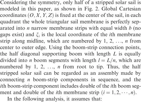


Fig. 2 Half of a stripped solar sail.
(3) The membrane strip is under uniaxial tension stress σsalong the length, instead of the biaxial.
(4) The radius of a boom segment r is much smaller than its length l, i.e. r <<l.
2.1. Transfer functions of the ith boom-strip component subjected to solar radiation pressure
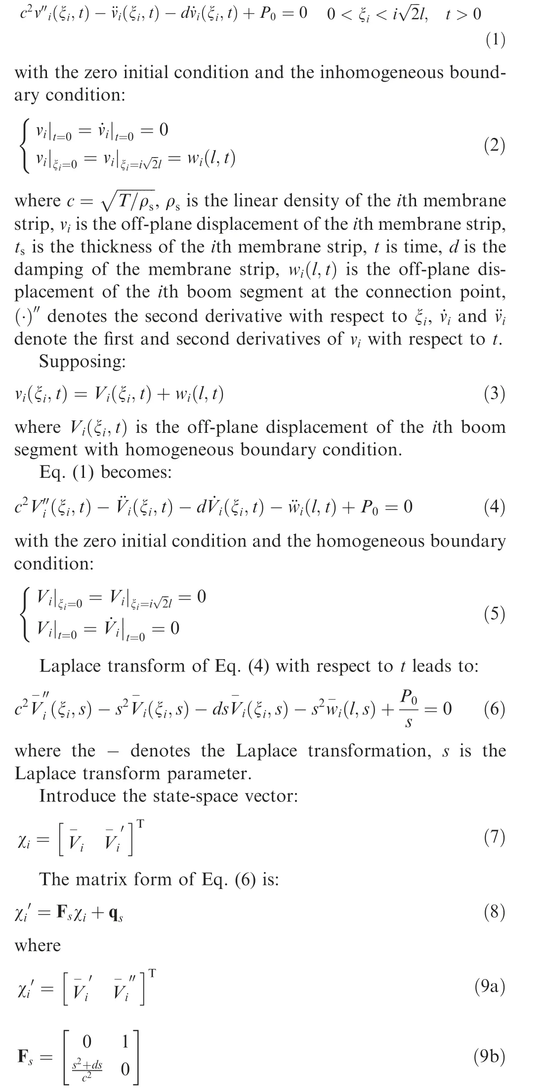
Based on the assumptions(1)and(2),vibration of the ith prestressed membrane strip subjected to solar radiation pressure P0can be simplified as vibration of a string with equivalent tension force T=σsbts:
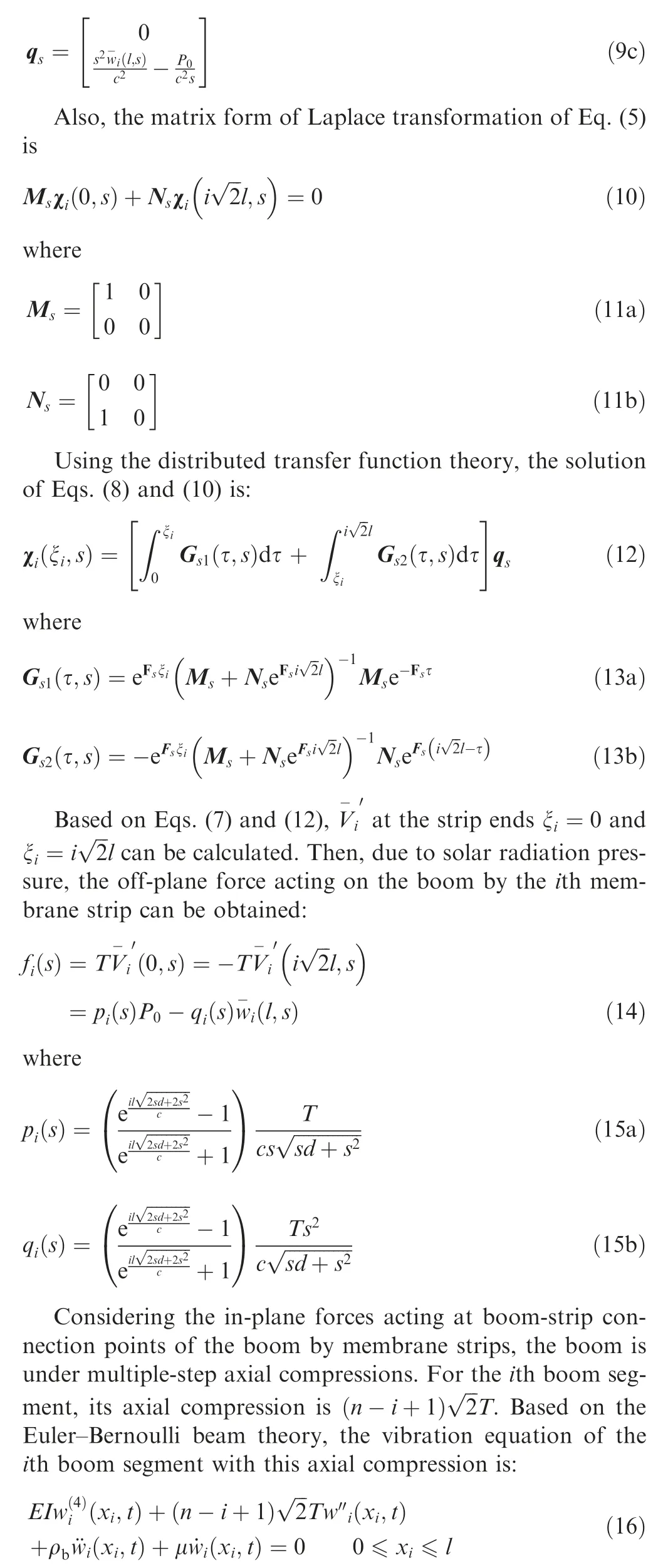
where E is the Young’s modulus of the boom,I is the moment of inertia of the boom cross-section, wiis the off-plane displacement of the ith boom segment, xiis the local axial coordinate of the ith boom segment, ρbis the linear density of the boom,μ is the damping of the boom,(·)(4)denotes the fourthderivative with respect to xi,(·)′′denotes the second derivative with respect to xi, ˙wiand ¨widenote the first and second derivatives of wiwith respect to t.
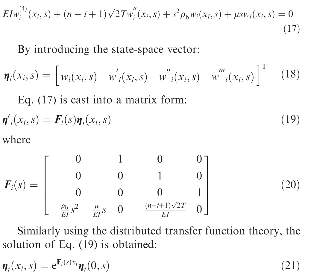
The Laplace transform of Eq. (16) with respect to t yields:
2.2. Assemble boom-strip components into a stripped solar sail
Connecting every boom-strip component in sequence, the n boom-strip components can be assembled into a stripped solar sail. At the ith boom-strip connection point, the connection conditions of deformation and force require:
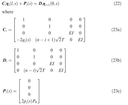
In Eqs. (22) and (23), the first and second rows of the matrixes represent the continuous deformation conditions between the ith boom segment and the (i+1)th boom segment. The third row represents the equilibrium of bending moments, and the fourth row represents the equilibrium of shearing forces with the effect of coupled vibration between boom and strips.
According to Eqs. (21) and (22), it obtains:

Using Eq. (24) repeatedly, gives:
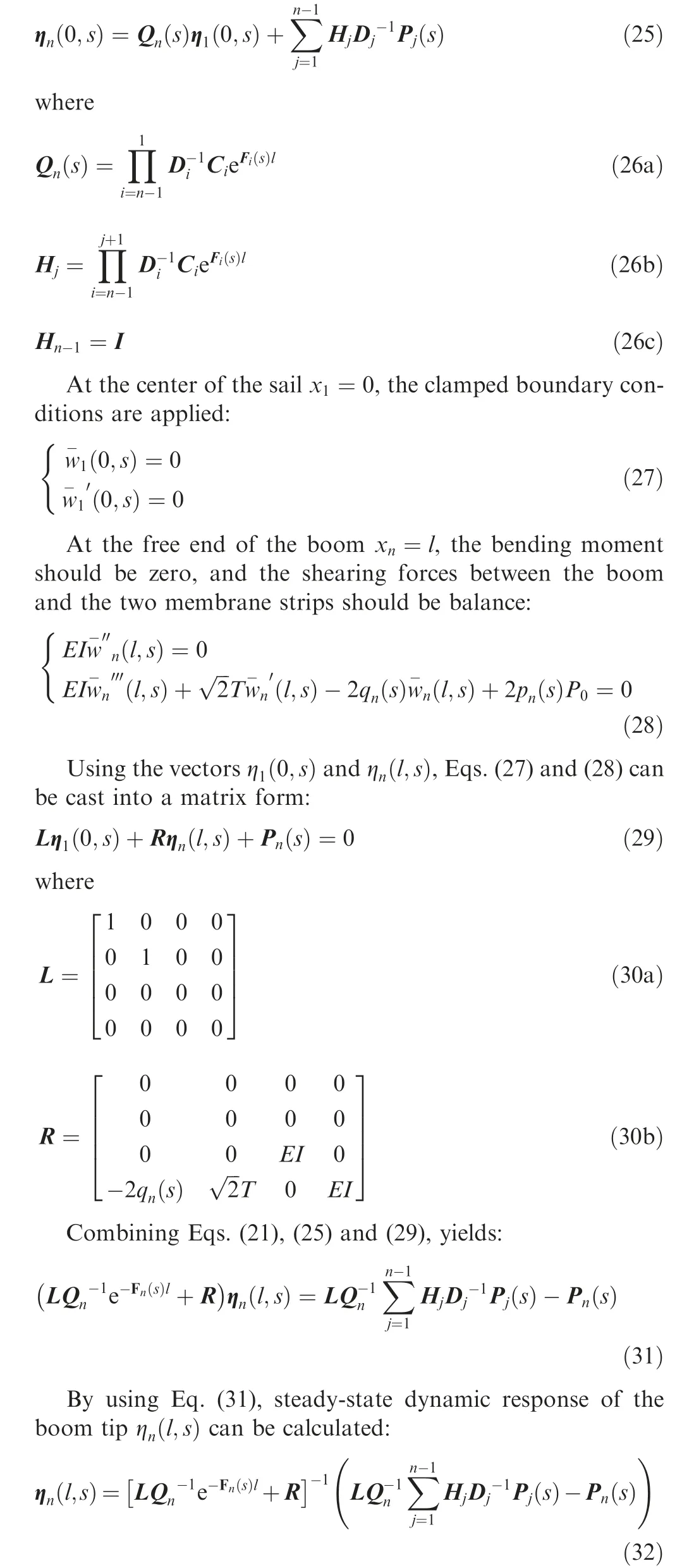
It should be noticed that in this proposed method the matrix dimensions are only 4×4 while using finite element method requires thousands of degrees of freedom and may encounter numerical difficulties.
3. Results and discussion
Several optimal designs of the stripped solar sail have been proposed in Ref.2.In those optimizations,the static deflection of boom tip as one of the interested characteristics has been analyzed,however,dynamic responses of the stripped solar sail subjected to solar radiation pressure were not presented. To illustrate this proposed structural dynamic analysis method,an optimal 100 m stripped solar sail available in Ref. 2 will be used as a case study in this section. The geometric dimensions and material properties of the case stripped solar sail are listed in Table 1.
Subjected to the solar radiation pressure P0=9.126×10⁻⁶Pa at 1 astronomical unit (AU= 1.4959787×10¹¹m),steady-state dynamic responses of the stripped solar sail can be evaluated by using Eq. (32). Under different damping parameters, the response amplitudes of the boom tip varying with frequencies are shown in Fig. 3. It can be found that at ω=0.0, i.e., the static deflection of the boom tip is 3.19 m,that resonance peaks of amplitude correspond with the natural frequencies of the stripped solar sail shown in Ref. 20. At the first resonant frequency, to different damping parameters the response amplitudes of the boom tip all reach the maximum,w=35.84, 12.44, 7.52, 3.98 m when μ=0.001, 0.003,0.005, 0.01.From Fig.3,it can also be found that the damping increase causes a slight decrease in the first resonant frequency and reduces the dynamic amplitudes of all modes.
The number of the membrane strips, stiffness of the boom and prestress of the membrane strips are the important design parameters and have large impact on structural dynamic responses of the stripped solar sail. Thus, parametric studies of n,tband σson frequency responses of the stripped solar sail are presented here.
The effect of boom thickness on frequency response of the boom tip is plotted in Fig.4.It shows that increasing thickness of the boom reduces the static deflections and steady-state dynamic response amplitudes, and it also increases the resonant frequencies. From Fig. 4, it can also be found that for tb=0.1 mm the static deflection is very large and the first frequency response is overdamped, thus, buckling instead of vibration could happen. The effect of the prestress of membrane strips on frequency response of the boom tip is plotted in Fig. 5. It shows that increasing the prestress of membrane strips decrease the resonant frequencies of the sail and increases the static deflections and dynamic response amplitudes. The effect of number of membrane strips on frequency response of the boom tip is plotted in Fig. 6. It shows that more membrane will help to reduce the static deflections and dynamic response amplitudes, which will benefit to attitude and navigation control of the stripped solar sail.
Furthermore, a 20 m solar sail which has been studied in five-point connected pattern by using FEM17will be analyzed by using the proposed semi-analytical method in stripped membrane pattern. The geometric dimensions and material properties of the sail are listed in Table 2.
At 1 AU, for various damping parameters of the membrane, the frequency response amplitudes of the 20 m sail obtained by using Eq. (32) are plotted in Fig. 7. The quasistatic deflection of the boom tip is only 1.60×10⁻⁵m and the first dynamic peak amplitude is 6.81×10⁻⁵m when mem-brane damping d=0.0001, which implies for a small sail the structural dynamic response due to solar radiation pressure may be neglected. Also, increase membrane damping will reduce the dynamic amplitudes of all modes. When d=0.001, all the dynamic responses of membrane strips have been overdamped and only the dynamic responses of the boom can be identified. The effect of boom thickness on frequency response of this 20 m sail is plotted in Fig.8.Similarly,increasing thickness of the boom results in the decrease of structural response amplitudes, but it does not affect the resonant frequencies which correspond with the natural frequencies of membrane strips.

Table 1 Dimensions and material properties of stripped solar sail.

Fig. 3 Frequency response of boom tip of stripped solar sail subjected to solar radiation pressure (d=0).
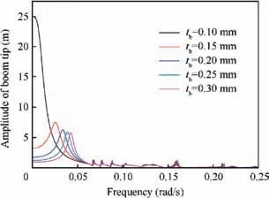
Fig. 4 Effect of thickness of boom on frequency response of boom tip.
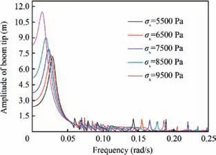
Fig. 5 Effect of prestress of membrane strips on frequency response of boom tip.
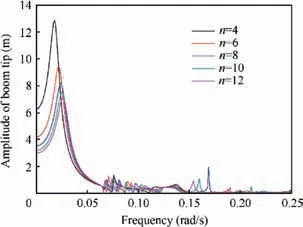
Fig. 6 Effect of number of membrane strips on frequency response of boom tip.
The effect of the prestress of membrane strips on frequency response of the 20 m sail is plotted in Fig. 9. Surprisingly, as increasing the prestress of membrane strips, the first resonant frequencies increase, which is different from the Fig. 5;quasi-static and dynamic response amplitudes increase, which is same to the Fig. 5. The sail size may cause this difference,because for a small sail the dynamic response of membrane strips will dominate the low mode frequencies which are positively affected by the prestress. The effect of the number of membrane strips on frequency response of the 20 m sail is plotted in Fig. 10, like Fig. 6, which shows more membrane can reduce the quasi-static deflections and dynamic response amplitudes and is benefit to stability of the stripped solar sail.The effect of sail size on frequency response of the stripped solar sail is plotted in Fig. 11, it shows as the sail size increasing the quasi-static deflections and dynamic response amplitudes dramatically increase.
4. Conclusions
Considering coupled vibration between membrane strips and booms, a dynamic model of stripped solar sail is established.Based on the distributed transfer function theory,an exact and semi-analytical method to predict steady-state dynamic responses of the stripped solar sail subjected to solar radiation pressure is proposed in this paper.

Table 2 Dimensions and material properties of the 20 m stripped solar sail.
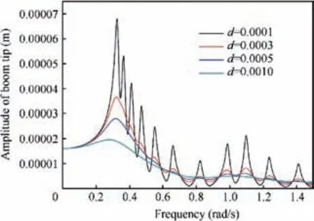
Fig. 7 Effect of damping of membrane strips on frequency response of 20 m sail.
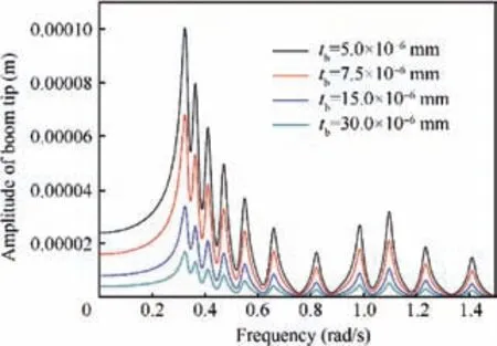
Fig. 8 Effect of thickness of boom on frequency response of 20 m sail.
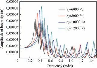
Fig. 9 Effect of prestress of membrane strips on frequency response of 20 m sail.
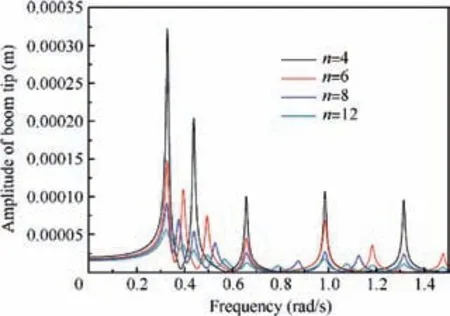
Fig. 10 Effect of number of membrane strips on frequency response of 20 m sail.
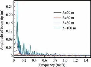
Fig.11 Effect of sail size on frequency response of stripped solar sail.
(1) Increasing thickness of the boom will reduce static deflections and steady-state dynamic response amplitudes of the stripped solar sail, and it will also slightly increase the resonant frequencies. Thicker boom is benefit to stability of the stripped solar sail.
(2) Increasing prestress of the membrane strips will increase the static deflections and dynamic response amplitudes,which is harmful to the sail performance.Too large prestress may cause the boom buckling.
(3) More membrane strips will help to reduce the static deflections and amplitudes of the steady-state dynamic response, which benefits to attitude and navigation control of the stripped solar sail.
(4) Increasing damping can efficiently reduce the dynamic response amplitudes of all modes, while increasing the sail size will dramatically increase the dynamic response amplitudes.
Acknowledgement
This study was supported by the National Natural Science Foundation of China (No. 11572001).
 CHINESE JOURNAL OF AERONAUTICS2020年8期
- CHINESE JOURNAL OF AERONAUTICS的其它文章
- Dynamic coefficients and stability analysis of a water-lubricated hydrostatic bearing by solving the uncoupled Reynolds equation
- Rotor airfoil aerodynamic design method and wind tunnel test verification
- A heuristic cabin-type component alignment method based on multi-source data fusion
- Effect of curing condition on bonding quality of scarf-repaired composite laminates
- Influence of uniaxial tensile pre-strain on forming limit curve by using biaxial tensile test
- Influence of non-equilibrium reactions on the optimization of aerothrust aeroassisted maneuver with orbital change
