Influence of non-equilibrium reactions on the optimization of aerothrust aeroassisted maneuver with orbital change
Nikoly A. ELISOV, Sergey A. ISHKOV, Igor A. LOMAKA,Vlentin G. SHAKHOV
a Department of Space Engineering, Samara National Research University, Samara 443086, Russia
b Inter-University Department of Space Research, Samara National Research University, Samara 443086, Russia
c Department of Aircraft Construction and Design, Samara National Research University, Samara 443086, Russia
KEYWORDS Atmospheric entry;Boundary value problem;Computational fluid dynamics;Differential evolution;Flight mechanics;Non-equilibrium flow;Spaceplane
Abstract The spaceplane is perspective vehicle due to wide maneuverability in comparison with a space capsule.Its maneuverability is expressed by the larger flight range and also by a possibility to rotate orbital inclination in the atmosphere by the aerodynamic and thrust forces. Orbital plane atmospheric rotation maneuvers can significantly reduce fuel costs compared to rocket-dynamic non-coplanar maneuver. However, this maneuver occurs at Mach numbers about 25, and such velocities lead to non-equilibrium chemical reactions in the shock wave. Such reactions change a physicochemical air property, and it affects aerodynamic coefficients. This paper investigates the influence of non-equilibrium reactions on the aerothrust aeroassisted maneuver with orbital change.The approach is to solve an optimization problem using the differential evolution algorithm with a temperature limitation. The spaceplane aerodynamic coefficients are determined by the numerical solution of the Reynolds-averaged Navier-Stokes equations.The aerodynamic calculations are conducted for the cases of perfect and non-equilibrium gases. A comparison of optimal trajectories,control laws,and fuel costs is made between models of perfect and non-equilibrium gases.The effect of a chemically reacting gas on the finite parameters is also evaluated using control laws obtained for a perfect gas.
1. Introduction
London was among the first who proposed to rotate orbital inclination by aerodynamic forces (two-channel control) in the atmosphere in 1962.1The maneuver scheme is presented in Fig. 1 and can be divided into three stages: (A) A braking impulse is applied to descend from the initial orbit and then to enter into the atmosphere (ΔV1); (B) A spaceplane rotates the orbital plane and flies out from the atmosphere using the attack angle and bank angle(which is a roll around the velocity vector)control channels;(C)The ascent to the final orbit is carried out according to the impulse theory (ΔV2and ΔV3).
Later, Shkadov established that fuel costs are directly proportional to the orbital inclination rotation and inversely proportional to the maximum lift-to-drag ratio.2Two-channel control allows rotating the orbital plane by 5° without significant fuel costs in comparison with the rocket-dynamic maneuver.1,2Joosten and Pierson also came to similar conclusions.3He got control programs taking into account the temperature limit and concluded that the bank angle plays more significant role than the attack angle.Further development of this maneuver was carried out by Lasarev.4The development included adding to the attack angle and bank angle control channels the thrust control channel (three-channel control). This improvement made it possible to rotate the orbital plane at large angles while preserving the maneuver efficiency compared to the rocket-dynamic maneuver.
The problem of the aerothrust aeroassisted maneuver with orbital change was solved by the maximum principle,5by the method of sequential linearization6and by the hp-adaptive Gaussian quadrature collocation.7,8Ref. 5 is devoted to the definition of strict control laws while rotating the orbital plane by 15° without temperature limitation. It follows from this work that one of the disadvantages of the maximum principle is the difficulty in determining the initial approximation of solution in the presence of constraints on the phase parameters. Ref. 6 presents the results of the orbital plane rotation optimization, taking into account temperature limitations. As indicated in Ref. 6, the control linearization is carried out at each step, which leads to the accumulation of optimization errors due to the approximate numerical calculation of the fitness function. Rao7,8presented optimal control programs and trajectories for a small spacecraft using the hp-adaptive pseudospectral method.
This paper uses the differential evolution algorithm as an optimization method, which was first proposed by Storn and Price in 1995.9The simplicity of implementation and efficiency of the algorithm led to its popularity among researchers from various fields of science. For example, Kim et al.10assessed damage and vibration in plane and space trusses and found out that differential evolution is much more efficient than other genetic algorithms. Ref. 11 considers the rescheduling order problem in the steel industry using a modified differential evolution algorithm.According to the authors,obtained optimization results are introduced into the iron and steel industry. In another logistic problem,12an improved differential evolution algorithm was used to form optimal control of an unmanned aerial vehicle.Also,this algorithm successfully solved the robot navigation problem,13which allowed achieving the goal point in the presence of various obstacles, as well as choosing the optimal route.In addition to these problems,differential evolution is also successfully used in problems of aviation and astronautics. Belokonov et al.14determined the spacecraft attitude and the moments of inertia by the data from the solar panels current using the differential evolution algorithm.Ref.15 synthesized control of the spacecraft attitude,taking into account pointing and boundary limitations.As the authors note,differential evolution reduced the attitude maneuver time subject to limitations. Wang et al.16searched for the optimal trajectories of a robotic manipulator to capture space debris and confirmed the effectiveness of the method. Ref. 17 presented a comparative analysis between the maximum principle and differential evolution in the problem of aerothrust aeroassisted maneuver with orbital change.The difference in the spaceplane finite mass between both optimization methods was 0.3%.It can be noted that one of the disadvantages of differential evolution is multiple references to the optimizing function,which increases calculation time. Another disadvantage is necessity to specify an initial form of control function for solving the boundary value problems, which can narrow the search for the optimal solution.
Since this maneuver occurs at Mach number about 25,nonequilibrium reactions arising in the shock wave are no less attractive.18These reactions lead to a change in the air physicochemical property.19-21Such changes affect the aircraft aerodynamic characteristics.22Among the first who studied the hypersonic flow problem was Dorrance.23He cited formulas for calculating the drag coefficient for cone-shaped bodies, a flat plate and a thin plate with a small bluntness. At the same time,Dorrance noted that the calculation of blunted bodies in the hypersonic flight regime is a rather difficult problem,which is related to determining the shock stand-off distance.
Due to the active development of Computational Fluid Dynamics(CFD),it became possible to simulate such complex processes as hypersonic flow with non-equilibrium reactions with good accuracy.24Refs. 25,26 also show that CFD has quite a good agreement with the experimental data on the example of hypersonic Earth flow and Martian flow, respectively. Despite good accuracy, some researchers suggest improvements to the CFD methods that are commonly used in the simulation. Typically, improvements are made to the turbulence model27,28to improve the prediction accuracy of the hypersonic flow.Other researchers have proposed their calculation methods for solving specific problems.29On the other hand, comparisons are made between the existing methods,e.g., flux stream scheme30and also strategies are proposed for solving specific problems.31It is worth noting that questions related to non-equilibrium reactions remain still poorly understood due to the complexity of carrying out the corresponding experiments.It is expressed primarily in the presence of different chemical kinetic models.32-35The highest accuracy in a particular physical aspect depends on the chosen chemical kinetic model.36-38
This article raises questions related to the influence of nonequilibrium flow on the dynamics of the orbital plane atmospheric rotation. Section 2 describes a mathematical model of the spaceplane motion as a point mass and describes the equations of chemically reacting air. Section 3 presents a model of a hypothetical spaceplane and the creation of a grid.Also,it provides grid parameters for studying its convergence.Section 4 addresses the optimization problem for the orbital plane atmospheric rotation and presents the settings of the solver for aerodynamic simulation.Section 5 shows the results of an aerodynamic study of the spaceplane for models of perfect and non-equilibrium gases. The results of trajectory optimization for perfect and non-equilibrium gases are presented. The influence of non-equilibrium reactions on the finite flight conditions by substitution of aerodynamic coefficients in nonequilibrium gas into the control laws obtained for a perfect gas is assessed.
Spaceplanes are still interesting objects of study because,when they are designed, it is necessary to solve multiple problems associated with hypersonic aerodynamics, heat transfer,strength, control, etc.
2. Mathematics model
2.1. Flight dynamics
It is not necessary for the descent stage to solve the optimization problem;it only obtains the initial conditions for entering the atmosphere. At the remaining stages, the spaceplane flight occurs under the influence of gravitational, aerodynamic, and thrust forces.It is more convenient to carry out the control synthesis in the mobile trajectory coordinate system. X-axis coincides with the direction of the spaceplane velocity, and Y-axis is a vertical plane passing through the X-axis and is directed upward from the Earth surface.39The chosen coordinate system is non-inertial, and the maneuver also occurs under the influence of Coriolis and transport accelerations. The system of differential equations in the coordinate trajectory system describing mass center motion has the following form:
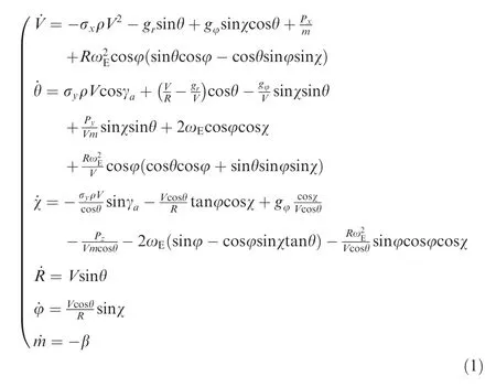
where V is spaceplane velocity, θ is trajectory angle, χ is path angle, R is radius-vector of mass center, φ is geocentric latitude, m is spaceplane mass, σx, σyare ballistic coefficients, ρ is air density, gr, gφare radial and meridional components of the gravitational acceleration respectively, Px, Py, Pzare projections of thrust on the corresponding axis, ωEis angular velocity of Earth rotation, γais bank angle, and β is fuel consumption.
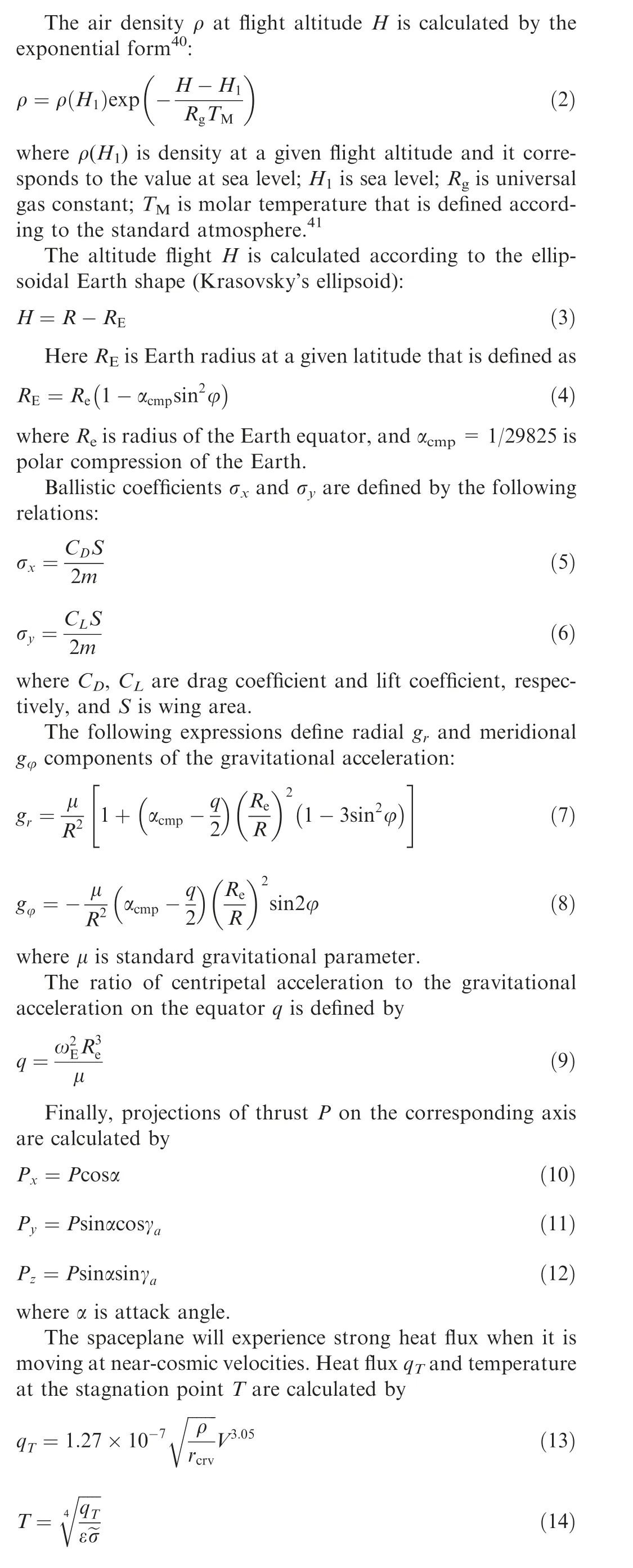
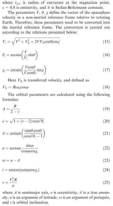
2.2. Flow equations
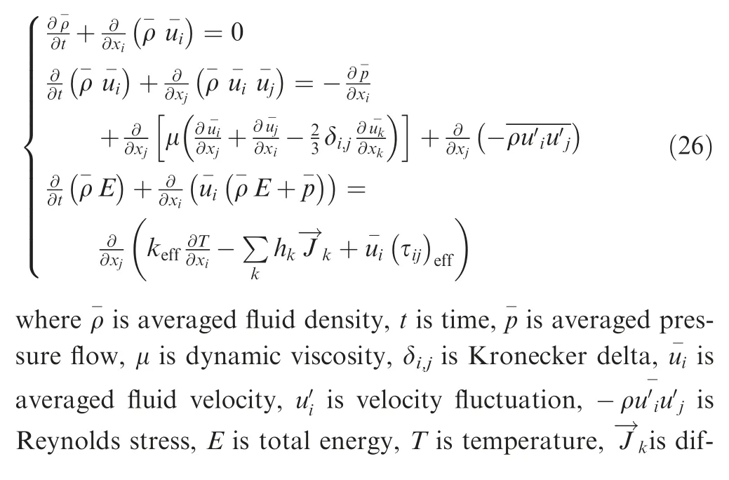
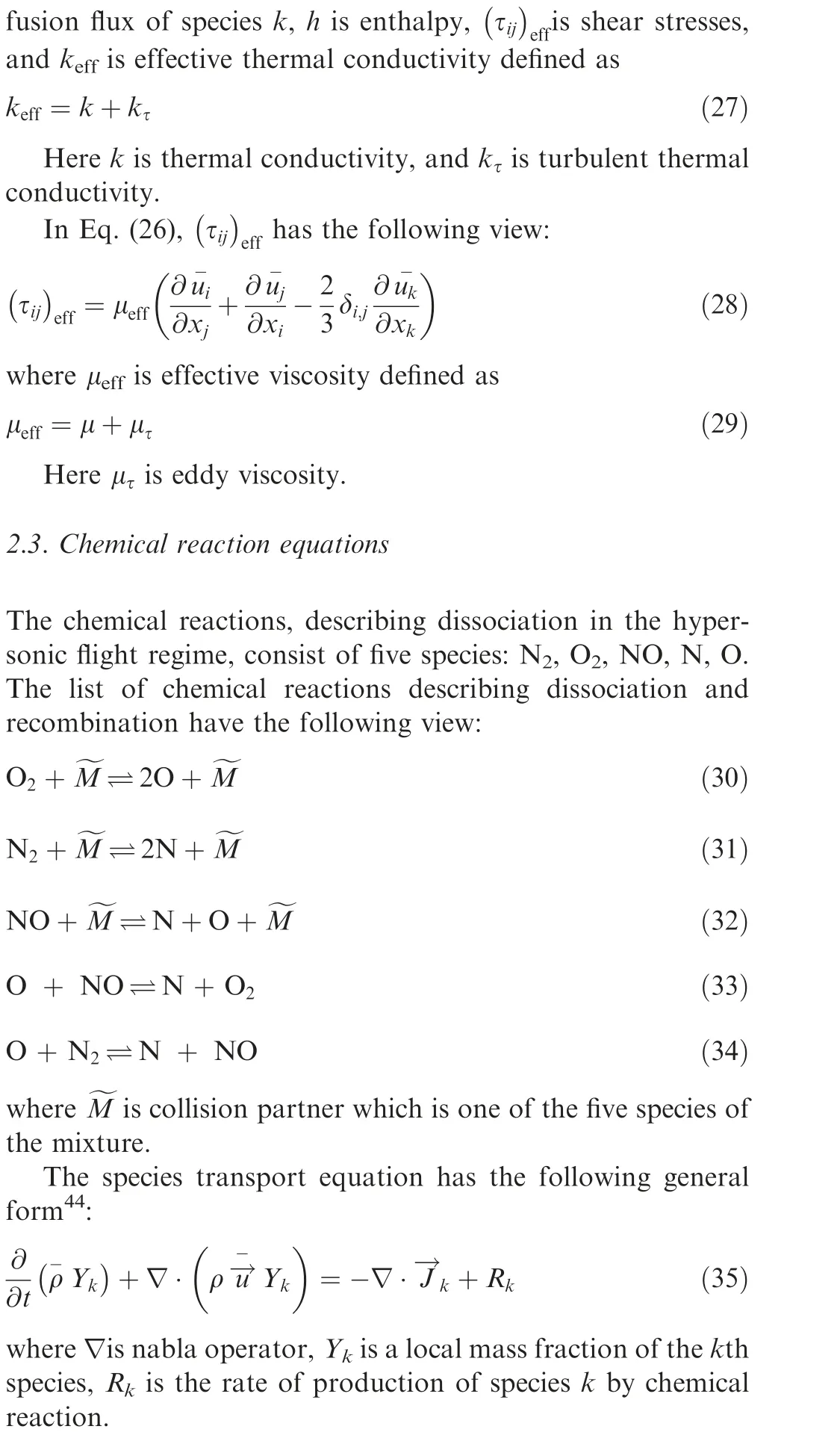
Computational fluid dynamics methods are used to determine the drag coefficient CDand lift coefficient CLby solving Reynolds-averaged Navier-Stokes equations42,43:
3. Geometrics model
In this paper, we are examining a hypothetical spaceplane shown in Fig. 2. The spaceplane has the following reference parameters: the surface is 18.44 m2, the length is 14.66 m,and the mean aerodynamic chord is 2.3 m.
The computational domain has a shape of parabola because this form allows reducing number of mesh elements that is very important for simulation of hypersonic flow.
For our task, a block-structured mesh was generated using ICEM CFD due to flexibly configuring parameters such as quality and near-wall layer thickness. To improve the quality of the mesh, O-grid was created separately for the fuselage,wing, and empennage. The surface grid is shown in Fig. 3.
The minimum orthogonality is 0.2, and the maximum aspect ratio is 163. The value of the near-wall layer thickness is 1 mm. Parameters of mesh for grid convergence study are represented in Table 1.
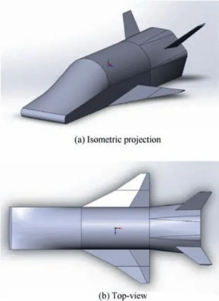
Fig. 2 Geometrics model.
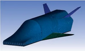
Fig. 3 Surface grid.

Table 1 Parameters of grid.
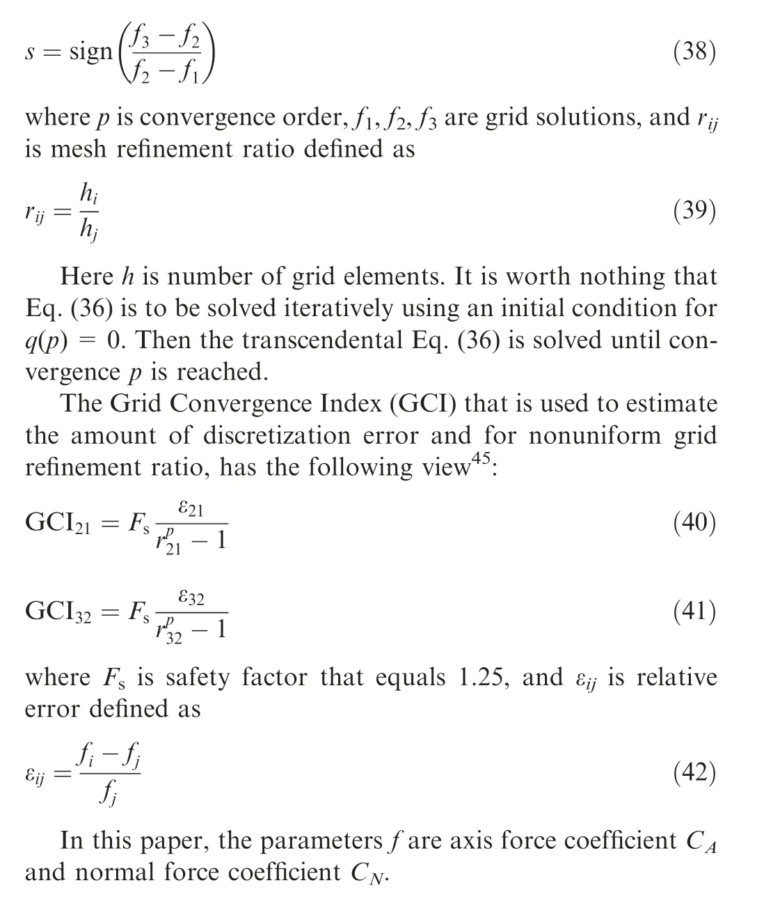
For three-dimensional problems, a constant mesh refinement can be a computational burden. Therefore, it is most practical to use nonuniform grid refinement ratios with values that are greater than 1.3.The following extrapolation that can be used to assess the grid convergence with nonuniform grid refinement ratios, has the following view45:

4. Numerical approaches
Optimization task can be formulated as follows:it is necessary to synthesize a three-channel control using attack angle α,bank angle γaand thrust P, which maximizes a finite spaceplane mass during a change of orbital inclination i by 5°, 10°and 15° with temperature limitation at the stagnation point.Boundary conditions are presented in Table 2.
Engine parameters and limitations on control and temperature are presented in Table 3.
As mentioned above, the differential evolution algorithm requires the initial form of control functions. As Refs. 2-6 showed,the dependences of attack angle and bank angle from time can be quite complicated. Thus, attack angle α(t) and bank angle γa(t)can be decomposed into Fourier series,which can describe a complex dependence and be easily scaled in time:
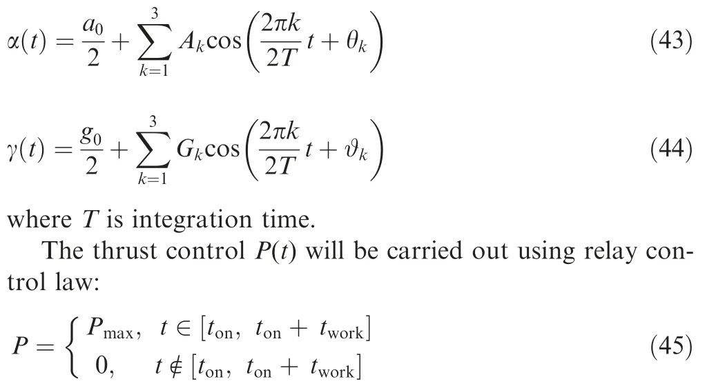
where tonis engine start time; tworkis engine operation time.
The system of differential equations (Eq. (1)) and control laws (Eqs. (43)-(45)) define the kind of optimal trajectory.

Table 2 Boundary conditions.
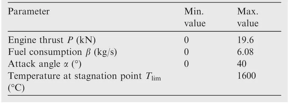
Table 3 Engine parameters and limitations.
The desired optimal trajectory is determined from the boundary conditions of the boundary value problem:
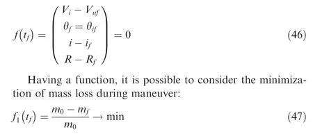
Thus,the differential evolution algorithm will minimize the following function:

The penalty function method can be used to take into account the limitation on the allowable temperature at the stagnation point Tlim. If the permissible temperature at the stagnation point T(Eq.(14))is exceeded,the following penalty is imposed on the functional F(tk):

where Q is positive integer.
Stopping criterion is the standard deviation of engine start time ton<0.5.
The aerodynamic calculations are performed using ANSYS Fluent due to its wide possibilities for fluid dynamics tasks and high fault tolerance of the solver. It is necessary to define Knudsen number Kn to determine the flight altitude at which the continuum theory is still applicable:

where λ is mean free path; L is spaceplane length.
Knudsen number calculation is presented in Table 4.

Table 4 Knudsen numbers.
As Table 4 shows, Knudsen number is lesser than 0.01.Therefore, aerodynamic calculations can be performed without slip. Flight parameters for simulating are represented in Table 5.
It is necessary to determine Reynolds number Re to select the flow regime in the simulation:

where V∞is flow velocity;Lmacis mean aerodynamic chord; ν is kinematic viscosity.
Reynolds number for flight altitude of 70 km is equal to 98404.2, which corresponds to the laminar flow regime. Thus,the laminar finite-rate model is chosen for the calculation of the reaction rate Rk. Reaction rate is calculated as the sum of the Arrhenius reaction sources over the n reactions41:

where Mkis the molecular mass of species k; ^Rk,ris Arrhenius molar rate of creation/destruction of species k in reaction r.
The net rate of creation of the kth species in reaction r has the following view:
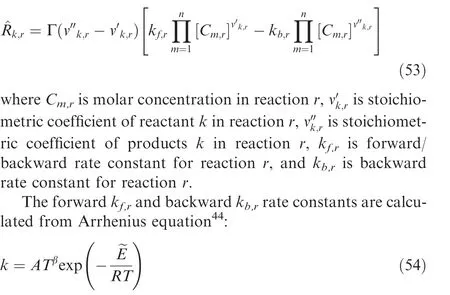
where A is pre-exponential factor, T is temperature, β is temperature exponent,is activation energy, and R is universal gas constant.
The density-based solver is used to simulate compressible flow. The Advection Upstream Splitting Method was chosen for accuracy describing compressible flows with convective flux stream scheme which provides sufficient accuracy of contact and shock discontinuities. The second-order of accuracy and double-precision are adopted for the solution due to the complex formulation of the problem,and also control of the Courant number is used.

Table 5 Flight parameters.
Chemical reactions were designed using ANSYS ChemKin and then exported to Fluent. The temperature in the shock wave reaches huge values at large Mach numbers, and then the use of default ANSYS ChemKin database46for specific heat is unacceptable. NASA9 polynomials were used to describe the specific heat for the species involved in the nonequilibrium reactions.47
The Sutherland law defines the dynamic viscosity for molecular species O2,N2,NO.However,the dynamic viscosity for atomic species (O, N) cannot be specified through the Sutherland law. Thus, the following polynomials for dynamic viscosity of atomic oxygen O and atomic nitrogen N can be used19:

The thermal conductivity λ for individual species is determined from the kinetic theory.Then the parameters of specific heat cp, dynamic viscosity μ, thermal conductivity λ, and density ρ for the mixture are calculated following the ideal gas mixing law.33Mass fractions for nitrogen N2and oxygen O2were taken 79% and 21% respectively.
The drag coefficient CDand lift coefficient CLfor large Mach numbers slightly depend on the Mach number. Thus,these coefficients can be expressed using bicubic interpolation as functions of flight altitude H and attack angle α48:

Knowing the drag coefficient CDand lift coefficient CLat given altitude flight H and attack angle α, coefficients a and b can be determined by solving a system of linear algebraic equations. Since flight trajectory has a non-atmospheric part,the values of drag and lift coefficients at an altitude above 100 km will be taken as 100 km because the air density is extremely small at these altitudes and aerodynamic forces will not affect the final result.
5. Discussion
5.1. Validation
Before proceeding to the aerodynamic calculations of the spaceplane, it is necessary to validate the settings of ANSYS Fluent solver. Validation is carried out for the cone with 30°half-angle at a Mach number of 22 at an altitude of 65 km.18According to Ref. 18, the shock layer thickness decreases,the density behind the shock wave increases, and the pressure behind the shock wave decreases by 8%in the non-equilibrium gas compared to the perfect gas.18
To estimate the methodological error,the mesh for the cone was also generated with the near-wall layer thickness of 1 mm,as for the spaceplane. The simulation results show that the shock layer thickness decreased and the density behind the shock wave increased (Fig. 4). The pressure behind the shock wave also decreased by 5.2% (Fig. 5(a) and (b)).
Thus, the relative pressure difference between obtained results and experimental results18is 2.8% that indicates good agreement. Therefore, ANSYS Fluent can be used to determine the spaceplane aerodynamic characteristics.
5.2. Aerodynamic results
Results were gained using Samara National Research University supercomputer Sergey Korolev. The sign of the computation convergence is a change of the coefficients CAand CNby 0.00001 and 0.0001 per 30 iterations respectively.
As shown in Figs. 6 and 7, the calculations of the coefficients CAand CNon all grids come to an asymptotic form.The convergence order p and grid convergence index GCI results are presented in Table 6.
As can be seen from Table 6,the solutions between the difference grids have good convergence. Thus, further calculations were carried out for the grid with 4.9 million elements,because this grid provides sufficient accuracy of the computation. Such a grid also decreases the calculation time.
The shock layer thickness (Fig. 8) decreased by about 46.7% for a non-equilibrium gas, which led to an increase in density behind the shock wave in comparison with a perfect gas. Abscissa axis value equal to 0 corresponds to the spaceplane front point. The pressure behind the shock wave increased by 5.64% (Fig. 9), which indirectly confirms its behavior in a chemically reactive gas for a blunt body.49
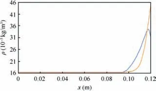
Fig. 4 Comparison of shock layer thickness between a perfect gas (solid line) and a non-equilibrium gas (dashed line).
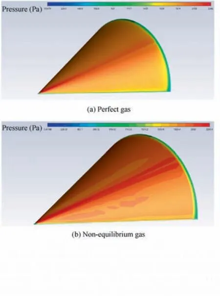
Fig. 5 Pressure contour of cone.
The species mass fraction contours are presented in Fig. 6 for a flight altitude of 80 km and zero attack angle.The molecular oxygen O2fully dissociated at a Mach number of 25(Fig.10(a)and(c)).Despite the large Mach number,molecular nitrogen N2dissociated by 36.4%due to the high value of activation energy (Fig. 10(b) and (d)). The maximum molecular concentration of nitrogen monoxide NO is placed between a nose and wing and also behind the spaceplane (Fig. 10(e)).Its maximum value is 4.1%.
The calculation results of drag coefficients CD, lift coefficients CL,and lift-to-drag ratios L/D are presented in Figs.11-13,respectively.The drag coefficient for a non-equilibrium gas is a bit lesser in comparison with a perfect gas at small attack angles (Fig.11). However, its values become larger than those for a perfect gas at a large attack angle range. Wherein, the influence of non-equilibrium reactions on the drag coefficient increases with increasing flight altitude at a large attack angle range.
On the other hand,the lift coefficient for a non-equilibrium gas is a bit larger in comparison with a perfect gas(Fig.12)for flight altitudes of 70 km and 80 km. However, its value becomes lesser for a non-equilibrium gas for flight altitudes of 90 km and 100 km. Wherein, the influence of nonequilibrium reactions on the lift coefficient also increases with increasing flight altitude.
The maximum lift-to-drag ratio for a perfect gas and nonequilibrium gas is achieved for different attack angles(Fig.13)due to a difference of drag and lift coefficients between a perfect gas and a non-equilibrium gas.
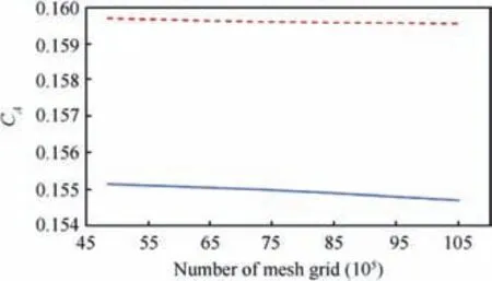
Fig. 6 Axial force coefficient versus number of mesh grid in a perfect gas (solid line) and a non-equilibrium gas (dashed line).
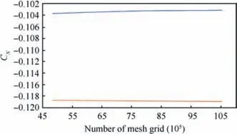
Fig.7 Normal force coefficient versus number of mesh grid in a perfect gas (solid line) and a on-equilibrium gas (dashed line).
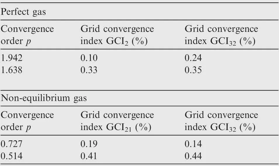
Table 6 Convergence order and grid convergence index.
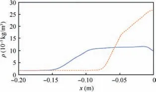
Fig. 8 Comparison of shock layer thickness between a perfect gas (solid line) and a non-equilibrium gas (dashed line) at a flight altitude of 80 km and attack angle of 0°.
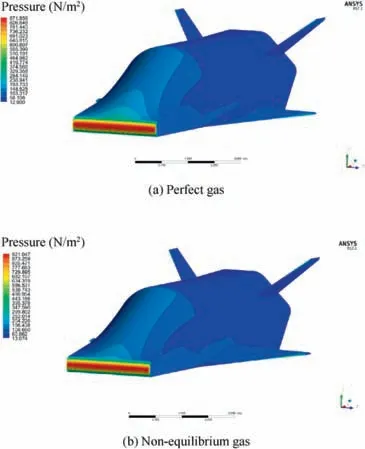
Fig. 9 Pressure contour of spaceplane at a flight altitude of 80 km and attack angle of 0°.
The numerical interval is divided into two intervals with ranges of attack angle from 4° to 16° and from 16° to 40° to improve the interpolation accuracy of drag (Fig. 14) and lift(Fig. 15) coefficients. The zero angle of attack is not used in interpolation due to its low practical significance. As can be seen from Figs. 14 and 15, interpolation accuracy is quite good, and the interpolation error does not exceed 10-5.
5.3. Flight dynamics results
The general view of the optimality criterion depending on the iterations number is shown in Fig. 16.
Optimal trajectories were close for perfect gas and nonequilibrium gas during rotating the orbit plane by 5°(Fig. 17). Fuel costs were also close and amounted to 16.4%and 16.5% from the initial mass for perfect and nonequilibrium gases respectively.Despite the trajectories proximity, the control structures for both gas models are different(Figs. 17 and 18). Attack angle α has deviation less than 1°for a non-equilibrium gas in comparison with a perfect gas(Fig. 18). Wherein, the difference in the bank angles is more distinct between two gas models. Bank angle is constant until the maneuver time is 400 s for a non-equilibrium gas. In the case of a perfect gas,the spaceplane enters with a smaller bank angle and constantly increases it. It also differs from the time of the first and second start and engine operation for two gas models (Fig. 17).
Application of the control laws obtained for a perfect gas in the model of a non-equilibrium gas leads to orbital altitude error equal to 30 km (Fig. 19). At the same time, the orbital inclination hardly changes. It is necessary to increase engine operation time during the second switch-on by 5 s, which is equivalent to additional fuel costs of 30 kg to compensate the altitude loss. The error of the orbital inclination does not increase much due to the additional engine operation time.

Fig. 10 Mass fraction contour at a flight altitude of 80 km and attack angle of 0°.
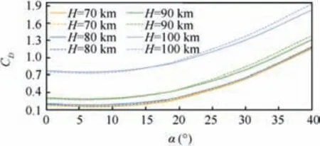
Fig.11 Comparison of drag coefficients CD between perfect gas(solid lines) and non-equilibrium gas (dashed lines).
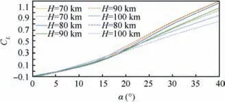
Fig. 12 Comparison of lift coefficients CL between perfect gas(solid lines) and non-equilibrium gas (dashed lines).
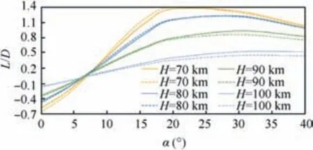
Fig. 13 Comparison of lift-to-drag ratios L/D between perfect gas (solid lines) and non-equilibrium gas (dashed lines).
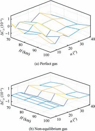
Fig. 14 Interpolation errors of drag coefficient.
Altitude and orbital inclinations have more distinct difference during rotating the orbit plane by 10° (Fig. 20). At the same time, fuel costs amounted to 27.6% and 28.1% from the initial mass for perfect and non-equilibrium gases respectively. The time of the engine second start also occurs later in non-equilibrium gas, as well as when the orbit is rotated by 5°.As can be seen from Fig. 21, a spaceplane is maneuvering with a smaller bank angle in a non-equilibrium gas in comparison with a perfect gas.Wherein the difference between the attack angles in two gas models becomes more distinct in comparison with the rotation of orbital inclination by 5°.
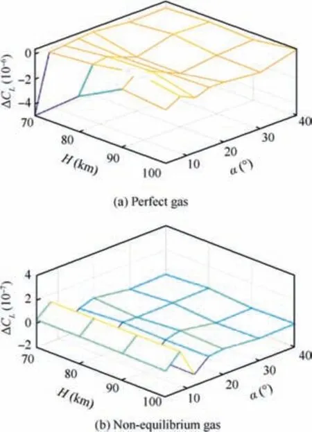
Fig. 15 Interpolation errors of lift coefficient.

Fig.17 Flight altitudes H,orbital inclinations i,temperatures at stagnation point T and thrust P versus time during rotating the orbital plane by 5°for cases of a perfect gas(solid lines)and a nonequilibrium gas (dashed lines).
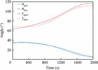
Fig. 18 Comparison of control laws of attack angle α and bank angle γa during rotating the orbital plane by 5° for cases of a perfect gas (solid lines) and a non-equilibrium gas (dashed lines).
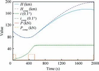
Fig.19 Application of control laws obtained for a perfect gas in a model of non-equilibrium gas (solid lines) and compensation of altitude loss (dashed lines).
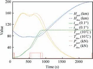
Fig.20 Flight altitudes H,orbital inclinations i,temperatures at stagnation point T and thrust P versus time during rotating the orbital plane by 10° for cases of a perfect gas (solid lines) and a non-equilibrium gas (dashed lines).
The application of the control laws obtained for a perfect gas in the model of a non-equilibrium gas leads to orbital altitude loss equal to 65 km (Fig. 22). It is necessary to increase the engine operation time during the second switch-on by 10 s for compensating the orbital altitude loss, which is equivalent to additional fuel costs of 60.2 kg. However, this increment leads to the increase of error for orbital inclination by 0.3°.
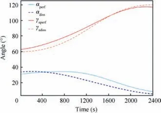
Fig. 21 Comparison of control laws of attack angle α and bank angle γa during rotating the orbital plane by 10° for cases of a perfect gas (solid lines) and a non-equilibrium gas (dashed lines).
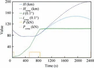
Fig.22 Application of control laws obtained for a perfect gas in a model of non-equilibrium gas (solid lines) and compensation of altitude loss (dashed lines).
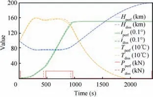
Fig.23 Flight altitudes H,orbital inclinations i,temperatures at stagnation point T and thrust P versus time during rotating the orbital plane by 15° for cases of a perfect gas (solid lines) and a non-equilibrium gas (dashed lines).
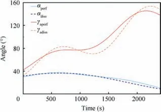
Fig. 24 Comparison of control laws of attack angle α and bank angle γa during rotating the orbital plane by 15° for cases of a perfect gas (solid lines) and a non-equilibrium gas (dashed lines).
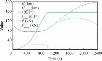
Fig.25 Application of control laws obtained for a perfect gas in a model of non-equilibrium gas (solid lines) and compensation of altitude loss (dashed lines).
The optimal trajectory was close for perfect and nonequilibrium gases during rotating the orbital inclination by 15° (Fig. 23). Fuel costs were 38.2% and 38.3% for perfect and non-equilibrium gases respectively. The second engine start occurs earlier in a non-equilibrium gas in contrast to the task of rotating the orbital inclination by 5° and 10°. Despite the proximity of the optimal trajectories and the finite masses values,the bank angle control channel is significantly different for two gas models (Fig. 24). The dependence of the attack angle for both gas models is similar to the dependence during the orbit plane rotation by 10°.
Application of the control laws obtained for a perfect gas in the model of a non-equilibrium gas leads to a significant error of orbital altitude (Fig. 25). This error is due to insufficient engine operation time at the second start. Therefore, it is necessary to increase engine operation time during the second switch-on by 15.5 s to compensate the loss of orbital altitude,which is equivalent to additional fuel costs of 93.3 kg. However, this increment leads to the increase of error for orbital inclination by 0.6°.
6. Conclusions
The optimization problem of the orbital plane combined rotation by 5°,10°,and 15°for a perfect gas and a non-equilibrium gas was considered. CFD methods were used to determine drag and lift coefficients. The optimal control law was determined by the differential evolution algorithm. In conclusion,the following points can be claimed:
(1) The difference of aerodynamic coefficients increased with an increment of flight altitude for both gas models.The drag coefficient was a bit larger for a nonequilibrium gas in comparison with a perfect gas in large attack angles range.The lift coefficient,on the contrary,was a bit lesser.Such changes led to a decrease in the liftto-drag ratio.Also,the maximum lift-to-drag ratio for a perfect gas and non-equilibrium gas was achieved for different attack angles.
(2) The control structure for two gas models are different.The difference is the most noticeable for bank angle and thrust control channels. Despite this, the obtained optimal trajectories were close, and the comparison of fuel costs between two gas models was no more than 0.5%.
(3) The application of control laws obtained for a perfect gas in a non-equilibrium gas model leads to errors in final parameters. The final orbital altitude is the most sensitive due to the insufficient engine operation time at the second start. Altitude loss can be compensated by increasing the engine operation time during the second switch-on. However, this leads to an increase in the error in orbital inclination. The error along the final orbital altitude increases with an increment in the value of the orbital plane rotation due to longer movement in the atmosphere at hypersonic velocities.
Acknowledgements
The authors thank Georgy SHOEV for consultations on issues related to modeling of hypersonic flow at Mach numbers larger than 10 and Vladimir ISTOMIN who provided materials on the dynamic viscosity for atomic oxygen, atomic nitrogen and charged particles for reacting species and provided the polynomials for them. This study is partially supported by the Ministry of Education and Science of the Russian Federation within the framework of the State Assignments to Higher Education Institutions and Research Organizations in scientific activity in the project # 9.5453.2017/8.9.
 CHINESE JOURNAL OF AERONAUTICS2020年8期
- CHINESE JOURNAL OF AERONAUTICS的其它文章
- Structural dynamic responses of a stripped solar sail subjected to solar radiation pressure
- Dynamic coefficients and stability analysis of a water-lubricated hydrostatic bearing by solving the uncoupled Reynolds equation
- Rotor airfoil aerodynamic design method and wind tunnel test verification
- A heuristic cabin-type component alignment method based on multi-source data fusion
- Effect of curing condition on bonding quality of scarf-repaired composite laminates
- Influence of uniaxial tensile pre-strain on forming limit curve by using biaxial tensile test
