Dynamic coefficients and stability analysis of a water-lubricated hydrostatic bearing by solving the uncoupled Reynolds equation
Jialei DU, Guozhu LIANG
School of Astronautics, Beihang University, Beijing 100083, China
KEYWORDS Damping;Hydrostatic bearing;Laminar flow;Stability;Stiffness;Water lubrication
Abstract This paper concerns the dynamic characteristics of incompressible laminar flow hydrostatic bearings.An improved method based on the mathematical perturbation technique for calculating the stiffness and damping coefficients of hydrostatic bearings is presented; it raises the calculation efficiency by uncoupling the recess flow continuity equations from the solving of the Reynolds equation. The dynamic coefficients of a water-lubricated four-recess hydrostatic bearing are calculated with both the improved method and the conventional method. The comparisons between these two methods validate the effectiveness and correctness of the improved method.Furthermore,the dynamic response and stability characteristics of a rotor supported by the hydrostatic bearing are calculated and compared with experimental results.First,the dynamic responses calculated with the linear and nonlinear bearing dynamic coefficients models show that the linear model is inaccurate if the rotor whirls in a large eccentricity ratio range,owing to the nonlinearity of stiffness and damping.Second,according to the numerical and experimental results,the nonlinearity of bearing stiffness and damping coefficients could induce double rotational frequency component in the unbalance response frequency spectrum.Finally,the numerical results indicate that the stability threshold speed of the bearing increases with eccentricity ratio.The improved method proposed can be used to evaluate the dynamic performance of hydrostatic bearings efficiently, and the bearing characteristics presented could contribute to a better understanding of the performance of waterlubricated hydrostatic bearings.
1. Introduction
Hydrostatic bearings are widely used in high speed rotating machines and other equipment owing to their advantages such as large load capacity, long life, and high direct stiffness and damping coefficients.1Being different from rolling bearings,a hydrostatic bearing can serve as not only a spring supporter for a rotor but also a damper in the rotor-bearing system.Moreover, the stiffness and damping coefficients of a hydrostatic bearing are closely related to its operating conditions,for example the rotational speed and eccentricity ratio, which has significant influences on the dynamic performance of rotor-bearing systems. Therefore, many numerical and experimental researches2-4were done on the dynamic characteristics,including stiffness and damping coefficients, of hydrostatic bearings, as well as the performance characteristics of rotors.
In the numerical studies on hydrostatic bearings or more generally fluid film bearings,the commonly used techniques to calculate the dynamic coefficients are the physical perturbation technique and the mathematical perturbation technique.5,6In the studies of Singh et al.on capillary-compensated hydrostatic bearings7and on orifice-compensated hydrostatic bearings,8the dynamic coefficients were calculated with physical perturbation technique. However, in several other studies on hydrostatic bearings,9-11the mathematical perturbation technique was used to get the dynamic coefficients of bearings.
With the physical perturbation technique, the dynamic coefficients are calculated by differentiating the bearing forces with respect to finite displacements and velocities of the shaft center. It is simple in programming, however the accuracy of this method is greatly affected by the perturbation amplitude,and the Reynolds equation has to be solved eight times to get all eight stiffness and damping coefficients.With the mathematical perturbation technique, proposed by Lund and Thomsen,12the dynamic coefficients are determined by the Taylor expansion of pressure in the Reynolds equation, and the derived equations need to be solved four times to get the eight dynamic coefficients.In terms of precision and computation speed, the mathematical perturbation technique is superior to the physical perturbation technique.
Although the mathematical perturbation technique is faster than the physical perturbation technique in calculating the dynamic coefficients of fluid film bearings, it is still time consuming when applied to hydrostatic bearings. Compared with the procedures of solving the Reynolds equation for plain hydrodynamic bearings, the procedures for hydrostatic (or hybrid) bearings are more complicate owing to the requiring of recess pressures.13In typical numerical studies on hydrostatic bearings,5,11the recess pressures are calculated with iteration methods to satisfy the flow continuity conditions of the recesses.And the solving of fluid film pressure is usually placed within the iterative loop for recess pressures.Thus,the solving of film pressure has to be repeated continuously with the revising of recess pressures,until the flow continuity conditions of the recesses are satisfied.As a result,the calculation time is much longer,especially when the stiffness and damping coefficients of a bearing at various operating conditions need to be calculated. Fortunately, for incompressible lubrication problems of hydrostatic bearings,the static characteristic of the bearing can be obtained efficiently with a method based on the linear property of the Reynolds equation. This method was proposed by Castelli and Shapiro14and applied in the calculation of bearing static characteristics in Ref.15;however,its application in the calculation of dynamic coefficients was not discussed.
As mentioned before, the dynamic response of a rotor supported by hydrostatic bearings is closely related to the stiffness and damping coefficients of the bearing. Meanwhile,the dynamic coefficients of the bearing are the function of its operating parameters, such as the eccentricity ratio and rotational speed. However, in some studies,2,3the effect of the eccentricity ratio was usually not accounted, i.e., the linear dynamic coefficients model was used instead of the nonlinear model. For a bearing operating in a small eccentricity ratio range, in which the dynamic coefficients have a weak dependency on the journal equilibrium position, the linear model should be adequate to predict the dynamic response of the rotor-bearing system.4However, the range of eccentricity ratio in which the linear model can be applied is seldom discussed.
In the present study, the method given by Castelli and Shapiro14is applied and extended to the calculation of hydrostatic bearing dynamic coefficients on the basis of the mathematical perturbation technique, and then an improved numerical method is presented. The stiffness and damping coefficients of a water-lubricated hydrostatic bearing are calculated with the improved method and compared with the corresponding results calculated with the conventional method.Furthermore, the dynamic responses of a rotor supported by the hydrostatic bearing are calculated with both the linear and the nonlinear dynamic coefficients models of the bearing.The stability characteristics of the rotor-bearing system are analyzed using the whirl frequency ratio and the stability threshold speed. Finally, some experimental results of the hydrostatic bearing lubricated with water are presented, and the dynamic characteristics of the bearing are discussed through comparing the experimental and numerical results.The improved method proposed can be used to evaluate the performance of hydrostatic bearings efficiently in the initial design phase and the dynamic performance of the bearing presented can serve as a reference for the design of waterlubricated hydrostatic bearings.
2. Numerical model
2.1. Physical model
The schematic of an orifice-compensated hydrostatic bearing with four recesses and the unwrapped flow field of the bearing are presented in Fig. 1.
As shown in Fig.1(a),the coordinate origin(O)is the center of the hydrostatic bearing,Osis the center of the shaft,e is the eccentricity of the journal in the bearing,h is the thickness of the fluid film between the bearing and the journal, Ω is the angular velocity of the shaft,and θ is the circumferential angle.In Fig.1(b),R is the radius of the journal,L is the width of the bearing,dois the diameter of the orifice,l and w are the length and width of the recesses respectively.
2.2. Reynolds equation
As indicated in the Introduction, the improved method is an extension of a method based on the linear property of the Reynolds equation, thus it is only applicable for linear governing Reynolds equation as well. For this reason, the factors that would introduce nonlinearity into the governing equation,such as turbulence effect,temperature rise,and cavitation phenomenon, are not considered in the present study. For an incompressible,laminar and iso-viscous flow in the hydrostatic bearing thin fluid film zone, the time dependent Reynolds equation could be written as16
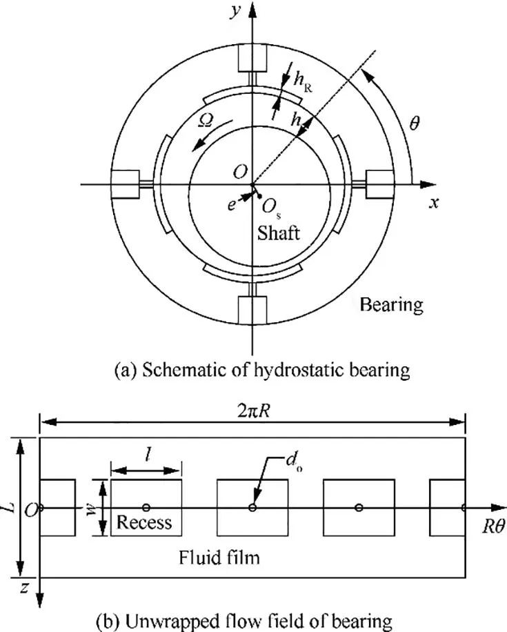
Fig. 1 Schematic of a hydrostatic bearing and the unwrapped flow field.
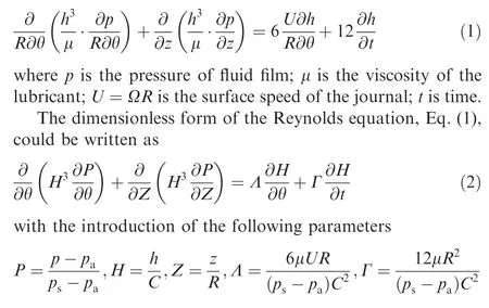
where P is the dimensionless form of pressure;psis the supply pressure; pais the ambient pressure; H is the dimensionless form of film thickness;C is the radial clearance of the bearing.
2.3. Perturbation analysis
As indicated in the Introduction, the mathematical perturbation technique is superior to the physical perturbation technique in terms of precision and calculation speed. The numerical method discussed in this paper is based on the mathematical perturbation technique. With the mathematical perturbation technique, the perturbations applied to the journal at an equilibrium position are small displacements (Δx,Δy)and velocities (Δ ˙x,Δ ˙y). In the coordinate system shown in Fig. 1, the first order Taylor expansion of the film thickness and the film pressure with respect to these small displacements and velocities could be written as

where H0and P0are the dimensionless film thickness and dimensionless film pressure in the steady-state, respectively;(ΔX,ΔY) and (Δ ˙X,Δ ˙Y) are the dimensionless form of(Δx,Δy) and (Δ ˙x,Δ ˙y), respectively; Px,Py,P˙x,P˙yare the dimensionless perturbed film pressure with respect to the dimensionless displacements and velocities.
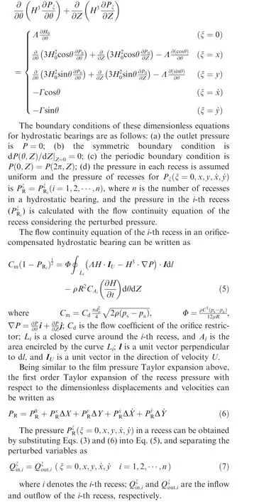
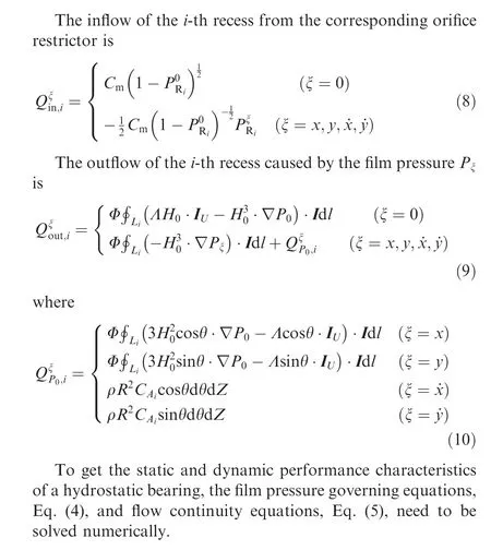
The equations for perturbed pressure could be derived by substituting the expansion of the film thickness and the film pressure into the Reynolds equation. By substituting Eq. (3)into Eq. (2) and separating variables with respect to each perturbed displacement and velocity, the perturbation equations are obtained5,6
3. Numerical method
3.1. Solution of pressure field
In this section,the process of the improved method in calculating the performance characteristics of incompressible laminar flow hydrostatic bearings is presented.
For incompressible laminar flow hydrostatic bearings, the equations in Eq. (4) are linear and then can be solved using the linear superposition principle. The solution of each equation in Eq. (4) can be written as

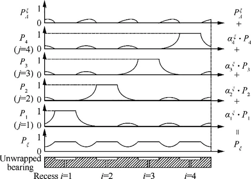
Fig. 2 A schematic illustration of the superposition of hydrostatic bearing film pressure.
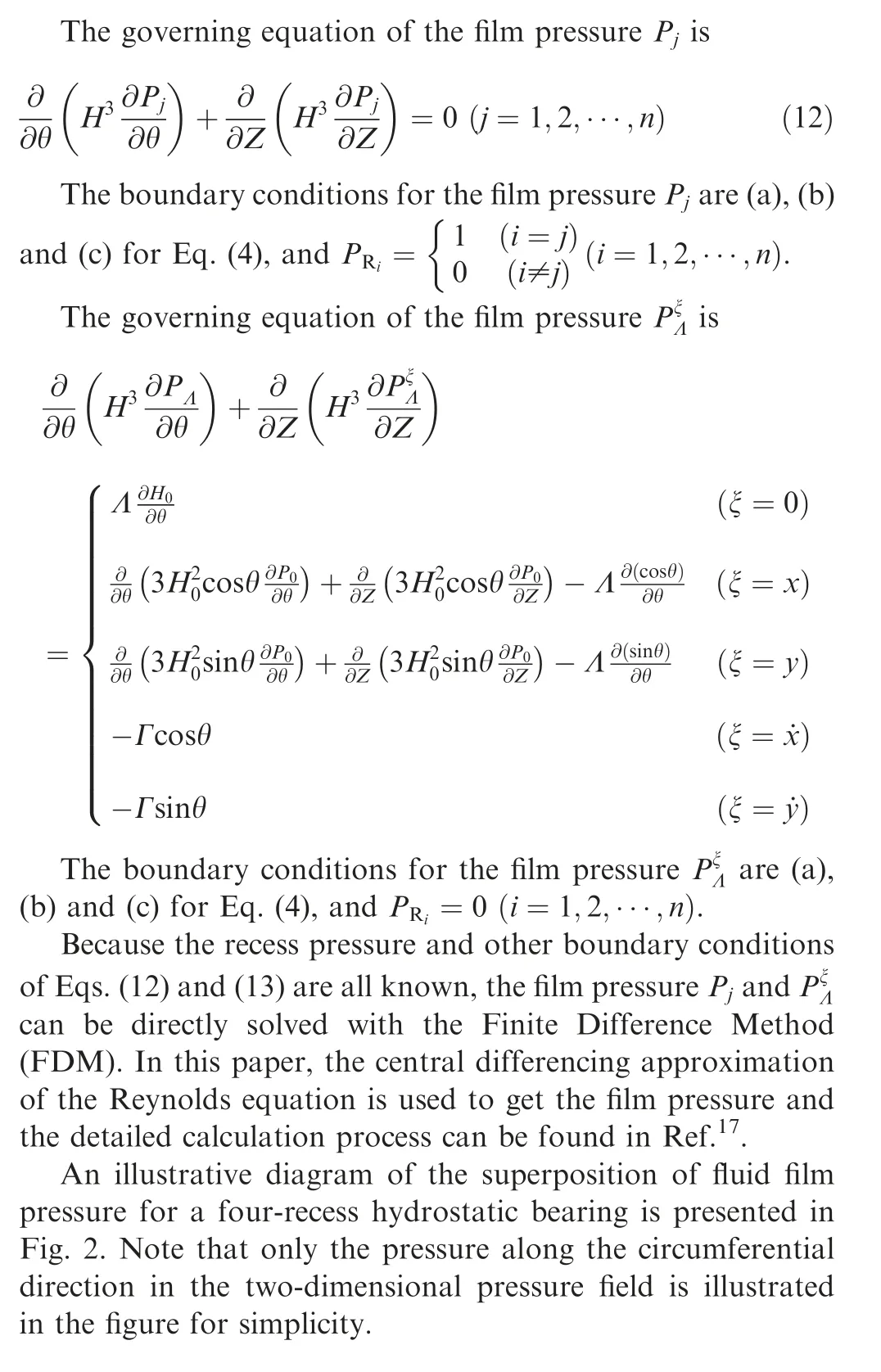
3.2. Solution of flow continuity equation
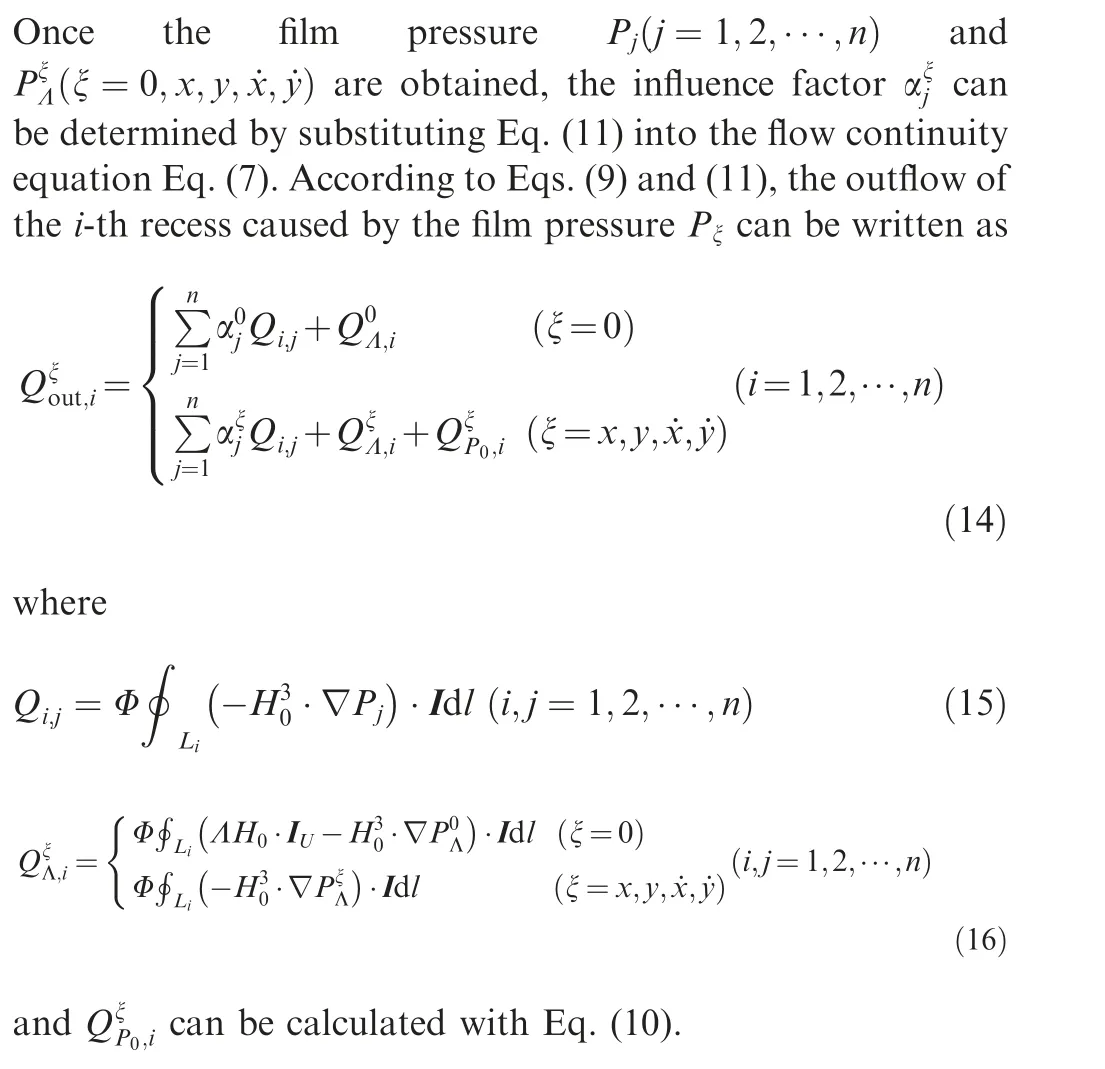
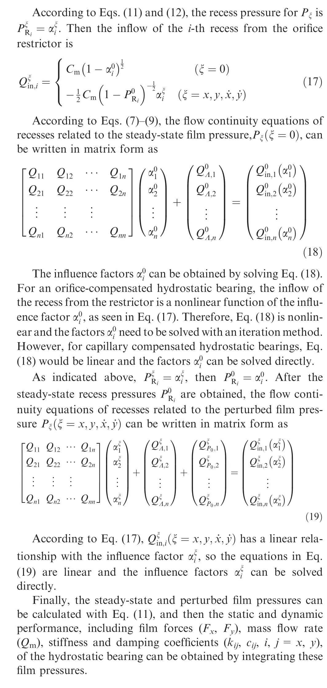
3.3. Comparison between two methods
The flow charts of the two methods, i.e., the conventional method and the improved method, for solving the Reynolds equation of hydrostatic bearings are presented in Fig. 3. For both methods,only the main procedures in solving the governing equations of hydrostatic bearings are presented. Note that the solution methods of the Reynolds equation with given recess pressures and other boundary conditions(i.e.,the procedures within the dotted line frames) in the two methods are identical. The main difference between the two methods lies in the processing of bearing recess pressures.
As seen in Fig.3,in the conventional method,the solving of the Reynolds equation and the solving of the flow continuity equations are coupled. The iterative loop for the film pressure and that for the recess pressures are nested. That is to say, if the pressure of any of the recesses is revised, the Reynolds equation needs to be re-solved. However, in the improved method, the nested iterative loops in solving the Reynolds equation and the flow continuity equations are uncoupled based on the linear property of the laminar flow Reynolds equation. In this way, the computational efficiency of bearing performance characteristics is improved significantly. And the difficulty of convergence in solving the recess pressures at high eccentricity ratios in the conventional method is avoided as well. With the improved method, the steady-state and perturbed film pressures can be obtained in a shorter time and the static and dynamic performance characteristics of a hydrostatic bearing can be easily calculated by integrating these steady-state and perturbed film pressures.
The numerical calculating process of the improved method can be described as follows. First, fluid film pressures are obtained by solving a set of Reynolds equations (Eqs. (12)and (13)) under given recess pressures and other boundary conditions using FDM method. Second, the influence factors of each recess pressure on the steady-state and perturbed film pressures are calculated by solving the equations(Eqs.(18)and(19)) derived from the flow continuity equations of the recesses. Finally, the steady-state and perturbed film pressures can be obtained using Eq.(11),the film pressure and influence factors calculated in the previous steps. Then, the film force,the stiffness and damping of the hydrostatic bearing can be calculated by integrating these steady-state and perturbed film pressures.
4. Results and discussion
4.1. Object description for calculation
In the following sections,the dynamic coefficients and stability characteristics of a water-lubricated hydrostatic bearing,which was designed by the authors to test hydrostatic bearing technologies for turbopumps, are calculated with the improved method under the laminar flow assumption. Some experimental results of the bearing tested on a test rig are presented and discussed as well. As shown in Fig. 1 (a), the bearing is a typical four-recess orifice-compensated hydrostatic bearing. The bearing test rig,as shown in Fig.4,has a symmetrical structure with the rotor supported by two identical test hydrostatic bearings. The rotor is driven by a gas turbine using high pressure nitrogen, and the lubrication water of the bearings is pressurized by high pressure nitrogen as well. The schematic of the bearing test system can be found in Ref.15. The main nominal geometric parameters and operating parameters of the hydrostatic bearing and the rotor are listed in Table 1.
As mentioned before,the improved method discussed in the above section is only applicable for linear Reynolds equation.So,in the calculation of the water-lubricated hydrostatic bearing, the density and the viscosity of the lubricant (water) are assumed to be constants and they are 998.6 kg/m3and 1005 μPa·s(293 K)respectively.Moreover,it needs to be noted that the orifice flow coefficient(Cd)of the bearing in Table 1 comes from the orifice mass flow experiment of the hydrostatic bearing conducted by the authors;the details about the experiment can be found in Ref.15.
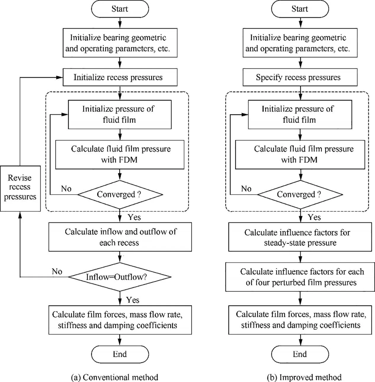
Fig. 3 Flow charts of two methods (only main procedures are presented).
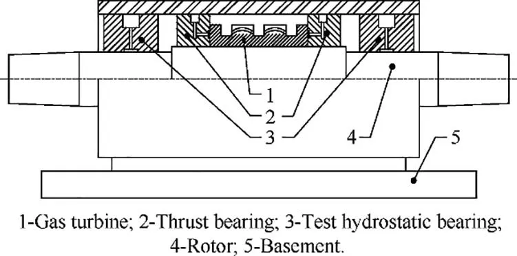
Fig. 4 Schematic of hydrostatic bearing test rig.
4.2. Computational efficiency of the improved method
Compared with the conventional method, the improved method is more time saving in theory. To show the computational efficiency of the improved method under the same conditions with other methods, the computation time taken by these three different methods (the physical perturbation technique, the conventional method, and the improved method)in calculating the eight dynamic coefficients of the waterlubricated hydrostatic bearing at the concentric position (i.e.,eccentricity ratio ε=e/C=0) is recorded and compared.These three methods are all developed by the authors with C#in Microsoft®Visual Studio 2010.Considering the symmetry of the flow field of the bearing shown in Fig.1(b),only halfof the flow field is calculated; the grid number used in the calculation is 60×20. The FDM is applied in solving the Reynolds equation with given recess pressure and other boundary conditions. With a same personal computer (Intel®CoreTMi3-380 M,RAM 4 GB),the computation time taken by these three different methods is presented in Table 2.
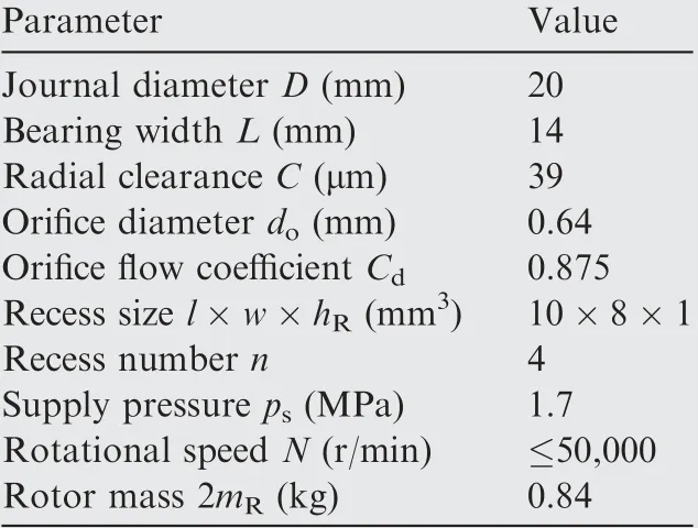
Table 1 Main parameters of hydrostatic bearing and rotor.
As shown in Table 2,in the row of‘‘Number of times”,the number before ‘‘×” means the number of the Reynolds equations to be solved, and the number after ‘‘×” means the number of iterations required, which is variable for different equations owing to the variation of operating parameters, to satisfy the mass continuity equation of the recesses. It can be seen that, compared with the physical perturbation technique,the conventional method based on the mathematical perturbation technique reduces the time for calculating the dynamic coefficients, whereas the improved method presented in this paper can further reduce the calculation time.In this example,the computation time of the improved method is approximately one-fourteenth of that of the conventional method.Only from the point of view of the data in Table 2,the computational efficiency improvement of the improved method does not make much sense. However, in optimization design or transient response calculation of hydrostatic bearings, where the solving of the Reynolds equation may be repeated thousands of times and the time consumed may be several hours,the application of the improved method could make much difference in saving calculation time.
4.3. Dynamic coefficients
As indicated in the Introduction, the improved method is an extension of a method used to calculate bearing static performance characteristics.14,15In this paper, the improved method can be used to calculate both the static and the dynamic performance characteristics of hydrostatic bearings. The load capacity and mass flow rate calculated with the improved method are in agreement with the corresponding numerical and experimental results in Ref.15, which verifies the effectiveness of the improved method in calculating bearing static performance characteristics.
In this section, only the dynamic coefficients (including stiffness and damping) of the water-lubricated hydrostatic bearing calculated with the improved method are presented and discussed. As a comparison, the dynamic coefficients calculated with the conventional method are also presented.The variation of stiffness and damping coefficients of the bearing with eccentricity ratio and with rotational speed are presented in Figs. 5 and 6 respectively. The solid lines with solid symbols in the figures represent the results obtained with the improved method and the dashed lines with hollow symbols represent the results from the conventional method.
As shown in Fig. 5, the stiffness and damping coefficients calculated with the improved method have a pretty good agreement with the results calculated with the conventional method based on physical perturbation technique. The maximum differences of the results between the two methods lie in the direct stiffness coefficients(kyy)and damping coefficient(cyy) at large eccentricity ratios, where the gradient of these coefficients are larger.These differences are mainly due to that the stiffness and damping coefficients calculated with the physical perturbation technique are easily affected by the perturbation amplitude of displacement and velocity.6It can be seen from Fig.5 that the direct stiffness(kyy)first increase and then decrease with eccentricity ratio. This phenomenon is mainly determined by the ratio of flow resistance between the orifice restrictor and the bearing clearance,15which is dependent on the geometric and operating parameters of a bearing.
The result in Fig. 5 indicates that the stiffness and damping coefficients of the hydrostatic bearing have a nonlinear relationship with eccentricity ratio. In the range of small eccentricity ratio, the variation of the stiffness and damping can be simply neglected. However, when the bearing is operating in a range of large eccentricity ratio as a result of large unbalance forces, the nonlinearity of the dynamic coefficients may have significant influence on the dynamic characteristic of the rotor-bearing system. The influence of the nonlinearity of bearing stiffness and damping coefficients on the dynamic response of the rotor will be discussed in Section 4.4.
As shown in Fig. 6, the stiffness and damping coefficients calculated with the two methods are almost the same. At the calculated eccentricity ratio, the rotational speed has almost no effect on the direct stiffness coefficients of the hydrostatic bearing; however it has significant effect on the cross stiffness coefficients. It can be seen from the figure that the cross stiffness coefficients have approximately a linear relationship with the rotational speed. Considering that the cross stiffness coefficient of fluid film bearing is a main factor leading to instability, the variation of cross stiffness coefficients with rotational speed should be paid enough attention in the dynamic performance analysis of rotor-bearing systems. The rotational speed has almost no effect on the damping coefficients of the hydrostatic bearing.
The results in Figs. 5 and 6 confirm the effectiveness and correctness of the improved method in calculating the dynamic coefficients of hydrostatic bearings.
4.4. Dynamic responses
As shown in the previous section, the dynamic coefficients have a nonlinear relationship with eccentricity ratio. To figure out the effect of the nonlinearity of stiffness and damping coefficients on the dynamic response of a rotor supported by the hydrostatic bearings, the unbalance responses of the rotor shown in Fig. 4 are calculated using both the nonlinear and the linear bearing dynamic coefficients models. In the calculation, the Jeffcott18rotor model is used for simplicity and the rotor-bearing system is simplified to a rigid rotor supported by two identical hydrostatic bearings. The simplified rotorbearing model is shown in Fig. 7.

Table 2 Computation time of different methods.
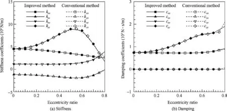
Fig. 5 Variation of dynamic coefficients with eccentricity ratio at N=30000 r/min.
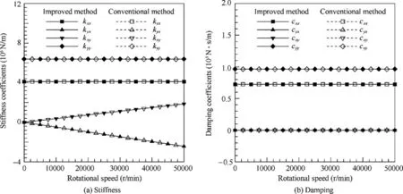
Fig. 6 Variation of dynamic coefficients with rotational speed at ε=0.3.
Considering the symmetry of the rotor-bearing system,only half of the system (half of the rotor and one hydrostatic bearing) is taken into account in the following analysis. The equation of motion for the rotor with unbalance forces can be written as

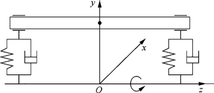
Fig. 7 Simplified rotor-bearing model.
where mRis half of the rotor mass; Fxand Fyare the film forces of the hydrostatic bearing; Wxand Wyare external static loads applied to the rotor,including the gravity of the rotor;euis the eccentricity of the rotor mass center,and Fu=mReuΩ2is the unbalance force.
In the linear dynamic coefficients model,the dynamic characteristic of the hydrostatic bearing is modeled with the stiffness and damping coefficients at the equilibrium position of the rotor under external static loads. And the film forces can be written as follows

where kijand cij(i,j=x,y)are the stiffness and damping coefficients of the hydrostatic bearing at the equilibrium position,respectively.
In the nonlinear dynamic coefficients model,the film forces are numerically calculated by solving the time dependent Reynolds equation (Eq. (2)) with the displacement and velocity of the journal at each time step during the whirling motion. In this way,the nonlinearity of stiffness and damping coefficients is taken into account in the calculation, although these coefficients are not explicitly used.
Fig. 8 shows the unbalance responses of the rotor-bearing system in cases with different static loads and unbalance forces applied to the rotor. The stiffness and damping coefficients used in the linear model and the corresponding equilibrium positions under different static loads are listed in Table 3.The minus sign in front of the static load indicates the load direction is opposite to the axis direction in Fig.1(a).In cases(a), (c) and (e), the unbalance force amplitude is Fu=12.4 N(eu=3 μm); in cases (b), (d) and (f), the unbalance force amplitude is Fu=24.8 N(eu=6 μm). In all cases, the supply pressure of water for the hydrostatic bearing is 1.7 MPa and the rotational speed is 30,000 r/min.
It should be noted that in Table 3 and Fig. 8, the displacements of the rotor are given in dimensionless form,and X and Y are the normalized horizontal and vertical displacements of the rotor respectively, X=x/C, Y=y/C.
In the calculation of unbalance response, the four-order Runge-Kutta method is used to solve the motion equations,Eq. (20), for the rotor. The initial positions of the unbalance responses are the equilibrium positions of the rotor under external static loads.
In Fig. 8, the solid lines are the results calculated with the nonlinear model and the dashed lines are the results calculated with the linear model.As shown in Figs.8(a),(c)and(e),when the journal whirls in a small eccentricity ratio range in cases with small unbalance force,the results calculated with the two models show a pretty good agreement.While when the journal whirls in a large eccentricity ratio range in cases with larger unbalance force,as shown in Figs.8(b),(d)and(f),the responses calculated with the nonlinear and the linear models show an apparent discrepancy.This is mainly due to the nonlinearity of the stiffness and damping coefficients,as seen in Fig.5.As shown in Fig.5,with the increasing of eccentricity ratio,the change rates of kyyand cyyversus eccentricity ratio are getting larger. The maximum difference of kyyin the calculated eccentricity ratio range is about 80%of the maximum value.
In Ref.4,it was concluded that the rotordynamic force coefficients have a weak dependency on the journal equilibrium position and hence the linear model should be adequate to predict the rotor-bearing system time response due to applied dynamic loads. The results in Figs. 5 and 8 indicate that the linear dynamic coefficient model is applicable for a hydrostatic bearing operating in a small eccentricity ratio range (ε <0.3-0.4)in cases with small rotor unbalance forces.However,if the journal whirls in a range of large eccentricity ratio (ε >0.3-0.4) in cases with large unbalance forces, the linear dynamic coefficients model will lead to larger errors.
It can be seen that the locus of shaft center in Figs.8(a)and(b) is a circle, while the locus in Figs. 8 (c), (d), (e) and (f) is approximately an ellipse. This anisotropic behavior is mainly due to the nonlinearity of stiffness and damping coefficients of the hydrostatic bearing19, although it is geometrically axially symmetrical.
To show the difference between the nonlinear and the linear unbalance responses clearly, the normalized vertical displacement (Y) in Fig. 8 (f) is additionally presented in time domain in Fig. 9 and presented in frequency domain in Fig. 10.
In Fig. 9, the responses of the two models show no apparent difference except that the amplitude calculated with the nonlinear model is a litter larger than that calculated with the linear model, whereas in Fig. 10 the difference is clear.As shown in Fig. 10, the frequency spectrum of the linear response has only one peak at the rotational frequency 500 Hz (30000 r/min) of the rotor, which is undoubtedly induced by the unbalance force. However, the spectrum of the nonlinear response has two peaks, one is at the rotational frequency and the other is at the double rotational frequency.That is to say, the double rotational frequency component is very likely induced by the nonlinearity of the dynamic coefficients of the hydrostatic bearing.
4.5. Stability analysis
Stability analysis is an important part to evaluate the dynamic performance characteristics of a rotor supported by fluid film bearings. The whirl frequency ratio is a commonly used parameter indicating the stability characteristic of a rotorbearing system. A smaller whirl frequency ratio means that the rotor-bearing system can safely operate at a higher rotational speed relative to the critical speed of the system. It is defined as the ratio between the whirl frequency and the rotational frequency of the rotor in the stability threshold state.Under a given operating condition, the whirl frequency ratio γstof a fluid film bearing is calculated as20

Fig. 11 shows the variation of the whirl frequency ratio with rotational speed at different eccentricity ratios. Because the whirl frequency ratio at a very low speed may be meaningless (i.e., γ2st<0 in Eq. (22)), only the values in the concerned rotational speed range are presented. The stiffness and damping coefficients used in calculating the whirl frequency ratio are calculated with the improved method.
As shown in Fig. 11, in the presented speed range, the whirl frequency ratio at the concentric position (ε=0) is almost a constant close to 0.5; however, in the eccentricity ratio range of 0.2-0.5, the whirl frequency ratio varies significantly. The variation of whirl frequency ratio of the hydrostatic bearing with rotational speed is different from that of a plain hydrodynamic bearing. Thus, the methods of predicting stability threshold speed for the two kinds of bearings should be different. Under a short bearing assumption, the dimensionless stiffness and damping coefficients of a hydrodynamic bearing are independent of rotational speed, and then the whirl frequency ratio at a specified eccentricity ratio is independent of rotational speed as well; it is a constant close to 0.5. Therefore, the stability threshold speed of hydrodynamic bearings can be directly predicted with the dimensionless stiffness and damping coefficients, as the method given in Refs. 17 and 20. However, for the hydrostatic bearing studied, as seen in Fig. 11, the whirl frequency ratios at ε ≥0.2 vary significantly with the increase in rotational speed. Therefore, the variation of whirl frequency ratio with both the eccentricity ratio and the rotational speed needs to be taken into account in calculating the stability threshold speed of hydrostatic bearings.
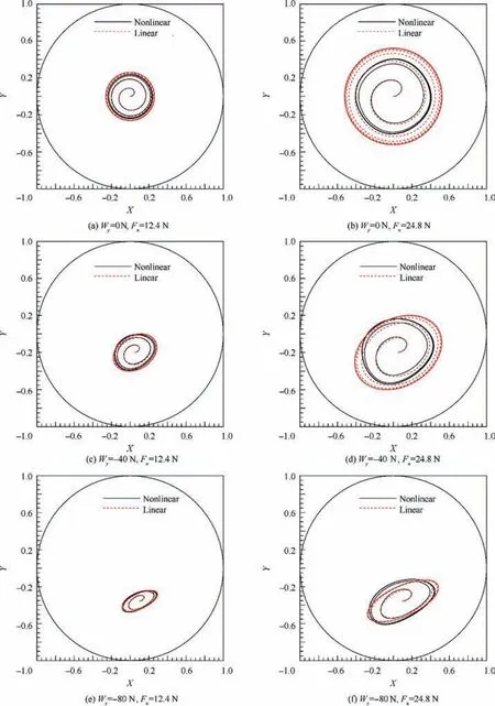
Fig. 8 Dynamic responses calculated with nonlinear and linear dynamic coefficients model in cases with different static loads and unbalance forces at N=30000 r/min.
The variation of whirl frequency ratio with speed in Fig. 11 also indicates that the hydrodynamic effect, a factor leading to instability, in the hydrostatic bearing plays a more and more important role with the increase in rotational speed. For the hydrostatic bearing studied,the whirl frequency ratio at a specified speed decreases with the increase in eccentricity ratio in the range of 0-0.5.

Table 3 Stiffness and damping coefficients used in the linear model (30,000 r/min).
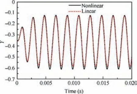
Fig. 9 Unbalance response in Fig. 8 (f) plotted in time domain.
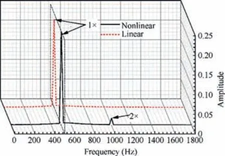
Fig. 10 Frequency spectrum of unbalance response in Fig. 9.
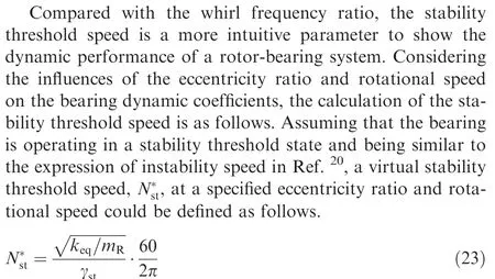
It should be noted that the virtual stability threshold speed is not the(actual) stability threshold speed of the bearing;it is only a reference value used to judge the stability state of the bearing.The virtual stability threshold speed can be calculated
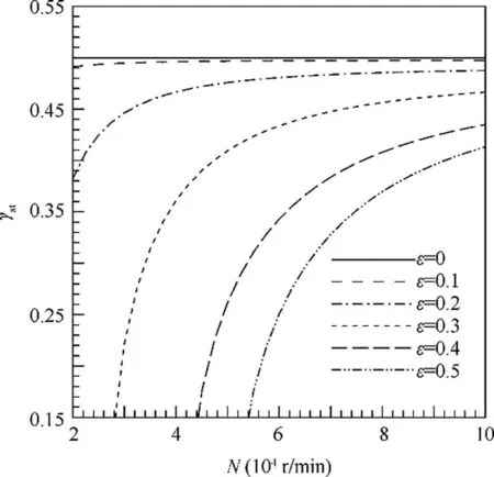
Fig.11 Variation of whirl frequency ratio with rotational speed.
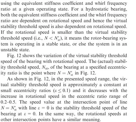
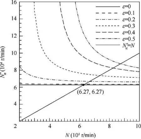
Fig. 12 Stability threshold speed at different eccentricity ratios.
From the series of intersection points of line N=N*stwith other lines in Fig.12,it can be known that the stability threshold speed of the hydrostatic bearing increases with eccentricity ratio in the calculated range. Considering that both the whirl frequency ratio in Fig. 11 and the virtual stability threshold speed in Fig. 12 at ε=0 are constant, the stability threshold speed of the bearing at ε=0 can be easily obtained with the stiffness and damping coefficients at a nonzero speed.Whereas, when calculating the stability threshold speeds at eccentric positions,the variation of the virtual stability threshold speed, as shown in Fig. 12, needs to be obtained firstly.Therefore, the calculation of the stability threshold speed at the concentric position (ε=0) is much easier than that at eccentric positions. Owing to its increasing with eccentricity ratio, the stability threshold speed at the concentric position(ε=0) can be conservatively seen as the highest speed that the bearing can operate stably.However,if more accurate stability threshold speed is needed and the bearing operates at ε ≥0.2, the variation of virtual stability threshold speed with rotational speed should be accounted. For the waterlubricated hydrostatic bearing under the studied condition,the stability threshold speed at ε=0 is 6.27×10⁴r/min Thus,it can be concluded that the stability threshold speed of the bearing is no smaller than 6.27×10⁴r/min, that is Nst-≥6.27×10⁴r/min.
It is known that the hydrostatic effect of a hydrostatic bearing becomes smaller with the decrease in eccentricity ratio. As shown in Fig. 11 and Fig. 12, with the decrease in eccentricity ratio and increase in rotational speed,the whirl frequency ratio and virtual stability threshold speed are becoming a constant,which is a feature of hydrodynamic bearings. This indicates that the dynamic characteristic of a hydrostatic bearing is becoming closer to that of a hydrodynamic bearing. The increase in the stability threshold speed with eccentricity ratio in the range of 0-0.5 indicates that the rotor-bearing system is more stable with the increase in eccentricity ratio from 0 to 0.5.This is consistent with the conclusion for plain hydrodynamic bearings that the stability of the bearing can be improved by increasing the operating eccentricity ratio of the journal in the bearing.17
4.6. Experimental verification
In order to validate the numerical results of the hydrostatic bearing, the four-recess bearing was tested with water on the test rig shown in Fig. 4.
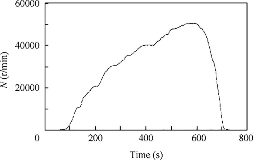
Fig. 13 Variation of rotational speed with time in a test.
The variation of rotational speed with time in a test is shown in Fig. 13. The vibration displacements of the rotor were measured and the waterfall diagram of the vertical vibration displacement is shown in Fig. 14. In the test, the supply pressure of water for the bearing is 1.7 MPa; the rotor is speeded up graduately and its maximum speed value is about 50,500 r/min.
As shown in Fig. 14, no half speed whirl (or subsynchronous vibration) is found in the whole tested speed range.That is to say, the hydrostatic bearing is operating in a stable state in the whole speed range. Accordingly, the stability threshold speed of the bearing under the test conditions is larger than the maximum operating speed, 50,500 r/min. This is consistent with the numerically predicted result that Nst-≥6.27×10⁴r/min and it also verifies the rationality of the designed working speed range of 0-50000 r/min. However, it should be noted that in spite of that no half speed whirl instability occurs in the working speed range,the rotor-bearing system may still suffer from a rub-impact failure caused by unbalance forces if the rotor is not properly balanced.
It can be seen in Fig.14 that three different frequency components clearly appear in the rotor vibration frequency spectrum. The rotational frequency component, which has the largest amplitude in the three, is undoubtedly partly, if not all, caused by the residual unbalance of the rotor. Except for the rotational frequency component, the other two are the double and the triple rotational frequency components. The frequency components in Fig. 14 are very similar to the frequency spectrum of the modified turbocharger with threelobe journal bearings in the stable speed range in Ref.21.According to Ref.22, double and triple rotational frequency components could be induced by the misalignment of a rotor or a looseness fault of the test rig; however, both of the two phenomena were not found during the test. The numerical results in Fig.10 shows that double rotational frequency component appears in the spectrum of unbalance response calculated with nonlinear bearing dynamic coefficient model. For this reason, it might be concluded that the nonlinearity of the dynamic coefficients of the hydrostatic bearing could induce double rotational frequency component in the dynamic response spectrum of the rotor-bearing system. Meanwhile,because many influence factors and parameters are neither considered in the numerical calculation nor measured during the test, the factors inducing the triple rotational frequency component are still not determined in this paper.
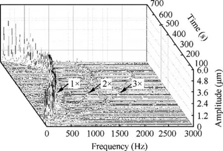
Fig.14 Waterfall plot of rotor vibration frequency spectrum in a test.
5. Conclusions
An improved method based on the mathematical perturbation technique for calculating the dynamic coefficients of hydrostatic bearings is presented. The stiffness and damping coefficients of a water-lubricated four-recess hydrostatic bearing are calculated with this method and compared with the results calculated with the conventional method. The unbalance responses of a rotor supported by the hydrostatic bearing are calculated with both the nonlinear and the linear bearing dynamic coefficients models. The stability characteristic of the rotor-bearing system are analyzed and compared with the experimental results. The improved method can be used to evaluate the static and dynamic performance of hydrostatic bearings efficiently. The dynamic performance of the bearing presented could contribute to a better understanding of the characteristics of water-lubricated hydrostatic bearings.
The conclusions can be summarized as follows.
(1) In contrast with the conventional method,the improved method has no difficulty of convergence at high eccentricity ratio; it ensures the accuracy of the calculation results of dynamic coefficients and shortens the calculation time. However, the improved method can only be applied to laminar flow hydrostatic bearings.
(2) The dynamic characteristic of the hydrostatic bearing operating in a small eccentricity ratio range (ε <0.3-0.4) can be modeled with linear stiffness and damping coefficients. Whereas, in a large eccentricity ratio range(ε >0.3-0.4), the linear dynamic coefficients model will lead to larger errors, owing to the nonlinearity of the dynamic coefficients. Moreover, the nonlinearity of the dynamic coefficients could induce double rotational frequency component in the rotor unbalance response frequency spectrum.
(3) The stability threshold speed of the hydrostatic bearing increases with eccentricity ratio in the calculated range of 0-0.5; thus its value at the concentric position(ε=0) can be conservatively seen as the highest speed that the bearing can operate stably.
(4) The rotational speed has little effect on the direct stiffness and damping coefficients of the hydrostatic bearing;however it has significant effect on the cross stiffness coefficients. With the decrease in eccentricity ratio and the increase in rotational speed, the whirl frequency ratio is approaching a constant and the dynamic characteristic of the hydrostatic bearing is becoming closer to a hydrodynamic bearing.
 CHINESE JOURNAL OF AERONAUTICS2020年8期
- CHINESE JOURNAL OF AERONAUTICS的其它文章
- Structural dynamic responses of a stripped solar sail subjected to solar radiation pressure
- Rotor airfoil aerodynamic design method and wind tunnel test verification
- A heuristic cabin-type component alignment method based on multi-source data fusion
- Effect of curing condition on bonding quality of scarf-repaired composite laminates
- Influence of uniaxial tensile pre-strain on forming limit curve by using biaxial tensile test
- Influence of non-equilibrium reactions on the optimization of aerothrust aeroassisted maneuver with orbital change
