General optimal design of solar-powered unmanned aerial vehicle for priority considering propulsion system
Xinhua LI, Kaijun SUN, Feng LI
a School of Aeronautic Science and Engineering, Beihang University, Beijing 100083, China
b CH UAV Technology Co., Ltd, China Academy of Aerospace Aerodynamics, Beijing 100074, China
KEYWORDS Aircraft design optimization;General design technology;Route analysis;Solar-powered;Unmanned aerial vehicle
Abstract This paper describes the general optimization design method of Solar-Powered Unmanned Aerial Vehicle which priority considering propulsion system planning.Based on the traditional solar powered aircraft design method, the propulsion system top-level target parameters which affect the path planning are integrated into the general optimization design. According to the typical mission requirements of Solar-Powered Unmanned Aerial Vehicle, considering the design variables such as wing area, aspect ratio, design mission date and so on, the general optimization is carried out with the minimum aircraft weight as the optimization objective. The influence of wing area and aspect ratio on the optimal design results is analyzed and compared with the traditional design method. The results show that the general design method of Solar-Powered Unmanned Aerial Vehicle for priority considering propulsion system can greatly reduce the electricity demand of energy storage battery, greatly reduce the aircraft weight of Solar-Powered Unmanned Aerial Vehicle.
1. Introduction
Near-space Solar-Powered Unmanned Aerial Vehicle(SPUAV) is a kind of Unmanned Aerial Vehicle (UAV) that uses solar energy as the power source of aircraft to realize long-time cruise at high altitude. It has the characteristics of wide space coverage, long-endurance, low operation cost,and fast response. It is an ideal platform for regional communication, relay, and reconnaissance. So, it is also called a stratospheric satellite.
Due to the special energy sources and mission requirements of SPUAV in the near space,the design method is quite different from that of the traditional aircraft, mainly as follows:
Firstly,the SPUAV may cruise in the air for several months at a time. Generally, the design method ignores the effect of climb performance and takeoff performance but pursues the cruise efficiency of high-altitude.
Secondly,the energy source of SPUAV is solar energy.The design method does not consider the fuel consumption of the aircraft cruising,but the energy balance between day and night is considered.
The existing design methods of SPUAV are mainly a simple comprehensive of four vital elements: lift balance, thrust-drag balance, energy balance, and power balance. However, the energy density of the energy storage battery often fails to meet the design expectations, and the design results often cannot satisfy the extreme endurance requirements of the SPUAV.Many experts and scholars are aware of the strong coupling between route planning and energy requirements,and optimize the flight path to extend the duration of SPUAV.1-4And they propose the use of day-climbing and night-descending flight strategy.5This strategy enables the day-and-night cruise of SPUAV without using energy storage batteries at all.6Some experts and scholars put forward the aircraft general design method which is parallel to the general parameter optimization and route optimization. However, as the SPUAV route optimization usually adopt the pseudo-spectral method,7,8Bolza optimal control problem, HP-adaptive update method, etc.,which belongs to a continuous optimization problem, and the general optimization design usually use feasible region,genetic algorithm and particle swarm optimization method,9-12which belongs to a discrete point optimization problem.There is a great gap between the two kinds of optimization problems. Some experts at home have discussed the influence of flight altitude, energy, and reliability on the design of SPUAV, but no improvement on the design methods of SPUAV.13-15
Based on the analysis of flight dynamics of SPUAV, this paper summarizes the basic optimization rules of route planning,extracts the top-level target parameters of the propulsion system as the key characteristic parameters of the general optimization design, and optimizes the general parameters by using response surface method. This optimization avoids the complex coupling calculation between trajectory optimization and general parameter optimization.
2. General design method
The SPUAV includes solar cells,energy manager,energy storage battery,propulsion system, structure, payload, and avionics. Its design method is based on two simple balances, the force balance, and the energy balance.
The force balance involves SPUAV weight, aerodynamics force,and thrust,as well as the flight dynamics analysis,which are represented by the black arrow in Fig. 1.
During the day, depending on the solar irradiance and elevation in the sky, the solar cells convert light into electrical energy. The power obtained is used firstly to supply the propulsion system and the onboard electronics, and secondly to charge the battery with the surplus of energy. During the night,as no power comes from the solar cells,the battery supplies energy to the propulsion system and onboard electronics until the next morning. The input and output of energy are represented by the blue arrow in Fig. 1. The energy balance is the balance between energy obtained by solar cells and energy needed by the propulsion system and onboard electronics.
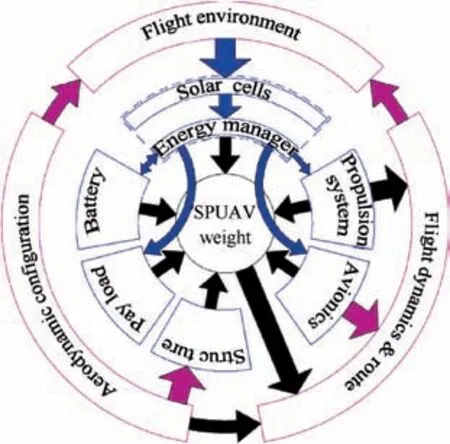
Fig 1 Subsystem and discipline coupling diagram.
The coupling of the subsystems and disciplines in addition to the force balance and energy balance are also shown by the pink arrow in Fig. 1.
2.1. Force balance
2.1.1. Weight prediction models
The total weight of SPUAV WTotalis the sum of the weight of SPUAV systems, including structure weight WStruct, solar cell weight WSolar, energy storage battery weight WBattery, propulsion system weight WProp, energy manager weight WManager,avionics weight WAvionics, and mission payload weight WPayload.

The empirical equation for Heliplat is cited in the weight assessment of the structure system, and the structure weight is estimated in a parametrical way as a function of the number of boom tails N, reference area S and aspect ratio AR.16

The solar cells are interconnected electrically and then encapsulated between two non-reflective transparent layers.Thus, the final calculation of the weight of the solar cell must take the cells and this encapsulation into account.This is done in the following equation where kSolarrepresents the sum of the surface density of the solar cells and the encapsulation respectively, and SSolarrepresents the required surface covered by solar cells.16

Concerning the battery, its weight is directly proportional to the energy it needs to store QBatteryand inversely proportional to its weight-energy ratio kBattery.16

The propulsion system is composed of four subparts: control electronics, motor, gearbox, and propeller. Looking at the past solar-powered aircraft designs, the weight of the four parts is assumed to have a linear relationship with power output, and all the parts have their power densities and efficiencies. To consistent in the system, it takes the maximum continuous power input of motor PMax.Propinto considering,and the constant kPropis used to predict the weight of the propulsion system:

The energy manager is used mainly for two applications.First, it is required to adapt the voltage of the solar cells so that they provided the highest power possible. Second, it is required to optimize the voltage and current output to the subsystem, such as the propulsion system and avionics. Base on the application of the system, the weight is proportional to the maximum power with a ratio of kManager, the maximum powered of the system is directly given by the maximum power output of the solar cells PMax.Solar.

The weight of the avionics and payload does not depend on the size and power of other systems. They are defined at the beginning of the design.
2.1.2. Propeller aerodynamics
For a propeller,it is assumed that there is a point at r radius of a propeller, where the blade element efficiency is the same as that of the propeller.Thus,the performance of the whole propeller is represented by the blade element at that point, and this simple evaluation method of propeller is named Simple Blade Element theory (SBE).
The angle between the incoming airflow and the rotating plane is as follows:17

Where ω is the angular velocity of the propeller, and ω=2πn, n is the propeller rotation speed, the velocity of incoming flow is V. Take the advance ratio J=V/nD to the formula, it has

D is the diameter of the propeller,and k is the relative position of this point on the propeller diameter, it has k=2r/D.The lift coefficient of the blade element is CLp, and the drag coefficient is CDp, and the coefficient can be calculated from the previous aerodynamics model which used for aircraft.The drag-lift angle of the propeller blade is γ, and it has17
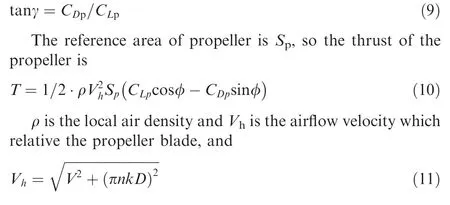
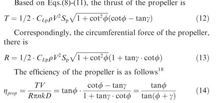
According to the above equations,the change of a propeller efficiency with the altitude and advance ratio is shown in Fig. 2, H stands for flight altitude. To verify the accuracy of the SBE theory,the result is compared with the Standard Strip Analysis(SSA).18The black line in the figure is the result of the SSA method, and the blue line is the result of SBE. It can be seen that the result of the SBE will slightly deviate after the optimal advance ratio, and the results of the two methods match well on the whole. The SBE method can effectively reflect the change of propeller efficiency under various working conditions.
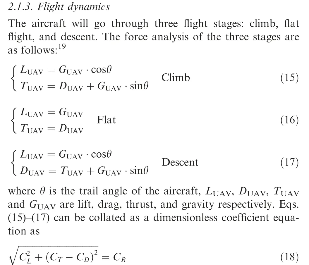
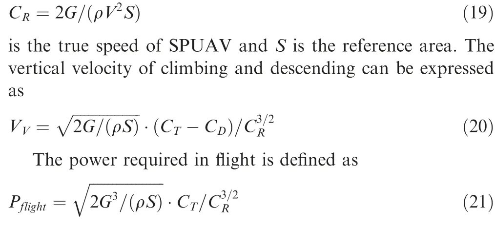
where CL, CDis the lift coefficient and drag coefficient of SPUAV,and the relationship of the two parameters are shown in the Appendix. CRis the gravity coefficient of the aircraft,and
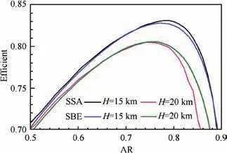
Fig 2 Variation of propeller efficiency with advance ratio at each height.
2.2. Daily electrical energy balance
The energy that is collected during a day from the solar cells must be equal to or higher than the electrical energy needed by the aircraft.
2.2.1. Daily solar energy obtained
The obtained solar energy at a certain moment is as follows.17

The calculation methods of solar intensity at a given height SIhand solar altitude angle α are shown in the Appendix. The efficiency obtained for solar cell ηSolarand the efficiency of the DC/DC convert by the energy management system ηManagerrepresent. It is recognized that the cambered airfoil, installation angle of wings and attitude angle of aircraft can affect the absorption of solar irradiance, and a flat disposition of solar panels is taken into the design method, the definition of the surface covered by solar panels is changed, and SSolaris redefined as the projection of the solar panels on a given plane. Correspondingly, kSolarshould make an adjustment,which will be a little larger than the real value.
The solar energy obtained in a day is
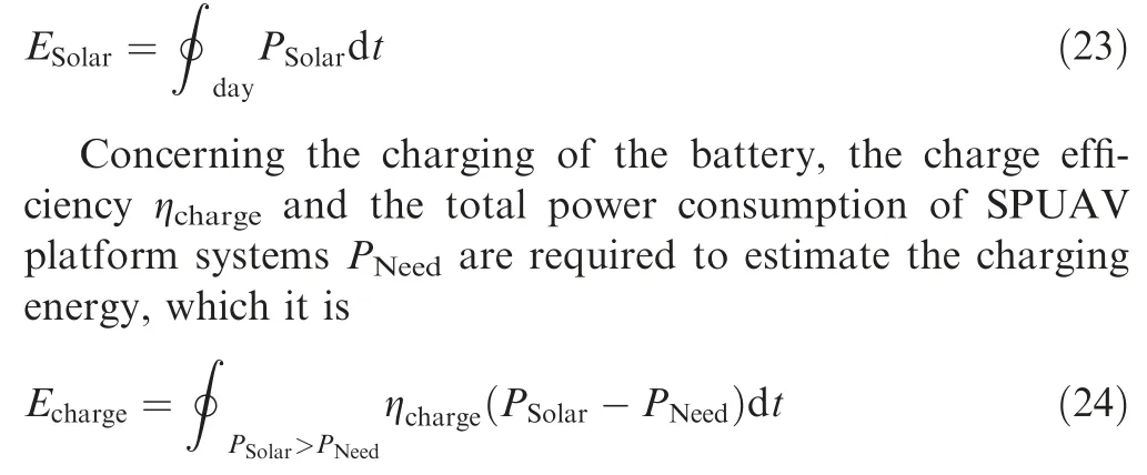
The total power consumption of the SPUAV platform includes the propulsion system, avionics, and payload. The power required for avionics PAvionicsand payload PPayloadis fixed, and consider the line loss rate and the voltage of these two elements should be changed, the efficiency ηbecmust be used;the power input the propulsion is PProp.This leads finally to the total electrical power consumption of:

2.2.2. Daily electrical energy required
The daily electrical energy required can be separated for two parts: solar power is above the total power required and solar power is below the total power required. At dusk and dawn,when the solar power is below the total required power, both sources,i.e.the solar cells and the battery,are used.The switch from one source to the other is progressive.The calculation of daily energy consumption uses the total power consumption and considers the charge ηchargeand discharge efficiency ηdchargeof the battery for the night period. If just calculate the energy comes from the battery, not from the solar panels,it is as follows.
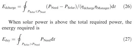
The charge cycle efficiency of the battery and the energy come from the solar panels when the solar power is below the total required power. The daily electrical energy required is as follows.

2.3. Flight strategy
Flight path affects the energy input and output of SPUAV,so an appropriate flight strategy can greatly reduce the energy required in night.The development of the intelligent flight control system also makes it possible to optimize the energy input and output of SPUAV.20,21
The power consumption of the propulsion system takes the efficiency of the motor ηmotand propeller ηpropinto account,the efficiency of the motor has considered the impact of the gearbox and electronic controller.

It could suppose the aircraft climbs from an altitude for a period tcin the day time and then descends to the original altitude in a period tgin the night. If vcrepresents the climb rate and vgrepresents the descent rate, this progress can be expressed as

The power required of the propulsion system from the source of the solar panel in the climbing process is Pc, and the power required of the propulsion system from the source of the solar panel in the descent process is Pg. The average power required of the propulsion system from the source of the solar panel in the whole process is

If the power of this process is considered to be equal or smaller than the average power from the solar panels which required for a level flight in the same state, and Pdrepresents the power required from the solar panels for a level flight in day time,Pnrepresents the power required from the solar panels for a level flight in night.

The power required from the solar panels Pc,Pg,Pd,Pncan be expressed by the power required in flight Pflight, the efficiency of the propeller ηprop, the charge and discharge efficiency of the battery ηcharge, ηdcharge, the efficiency of the motor ηmotand the efficiency of the energy management ηManager.
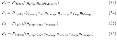
According to Eqs.(32)-(36),and take the expression of vertical velocity replaces the time expression, the equation which compares the average power of two methods is changed as follows.

When the aircraft cruises by using the minimum power, it has min(PProp)=min(CD/CR3/2), the corresponding point on the lift-drag ratio curve is the best cruising point. The best cruising point changes little when the aircraft climbs or descents, and the amplitude of the change is less than the control accuracy of the aircraft attitude, so it can be considered that the best cruising point of climb, descent and flat is the same,it has CD.g=CD.c=CD.l=CD.opt.Besides,the lift-drag ratio of SPUAV is so large that the thrust coefficient and drag coefficient has little effect on the coefficient CR,it can seem as CR.c=CR.g.In this way,Eq.(37) can be considered as a compare of the slope of two strings which located on the curve of the input power of propeller varying with the thrust coefficient,and the formula of the slope is shown below.

Fig. 3 shows the curve of the input power of the propeller varying with the thrust coefficient, as well as the point determined by the thrust coefficient and input power of the propeller for level flight. The slope of the string which connects with a larger thrust coefficient represents kc, and the other string represents kg.
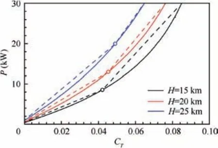
Fig 3 Input power of propeller varying with thrust coefficient.

According to Eq. (21), it can be obtained the relationship between the thrust coefficient and the input power of the propeller by introducing the propeller efficient, which is shown in Eq. (40). If the parameter G, ρ, S, ηprop, CRare constant, the curve in Fig. 3 should be straight. Because the propeller efficiency is affected by power factor and advance ratio,13the curve of the input power of the propeller varying with the thrust coefficient is a concave curve, the slope kcwill larger than the slope kg.It can be said that the curve slope characteristic in Fig. 3 is an inherent characteristic of the propeller whose design point is the night cruise point of the SPUAV.The better the design of the propeller, the closer the curve is to a straight line.
The difference of the input power between the aircraft climb and descent means that the requirement of energy battery is reduced. The closer the value at both ends of the inequality, the smaller the requirement of the energy battery.When the equal sign of the inequality is established, the requirement of the energy battery is minimum. Considering the curve is continuous, the solution of the equation is not unique, and the bigger the input power of sliding, the bigger the input power of climbing.Besides,the weight of the propulsion system is approximately linear with the input power, so the smaller the input power, the better. Comprehensive the weight of the energy battery and the weight of the propulsion system, when the input power for sliding is zero, the requirement of energy battery and the input power for climbing are both minimal.
The requirement of the energy battery reduces.The aircraft weight will certainly reduce. Affected by the reduction of the aircraft weight, the point of the thrust coefficient for a level flight will move slightly to the left, and the amount of the movement is hard to determine, this movement makes the equation difficult to solve.
To solve this problem, the input power of the propeller when the aircraft climbing is used as a design variable in the design. The aircraft climbs with this power when the energy from the solar panels exceeds the minimum energy requirement of aircraft. The aircraft descends with no power in the night. Under this flight strategy, the weight of the aircraft is calculated.Compare the weight of aircraft under various input power, the optimal power is obtained.
When the maximum power available climbing is a foregone conclusion,there is another way of thinking when just considering the descent strategy of the SPUAV.It is assumed that the energy consumption of the flight strategy which includes a low power descent and cruise at the mission altitude is better than the flight strategy which includes powerless descent and cruise at the mission altitude. The equation described is as follows.

The parameters Pg.1, Pg.2represents the power consumption in descent, which Pg.2stands for powerless descent, and it is zero. Pnrepresents the power for cruising at mission altitude. tg.1, tg.2, tn.1, tn.2represent the duration of each phase, it has tg.1+tn.1=tg.2+tn.2. Considering that the vertical velocity vg.1of low power descent is greater than that vg.2of powerless descent, and vg.1tg.1=vg.2tg.2, so it has tg.1>tg.2.According to the flight dynamics, take the expression of vg.1,vg.2into the equation, Eq. (41) can be changed to

This equation is also regarded as a compare of the slope of two strings which located on the curve of the input power of propeller varying with the thrust coefficient. It means that there is a point in the area where the flight altitude is greater than the mission altitude and the power is lower than the power required for the cruising at the mission altitude, and the slope of the string which connects the point and the cruising point at the mission altitude is greater than the slope of the string which connects the powerless point and the cruising point at the mission altitude.
According to the curves in Fig.3,it has two characteristics,one is a concave curve, the other is rotates curve which is approximately around the powerless point with the change of the altitude. It can be judged that the point required above maybe exist, but the flight altitude of the point will be quite close to the mission altitude. At this condition, the existence of this point is meaningless.
It is considered the efficiency of the motor and gearbox are not affected by working power and flight altitude, and it is a fixed value.The curves shown in Fig.3 reflects propeller working characteristic, when the efficiency of the motor and gearbox change with the input power, it also reflects the efficiency characteristics of the motor and gearbox.To be precise, the SPUAV flight strategy is determined by the propulsion system characteristics. Therefore, the general design method combined with trajectory planning is a general design method that priority considering the propulsion system.
3. General design process
The general optimization design flowchart is shown in Fig. 4.Three parts of the parameters are required at the start of the design: system parameters, mission parameters, and design variables. The system parameters are constant values, which mainly include the characteristic parameters of subsystem,disciplines,and mission,such as ηSolar,kSolar,ηcharge,etc.Mission parameters usually include endurance (flight time), latitude,minimum flight altitude, payload weight, and power, etc.Design variables are the reference area,the aspect ratio of aircraft and target altitude. System parameters and mission parameters are shown in the tables below (Tables 1 and 2).
During a mission cycle of SPUAV, the maximum solar radiation intensity of days and the sunshine time of days are changing. The sunshine time and the solar radiation intensity of the mission start and end are usually similar, the solar energy of these days can be obtained in theory is minimum,and any of them can be used as a design point. If the performance degradation and loss of the solar cells and energy battery are considered, there is no doubt that the design point should choose the mission end date. There is an unusual situation, the endurance of the mission is more than one year,choose the date that the solar energy can be obtained in theory is the minimum if there are two days and considering the performance degradation and loss of solar cells and energy battery, choose the day later.
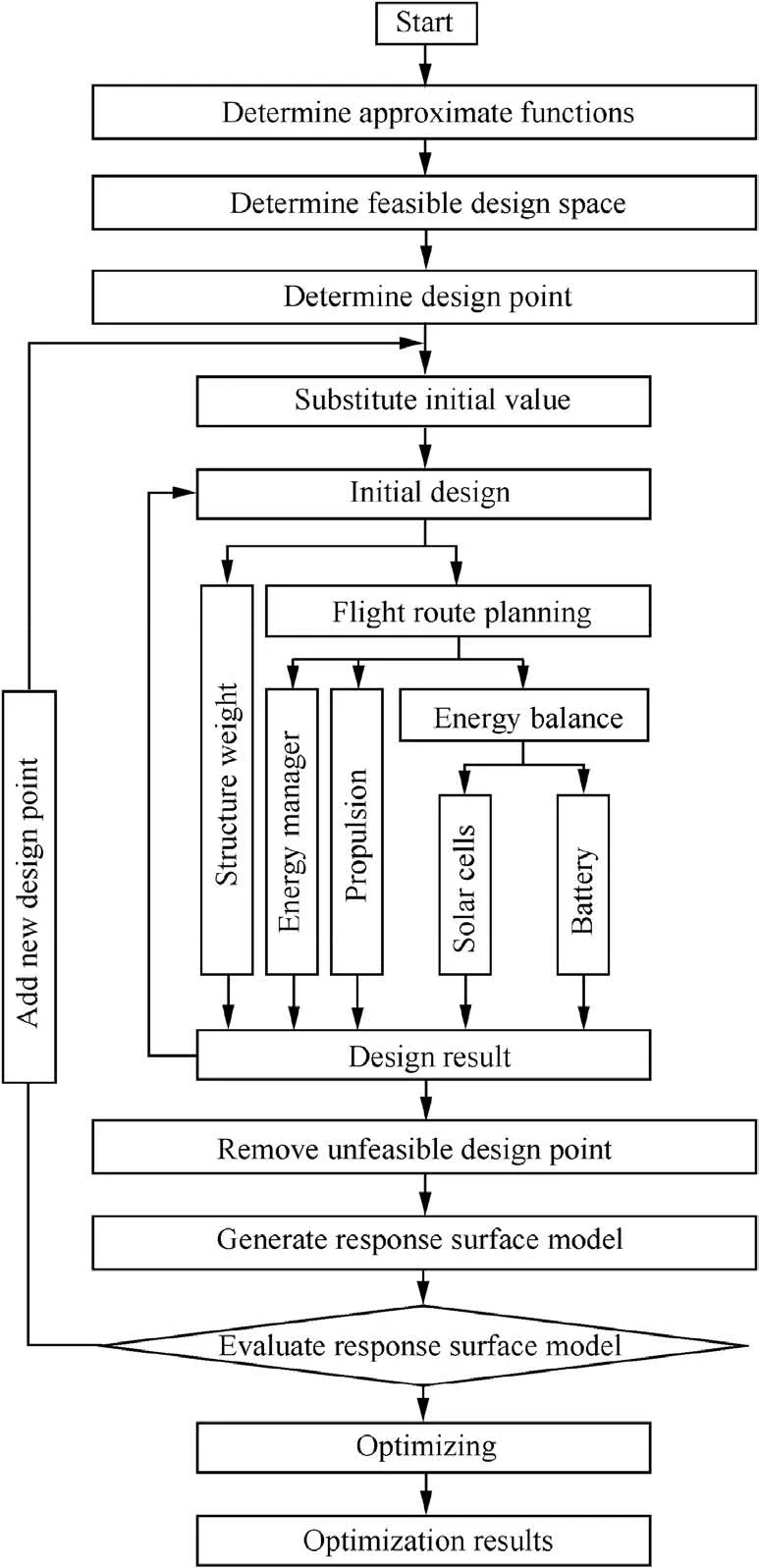
Fig 4 General optimization design flowchart.
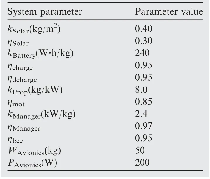
Table 1 Typical system parameters of SPUAV.
According to the conclusion of flight strategy analysis, the input power of the propulsion system should be taken as a design variable. Due to the unknown of the aircraft weight,to avoid the condition that the initial value of input power less than the requirement of the input power when the aircraft flew at the lowest mission flight altitude,the target altitude is introduced as a design variable, and then according Eq. (21) and Eq. (29) to calculate the input power of propulsion system.Compared with the input power, the target altitude is more intuitive and suitable as a design variable.
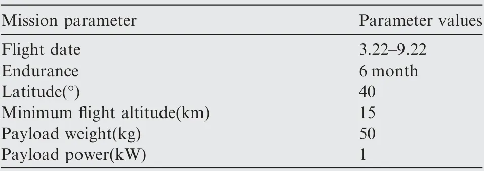
Table 2 Typical mission parameters of SPUAV.
According to the design variables and system parameters,the structure weight and the aerodynamic performance can be determined. Aerodynamics performance combines with the aircraft weight, the power requirement of the propulsion system can be calculated. On this basis, the flight track can be calculated,as well as the state parameters of the subsystem,such as ESolar, Echarge, Edcharge, PMax.Solar. Based on these quantities,the weight of the energy battery WBatteryand energy management WManagercan be calculated directly, SSolaris related to the initial iteration value and is calculated as follows.

The sum of the weight of subsystems WTotaland SSolarare iterated until the iteration values meet the convergence criteria.
4. Optimum design and analysis
According to the principle of central composite design, this paper takes the reference area, aspect ratio and target altitude as independent variables, SPUAV weight as response value,and makes response surface analysis of three factors and three levels.22The initial value range of the three factors is reference area 100 m2-400 m2, aspect ratio 10-40, target altitude 18 km-33 km.There will be a divergence of some test points in the initial value space.It is necessary to shrink the range of three factors to the existing optimal test value. This can also improve optimization accuracy. The spatial change of value range is shown in Fig.5. As a comparison, the response surface model is also used to obtain traditional design results. The comparison of the results of the two design methods can intuitively reflect the difference between the two methods.
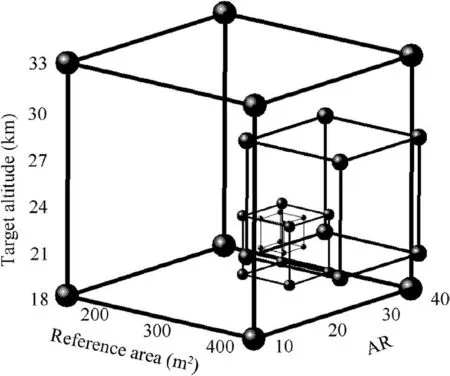
Fig 5 Spatial change of three variables.
Optimization design variables and results for the two methods are shown in Table 3. The reference area and aspect ratio of the two methods have no great difference and the method which including the target flight altitude in the design variables has a little smaller reference area and a little larger aspect ratio.The aerodynamics layout of SPUAV determined by the optimization results is shown in Fig. 6.
Judging from the design results, the solar cells area of the two methods also have no great difference, but the aircraft weight varies greatly. The aircraft weight of the new method is 8.7%less than the aircraft weight of the traditional methods.
The weight of the subsystems is shown in Table 4, and the proportion of the subsystems is drawn in Fig. 7. Due to the increased power requirement of the propulsion system and the reduction of the energy storage requirement, the weight of the propulsion increase and the weight of battery decrease in the new method.Viewed from the proportion of the subsystem weight, the proportion of propulsion system, solar panels and structure have been enhanced,and it means the sensitivity of these three subsystem parameters which associated with the weight of the subsystem are increased; the proportion of energy battery has been reduced, the sensitivity of weightenergy ratio decreases, and due to the proportion of the battery is still ranked first in the proportion of each subsystem,the importance of weight-energy ratio is premier.
Comparing the energy obtained from the solar panels and the energy required in night of the two methods, the energy obtained from the solar panels in the new method increase significantly, 1.9% due to the slightly increase of the solar cells,and the rest 3.8% due to the increase of the flight altitude in the sunshine. The energy required in the night in the new method decreases, 8.7% due to the decrease of the aircraft weight, and the rest 14.4% due to the flight strategy. The power obtained from the solar cells and the power consumed with time in both methods is shown in Fig. 8.
The altitude track is driven by the flight power which is shown in Fig. 9. The electricity of the battery is shown in Fig. 10. For the new method, when the power obtained from the solar panels equals the power requirement of the propulsion system during night cruise and the power requirement of avionics and payload, the energy battery begins to disconnect the energy communication until the power obtainedgreater than the maximum sustainable power input of the propulsion system and the power requirement of avionics and payload. During this period, the climbing rate of the aircraft increases gradually from 0, and the slope of the altitude curve increases gradually from the minimum flight altitude,the electricity of the battery remains at 0.The power obtained continues to grow, the input power of the propulsion system maintains the maximum sustainable value, the surplus power charges the energy battery. And the electricity of the energy battery increase. With the increase of flight altitude, aerodynamic performance of aircraft and an air density decrease,the climbing rate gradually decreases to 0, and the slope of the altitude curve decreases gradually to 0.
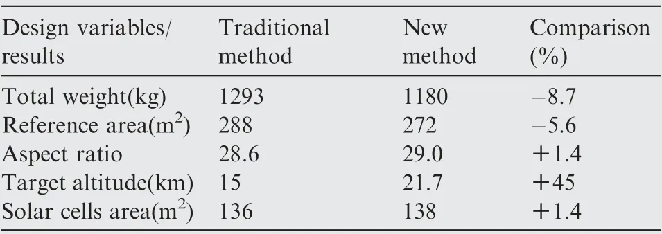
Table 3 Optimization design variables and results of the two methods.
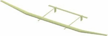
Fig 6 Aerodynamics layout of SPUAV.
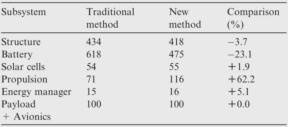
Table 4 Weight of subsystems (Unit:kg).
When the power obtained from the solar panels less than the maximum sustainable power input of propulsion system and the power requirement of avionics and payload,the power input to the propulsion system will decrease with the power obtained,the aircraft began to descend and the descending rate increases gradually from 0,the energy battery begins to disconnect the energy communication and the electricity of the battery remains at its maximum value. Until the power obtained less than the power requirement of avionics and payload,there is power supplied from the energy battery to the avionics and payload.The propulsion system keeps no power input until the aircraft descend to the minimum flight altitude. During this period, with the decrease of flight altitude, aerodynamic performance of aircraft and air density increase, the sliding rate gradually decreases to 0, and the slope of the altitude curve increases gradually to 0.
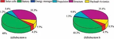
Fig 7 Proportion of subsystems.
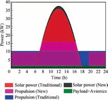
Fig 8 Power absorption and consumption of SPUAV.
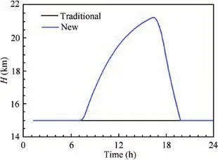
Fig 9 Flight altitude history of SPUAV.
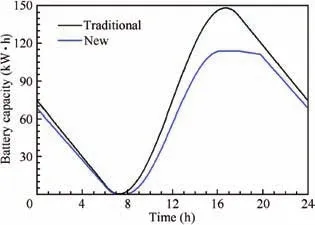
Fig 10 Electric quantity of SPUAV.
For the traditional method, the changes in flight altitude and the electricity of the battery are much simpler. The flight altitude is constant at the minimum altitude, the electricity curve only has two extreme points. When the power obtained from the solar panels begins to exceed the power requirement of the propulsion system and the power requirement of avionics and payload, the energy battery is charged from the minimum point. When the power obtained from the solar panels starts to be less than the power requirement of the propulsion system and the power requirement of avionics and payload,the energy battery is discharged from the maximum point.
The aircraft weight of the two methods varies with aspect ratio and wingspan represents in Fig. 11. It can be observed that both methods have a lower limit of reference area in different aspect ratios, the lower limitation reaches the minimum when the aspect ratio is 30-35 in both methods and the limits of the new method are slightly lower than that of the traditional method. Noticing the solar area ratio is close to the set upper limit of 0.9 which is shown in Fig. 12, and the existence of the lower limit of the reference area is an inevitable result. There is quite different from Noth’s paper about the upper limit,in addition to the result shown in Fig.11 in which the reference area is less than 400 m2, some extra calculation examples in which the reference area is beyond 400 m2were carried in two methods, if the lower limit of flight speed is not considered,the SPUAV with larger reference area is feasible. That might be surprising, it has a very simple reason: the power exponent of the reference area and aspect ratio in the formula for evaluating the structure weight are near to each other when the reference area and aspect ratio are in different order of magnitude. The variation law of the formula is quite different from that of the reference area and aspect ratio in the same order of magnitude. In this paper, the reference area magnitude is larger than the magnitude of the aspect ratio.Besides, under an arbitrary aspect ratio and reference area,the SPUAV weight of the new method is better than that of the traditional method.
Different target altitude is considered in Fig.13.This figure is convenient to see what percentage of the total weight each subsystem represents. The target altitude increases from the mission altitude 15 km to 30 km,the design parameters aspect ratio and reference area are insensitive to this change and little change in the structure weight. Propulsion weight increases continuously. The battery weight decreases at the beginning and then increases, which eventually leads to the trend of the total weight of SPUAV consistently with the trend of battery weight. Thus, with the new method, it is possible to do far more than designing an aircraft, the impact of some design parameters and mission parameters on other parameters or variables can be analyzed. This kind of sensitivity analysis is valuable to observe into which technological domain interested to put efforts order to increase a certain capability or improve flight performance, such as flight endurance.
From the weight proportion of aircraft, the battery and structure weight account for a larger proportion, and the weight prediction parameters of these subsystems have a great impact on the aircraft; the mission altitude affects the power requirement of the propulsion system and the design date affects the battery charging and discharging time,both of them have a greater impact on the requirement of energy storage.Therefore, four representative parameters, the battery gravimetric energy density,structure weight penalty coefficient,mission altitude, and design data are selected to study the application effect of the new method.
Consider the battery gravimetric energy density as a new variable,the optimal SPUAV weight depends on it and the target altitude is represented in Fig. 14. The gravimetric energy density of the battery is 240 Wh/kg, 280 Wh/kg, 320 Wh/kg,360 Wh/kg and 400 Wh/kg, the corresponding minimum SPUAV weight is respectively 1181 kg, 916 kg, 753 kg,644 kg and 570 kg, and the target altitude of the minimum SPUAV weight decrease with the increase of gravimetric energy density. It can be inferred, with the improvement of battery technology, its proportion in the weight of aircraft is declining, and the application effect of the new method is declining.
Using the structural weight penalty coefficient to consider the possible structural weight increase caused by the uncertainty of structural production. The total coefficients of 0.9,1.0, 1.1, 1.2 and 1.3 are represented in Fig. 15. With the increase of the coefficient, the optimal total weight increases certainly, and the target altitude is not sensitive to this coefficient.
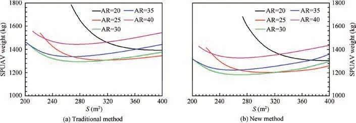
Fig 11 SPUAV weight of the two methods vary with aspect ratio and wingspan.
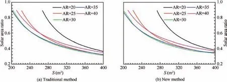
Fig 12 Solar area ratio of the two methods vary with aspect ratio and wingspan.
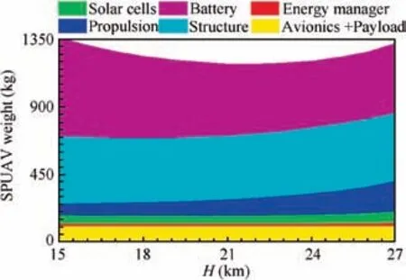
Fig 13 Subsystem weight varies with target altitude.
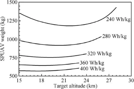
Fig 14 SPUAV weight varies with battery gravimetric energy density and target altitude.
The aircraft weight depends on the target altitude with various mission altitudes shown in Fig. 16. For different mission altitude, there is an optimal target altitude for minimum SPUAV weight. The optimal target altitude decreases with the decrease of mission altitude,as well as the SPUAV weight.The mission altitude reduces to 14 km, 13 km, 12 km, and 11 km, the optimal target altitude will be reduced about from 22 km to 19 km. Considering the mission altitude is reduced,the difference between the target altitude and mission altitude remains stable and the SPUAV weight will be reduced by 16.7% 28.8% 37.7% and 44.6% respectively.
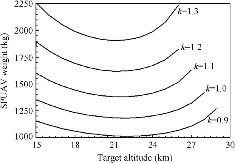
Fig 15 SPUAV weight vary with structural weight penalty coefficient and target altitude.
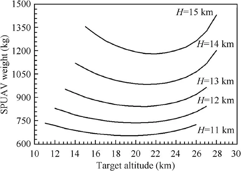
Fig 16 SPUAV weight varies with mission altitude and target altitude.
The effect of the design data on aircraft weight is shown in Fig. 17. The day numbers are 204, 234, 264 and 294, the corresponding dates are July 24, August 23, September 22 and October 22, the optimal target altitude is not sensitive to the date. The optimal SPUAV weight growth quickly, is 795 kg,933 kg, 1181 kg, and 1609 kg respectively.
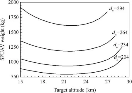
Fig 17 SPUAV weight vary with design date and target altitude.
5. Conclusion
The general optimization design method, considering propulsion system planning priority, of Solar-Powered Unmanned Aerial Vehicle (SPUAV)is reasonable and feasible. Compared with the traditional method, this general design method can effectively decrease the energy demand of night flights. Thus,significantly reduce the SPUAV weight.
The development of the energy density of the battery will weaken the application effect of the new method.
Under the different structural weight penalty coefficient,mission altitude, and design date, the new method has a great application effect, and it is not affected by these parameters.
Appendix A. Flight environment
Because of the special of SPUAV, the flight environment of SPUAV can be divided into two parts, one is the atmospheric environment, the other is the solar radiation environment.
The atmospheric environment includes air density, temperature, pressure, viscosity, and other parameters. The data required for the calculation are following the standard atmospheric regulations.
The solar radiation environment includes solar intensity,solar altitude angle and solar azimuth angle.
For a given latitude,date and height,the solar intensity at a given height SIhis given in Eq. (A1).
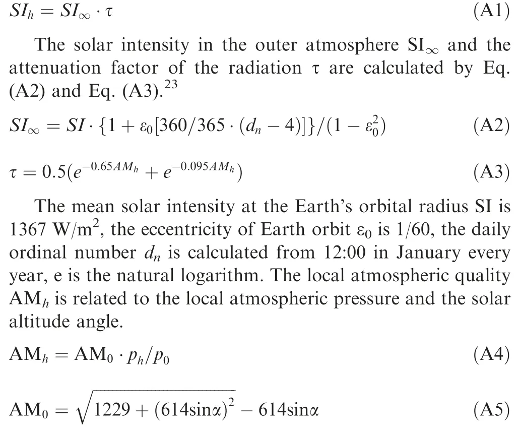
In the equations, phstands for the local atmospheric pressure, and p0stands for the pressure of sea level, the solar altitude angle α and atmospheric quality of sea level AM0are used.
Solar altitude angle α and azimuth angle β are calculated by Eq. (A6) and Eq. (A7).
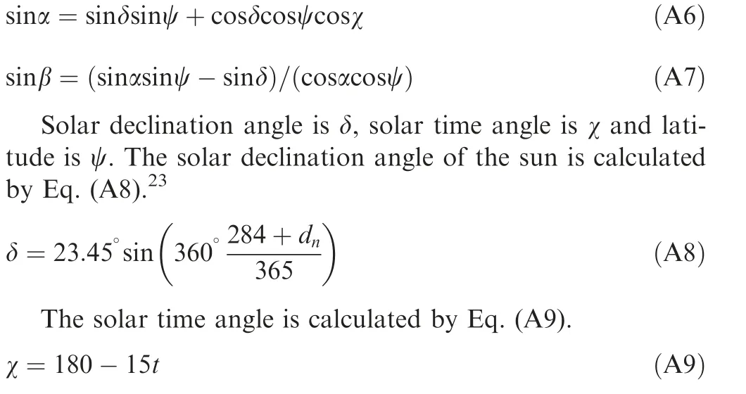
The real sun time is t, the time which the projection of the solar falls on the given latitude line is set to 12 o’clock.
According to the above equations, the solar intensity on May 17 (the daily ordinal number is 136) is calculated at 40 degrees north latitude as shown in Fig. A1. Fig. A2 displays solar radiation during a year.
Aerodynamics of aircraft
SPUAV usually uses a large aspect ratio aerodynamic layout.In the initial design stage, the lift-drag relationship is determined by the engineering estimation method as follows.24
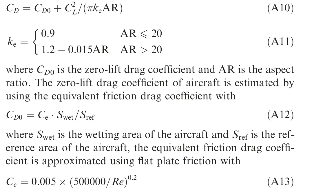
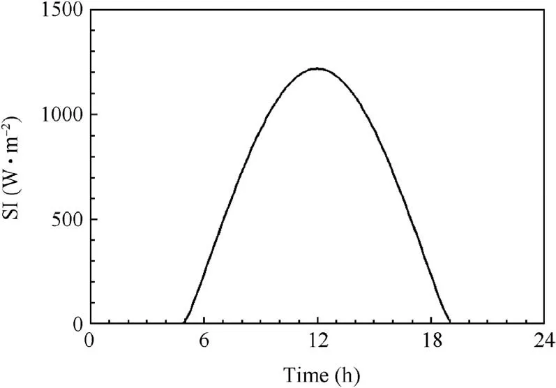
Fig A1 Solar radiation intensity during a day.

Fig A2 Solar radiation during a year at each latitude.
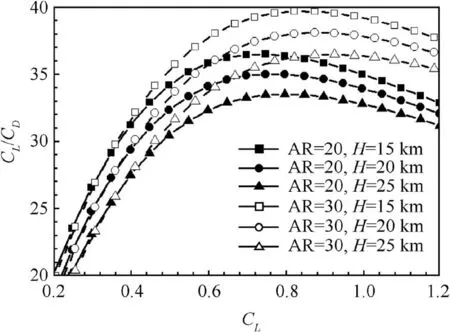
Fig A3 Change of lift-drag ratio to aspect ratio and cruising altitude.
The lift-drag ratio of different cruise altitudes and different aspect ratios calculated from the above formulas is shown in Fig. A3. Under the same aspect ratio, the higher the cruising altitude, the smaller the maximum lift-drag ratio. When the aircraft cruising altitude is the same,the larger the aspect ratio,the greater the maximum lift-drag ratio. This means that the above calculation method reflects the effect of cruising altitude, aspect ratio on aerodynamics lift and drag.
 CHINESE JOURNAL OF AERONAUTICS2020年8期
- CHINESE JOURNAL OF AERONAUTICS的其它文章
- Structural dynamic responses of a stripped solar sail subjected to solar radiation pressure
- Dynamic coefficients and stability analysis of a water-lubricated hydrostatic bearing by solving the uncoupled Reynolds equation
- Rotor airfoil aerodynamic design method and wind tunnel test verification
- A heuristic cabin-type component alignment method based on multi-source data fusion
- Effect of curing condition on bonding quality of scarf-repaired composite laminates
- Influence of uniaxial tensile pre-strain on forming limit curve by using biaxial tensile test
