Flow mechanism between purge flow and mainstream in different turbine rim seal configurations
Ziqing ZHANG, Yingjie ZHANG, Xu DONG, Xiao QU,Xingen LU, Yanfeng ZHANG,*
a Key Laboratory of Light-duty Gas-turbine, Institute of Engineering Thermophysics, Chinese Academy of Sciences, Beijing 100190, China
b School of Engineering Science, University of Chinese Academy of Sciences, Beijing 100049, China
KEYWORDS Kelvin-Helmholtz instability;Loss of fluid;Rim seal;Sealing efficiency;Turbine;Vortex flow
Abstract The rim seal is used to prevent mainstream ingestion to the gap between the vane of a turbine and its blade.In this article,the dolphin lip with a hook configuration and a large seal cavity with hook structures are designed based on the high-pressure turbine datum single shark lip rim seal configuration. The sealing effect and parameters of the flow field are measured by an experiment method and a numerical simulation is used to explain the mechanism. For three configurations,the effect of the leakage slot vortex on the efficiency of the seal and the influence of leakage vortex,generated by the interaction between purge flow and mainstream flow, are discussed in depth. The result shows that the reverse vortex formed by the dolphin lip rim seal with hook structure will increase the sealing efficiency.The seal configuration with a large cavity improves sealing efficiency to a greater extent than the datum structure. At different purge flow rates and with unequal seal structures, the purge flow produces three types of leakage vortices in the passage. Besides, the seal configuration with dolphin lip produces a Kelvin-Helmholtz instability at the interface of the purge and the mainstream flows at a low purge flow rate to induce new leakage vortex branches in the passage of the blade.
1. Introduction
Complex seal structures are designed and secondary air introduced from the compressor as cooling flows into the rim seal to prevent the ingestion of the mainstream.However,the leakage flow interacts with the secondary flow, and this results in an increase in secondary flow losses that have a significant negative impact on the aerodynamic performance of the turbine.Therefore, designing a suitable rim seal structure to balance the effects of sealing and impact on the mainstream has emerged as a popular subject of research in recent years.
Liao et al.1studied the rotor-stator disc cavity structure and found that the sealing effectiveness increased with the increasing purge flow rate.With regard to high purge flow rate,the distribution of sealing effectiveness was independent of the rotational Reynolds numbers. Liu et al.2compared the concentration-based sealing efficiency and temperature-based sealing efficiency. They found that these two efficiency were similar but different in distribution in the same condition as Le >1 (Le is the Lewis number, ratio of thermal diffusivity to mass transfer coefficient). The seal efficiency could be expressed by temperature-based sealing efficiency when the temperature of test seal flow was not much higher than the environment temperature. Wang et al.3found that the sealing effectiveness of radial seals was better than axial rim seals.Moreover, the minimum sealing mass flow increased with the increasing of rotational speeds. Cao et al.4studied the rotormounted protrusion structure effect on sealing performance and flow structure. They found that the increasing of the protrusion radial position and height could improve the sealing performance, and this effect increases with the increase of the rotational Reynolds number. Schuler et al.5found that axial overlapping compound geometry could effectively prevent mainstream ingestion and reduce the height of the boundary layer lifted by the purge flow, thereby reducing the coefficient of total pressure loss on the turbine blade. Savov et al.6compared the geometries of the single- and double-lip rim seals,and found that the latter required less flow to achieve the same sealing efficiency,whereas the former was sensitive to the overall Reynolds number. Erickson and Simon7proposed and compared the effects of‘‘shark nose”and‘‘dolphin nose”structures of the lip on aerodynamic and cooling efficiency.The results showed that the dolphin nose has higher cooling efficiency than the shark nose at different purge flow rates.Because the upper surface of the lip was far from the wall of the hub,a backflow vortex was formed near the sealing outlet,and sealing efficiency was high. However, owing to the rapid lifting of the cooling airflow, a relatively large loss in secondary flow loss occurred. Jia et al.8solved the temperature and deformation of the elastic body of the high pressure turbine disc in multi-physics field and found that the turbine rotor disc growth in radial resulting in ‘‘new” hot running rim seal clearance, which led to extra ingestion.
The interaction between purge and mainstream flows and the flow loss were also studied by some researchers in recent years. Song et al.9found that the purge flow could increase the horseshoe vortex intensity and cause separation vortex to enhance the local heat transfer coefficient of the endwall.McLean et al.10found that reducing the radial momentum of and the difference in circumferential momentum between purge flow and the mainstream could weaken the viscous shear layer near the hub, and could enhance the secondary vortex near the endwall through purge flow.Similar conclusions were drawn by Reid,11Hunter,12Gier,13and Schlienger14et al.Popovic´ and Hodson15,16found that the geometric characteristics of the rim seal influence overall flow loss. The seal structure with a large recirculation zone caused severe viscous dissipation that yields large flow losses. The dolphin nose structure formed a large recirculation zone at the outlet of the sealing structure, which increased sealing efficiency but caused greater flow losses.Jia and Liu17classified losses caused by the interaction between leakage and the mainstream into four categories that were not independent of one another,and found the shear-induced vortex and slot leakage vortex caused by purge flow.
Instability arises due to a difference in flow properties between purge flow and mainstream flow. In recent years,many scholars have conducted research on this subject. Chilla et al.18studied the unsteady interaction of seal leakage flow with the mainstream,and found flow interaction at the rim seal interface to be naturally unsteady such that it generated periodic vortex shedding into the rotor passage. Horwood et al.19claimed that instability in the outlet of the seal was caused by the tangential shear between the annulus and the egress flows,and was sensitive to the purge flow rate, whereas instability under large seal flow was completely suppressed.
The researchers also did some research on the heat transfer characteristics of the disk cavity after the mainstream ingestion for unequal seal structure.
It is clear from the above that past research focused only on properties of the flow passage in purge flow, and neither analyzed the vortex structure generated by it in the flow passage nor the specific direction of the purge flow in detail. In addition, research on instability only examined its occurrence,and did not go on to discuss how the vortex generated by the instability affects the flow structure in the flow passage.
In this paper, based on the datum seal Configuration A with the single-lip shark nose, and by reconsidering the seal cavity and the seal lip structure, two sealing structures are designed. Configuration B consists of using the dolphin nose lip shape and setting the hook on the lower surface of the lip. Configuration C uses the shark nose structure, but the hooks are arranged above and below the cavity to increase the area of the seal cavity.Through experiments and numerical simulations of these three configurations, the flow structures with the sealing effect and the vortex structure generated by the purge flow in flow passages are investigated. The influence of these factors on the sealing efficiency, flow loss, and blade loading is calculated and clarified. Moreover, mechanisms of the Kelvin-Helmholtz instability produced under certain operating conditions are discussed. These laws provide a better understanding of the general flow of the sealing structure.
2. Experimental and numerical methods
2.1. High-speed linear cascade test bench and sealing structure
A high-speed linear cascade test bench was used in the experiment,as shown in Fig.1,and contained an air source,settling chamber, contraction, straight section, and a test section. The test section could set a rim seal configuration and a secondary air supply chamber configuration by replacing a turntable at the root of the blade.The mainstream air supply was provided for two centrifugal air compressors with a rated power of 1000 kW. The maximum supply pressure was 1 MPa and the maximum supply flow was 5 kg/s. The sealing air supply was provided by a screw compressor with a rated power of 100 kW. The air supply pressure was 1.2 MPa, and the maximum air supply flow rate was 0.25 kg/s.The flow rate of purge flow entering the sealing structure was controlled by adjusting the difference in flow between the inlet and the outlet of the secondary air supply chamber. Through measurements and adjustments before the test, the uniformity of air at the inlet and its periodicity at the outlet were made to satisfy the relevant requirements.The Mach number of the turbine’s cascade outlet could be adjusted by adjusting the flow rate of the centrifugal air compressor and inlet passage area. The inlet angle of the cascade could be adjusted by rotating the turntable of the fixed cascade.
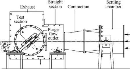
Fig. 1 High-speed linear cascade test bench.
The measuring devices used a Pitot tube, three-hole probe,static pressure hole, and precision mass flowmeter to measure the parameters. The pressure signal was converted by using Digital Sensor Array (DSA) before collecting data. The total pressure was measured at the inlets of the test section and the sealing configuration, and the pressure and distribution of mid-span velocity of the blade passage were measured at 0.4Cx(Cxis the axial chord) behind the cascade. The static pressure hole was set on the surface of the blade.The load distribution of the blade was measured and the mass flowmeter was used to measure the mass flow of the sealing stream.
The experiment used a high-pressure turbine rotor cascade.Four linear blades, suction, and pressure surface at the two ends formed five flow passages. The measurement was executed within a 1.2 times pitch. The experiment used the designed outlet Mach number and designed incidence. The parameters of the cascade are listed in Table 1.
The object of this research is the rim seal structure in front of the turbine blade cascade. Fig. 2 shows the three-rim seal structure used in this study.Seal A is the datum configuration consisting of a seal cavity and a shark nose seal lip.For Seal B,the seal cavity remains constant and the lip is changed to adolphin nose with a hook structure at the lower surface. Its minimum clearance is located under the seal cavity.The upper surface of the lip of the dolphin nose is far from the surface of the hub.Seal C is identical to the seal lip of datum,its seal cavity area is enlarged, and hook structures are arranged at the upper and lower surface exits of the cavity. The seal clearance of the three seal configurations are 0.8 mm.The structural and test flow parameters of seal are listed in Table 2.
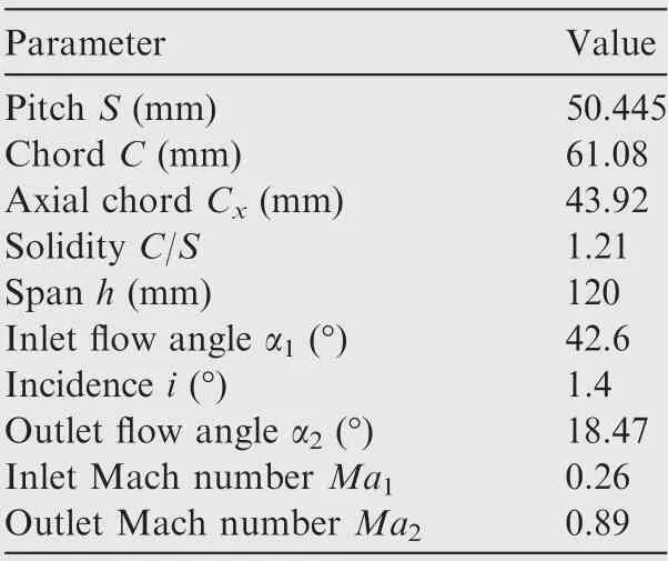
Table 1 Parameters of high-pressure turbine rotor cascade.
The main purpose of Seal B is to investigate the effect of the dolphin nose of upper part of the seal structure on the loss of secondary flow,and to investigate the effect of the hook structure of lower part of the seal structure on the sealing efficiency.The main purpose of Seal C is to investigate the effect of the area of the seal cavity on sealing efficiency and the loss of secondary flow. However, in order to ensure that the size of the channel from the disk chamber into the cavity of the lower part of the seal structure,and the clearance from the cavity into the mainstream of the upper part of the seal structure are the same as Seal A, the hook structures is set.
2.2. Numerical methods
In the CFD calculation, to save computing resources, the calculation of the height of the mid-span is used to completely capture the endwall and mainstream flows because the endwall flow is concentrated in the blade root position.Gambit is used to generate the mesh for the fluid domain and the seal domain,which is shown in Fig. 3. The domain of calculation is the entire connected region.The mesh nodes are all matched without interruption. There is no interface in the middle, and the surface of the periodic boundary is a periodic matching mesh to ensure the accuracy of the calculation and continuity of the streamline during post-processing. According to the verification of mesh independence, the entire domain computation is divided into 5.38 million cells.The distance between the wall and the first layer is 1×10⁻⁶m and the maximum y+value is under 1, which meet the precision requirements of the turbulence model.
CFX is used as solver for the numerical simulation because it has high precision,and is extensively used in turbomachinery calculations in many in-house and commercial fluid-solving codes. CFX uses the finite volume method based on the finite element method.It adopts an implicit coupling pressure-based method which is the use of a coupled formulation for the mass and momentum equations20. In this study, the RANS(Reynolds-Averaged Navier-Stokes) method is used. A comparison with the experimental results show that the Reynolds stress term using the k-ω turbulence model to close the Navier-Stokes equations yielded flow field results more consistent with the experiment.
The mainstream boundary conditions for the numerical simulation are set for the total pressure, total temperature,and airflow angle. The total pressure is set using the total distribution of radial pressure measured by the boundary layer probe to account for the inlet boundary layer. The outlet is set to the static pressure boundary condition, and the surface of the wall uses the adiabatic and non-slip boundary conditions. The boundary conditions of the sealing inlet are set for speed in the circumferential direction, which is opposite to that of the mainstream, to simulate the circumferential movement of purge flow in the rotating disk cavity.The radial direction is also set to a certain speed to determine the purge flow rate.

Fig. 2 Schematic diagram of three-rim seal configurations.

Table 2 Structural and flow-related parameters of highpressure turbine seal configuration.
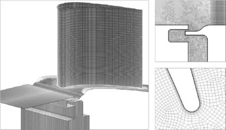
Fig. 3 Computational mesh in fluid domain.
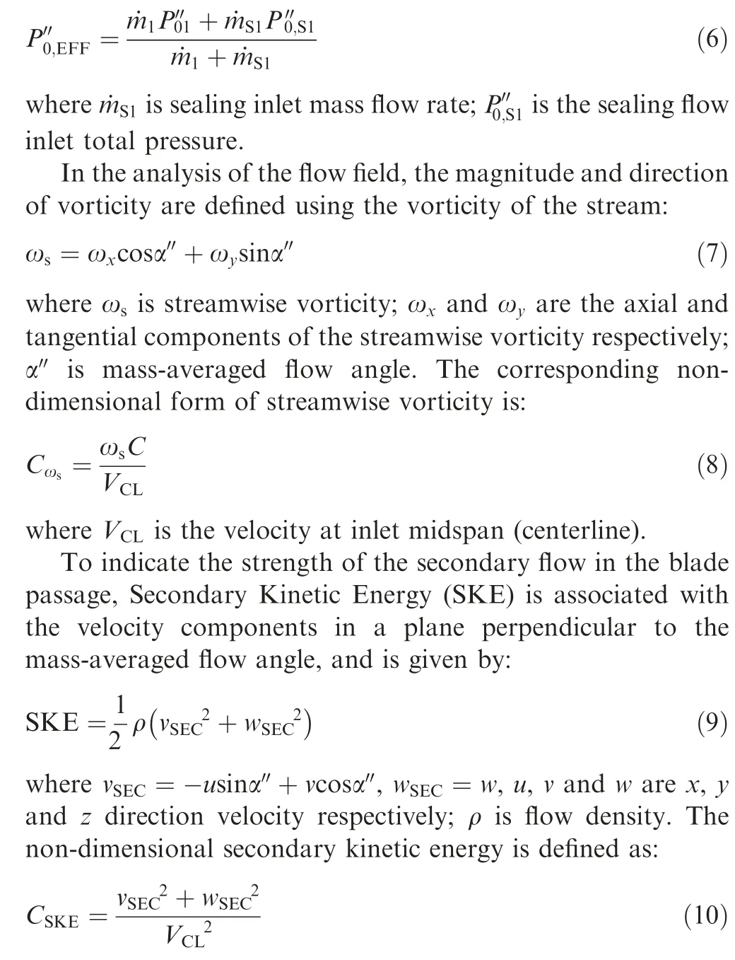
Fig. 4 shows the comparison between the results of the numerical simulation and the experiment (EXP)Cp0and deviation at 1.4Cx. Cp0is the flow total pressure coefficient:

where P0′1′is mainstream inlet mass-averaged total pressure; P2′′is outlet mass-averaged static pressure; P0is local total pressure.Deviation is the difference between the local circumferential average outlet airflow angle α2and the blade cascade outlet airflow angle at midspan α2,profile.It is clear that the numerical results are consistent with the experiment in terms of the total pressure coefficient contour. The shape and height of the passage vortex are consistent, and the deviation angle matches well.The experiment results basically captured the mainstream overturn and underturn caused by the secondary flow.Although the flow deviation caused by passage vortex at the 0.05 span position has slight difference between the experiment and simulation values.This is because the numerical results are simulated using full turbulence, and in the experiment, part of the fluid in the inlet section of the blade is in the laminar boundary layer state. Therefore, the state of the inlet section boundary layer affects the shape and strength of the passage vortex. However, the numerical results are relatively reliable,and can be used for further mechanistic exploration.
2.3. Related variables and data reduction
One of the purposes of this research is to investigate the effects of different purge flow rates on the fluid domain. The purge flow rate is defined by leakage fraction:

where ˙mSand ˙m1are the mass flow rates of the sealing and the mainstream flows,respectively; ˙minand ˙moutare the mass flow rates of the inflow and outflow of the secondary air supply chamber that can be measured by the mass flowmeter. Mainstream flow in the experiment is calculated according to the following formula:

where KWis the flow coefficient (0.994-0.998); A is the flow measurement cross-sectional area; P01is inlet total pressure;T01is inlet total temperature; P1is inlet static pressure;R=287.06 J/(kg·K)is air gas constant;γ=1.4 is specific heat ratio of air.
The sealing effect of the sealing structure under different working conditions is indicated by the sealing effectiveness:
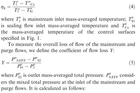

Fig. 4 Comparison of results of numerical simulation and experimental results at 1.4Cx.
3. Results and discussion
3.1. Analysis of blade loading
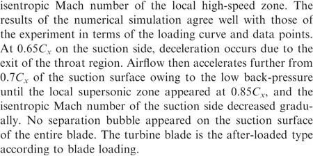
Blade loading at the mid-span of the high-pressure turbine cascade without a seal structure is shown in Fig. 5. The vertical axis is static pressure coefficient:

3.2. Sealing principle and characteristics of purge flow
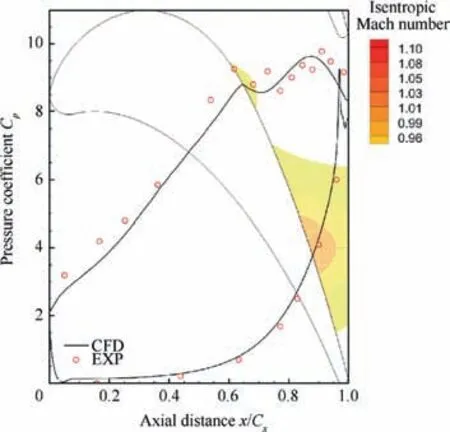
Fig. 5 Blade loading without seal structure.
The results of the experiment and numerical simulation show that the sealing effectiveness of the three seal structures is high,and the ingestion of the mainstream is prevented under a small purge flow. To clarify the interaction between the fluids in the same circumferential position when the mainstream ingested,and to explain the vortex structure used to prevent mainstream ingestion, a small purge flow (LF=0.1%) is chosen.The circumferential distribution of the mainstream ingestion and sealing leakage can be considered according to the circumferential distribution of the radial velocity w of the horizontal plane of the seal slot outlet, as shown in the flood contour of Fig. 6. Negative velocity w represents ingestion and positive velocity represents leakage.In addition,for a clear presentation, three pitch sections are selected: the main ingestion side near the pressure side of the blade(Plane 1),the same trend of ingestion and leakage mid-pitch (Plane 2), and when the leakage is maximum (Plane 3). By drawing the streamline on the three sections, the non-dimensional temperature θ is represented as colors, the θ is calculated as follows:

where T is local temperature. The blue color represents the purge flow at lower temperature and red represents mainstream flow at higher temperature.
In order to obviously characterize, the plane vortex that produces the sealing effect in the seal slot or cavity is referred to as the leakage slot vortex. The three-dimensional (3D) vortex in the blade passage induced by the leakage slot vortex,or for other reasons when purge flow leaks to the mainstream, is referred to as the leakage vortex in later.
The principles of preventing mainstream ingestion for the three seal configurations are distinct, and the effectiveness of sealing is different among them as shown in Fig. 6. The effectiveness of sealing is strictly related to the flow form in the seal structure, such as fluid type, position and size of the leakage slot vortex, and other small vortex structures. They are determined by the geometry of the seal structure and leakage fraction. The effectiveness of sealing and flow loss of the three configurations at LF=0.1% are shown through solid lines in Fig. 7.
For Seal A, the mainstream passed through the minimum clearance and ingested the sealed cavity,forming a leakage slot vortex in the cavity with purge flow on Plane 1. In this position, the purge flow prevents further ingestion of the mainstream. However, the leakage slot vortex is close to the control surface of the disk chamber,and the mainstream mixes with the purge flow to reduce the effectiveness of sealing.Purge flow has little influence on the mainstream because the leakage slot vortex is located far from the mainstream in the cavity so that flow loss is the lowest.
For Seal B, the mainstream is largely ingested into the seal cavity to form a leakage slot vortex in it. A hook structure is set on the lower surface of lip to form a reverse vortex after purge flow out of the hook, contrary to the direction of the leakage slot vortex. This effectively prevents the mainstream from being ingested into the disk chamber, because of which the sealing effectiveness of Seal B is high. But leakage on the suction side is relatively high because of the dolphin nose.Thus, the loss in Seal B is slightly higher than datum.
For Seal C,the mainstream easily flows circumferentially in the cavity owing to the large seal cavity, and it is difficult to continue radial ingestion into the disk chamber. The leakage slot vortex is formed in the cavity by the mainstream and purge flows. In addition, the hook structure on the lower surface of the seal cavity effectively prevents ingestion into the disk chamber.The effectiveness of sealing is relatively high for these reasons, but the large seal cavity produces higher viscous dissipation of the purge flow, which results in larger flow loss.
Furthermore,the effectiveness of sealing at a slightly larger purge flow rate is analyzed.Fig.8 shows the distribution of the mainstream ingestion and purge flow leakage at LF=0.1%and 0.5%on Plane 1.Plane 1 is chosen for the analysis of sealing efficiency because the large radial pressure gradient in the endwall region and ingestion is most significant as shown in Fig. 6. At a purge flow rate of LF=0.5%, the flow structure in the seal cavity is significantly reformed compared with that at LF=0.1%.The sealing effectiveness of the three configurations significantly improves, and purge flow is entirely developed, and enters the mainstream. For the three seal configurations, a leakage slot vortex mainly composed of the purge flow is formed in the seal cavity. But because the new purge flow structure has just become stable at this purge flow rate, the difference of sealing effectiveness between the three seal configurations is slight, and all are at approximately 0.94 (black hollow square data points in Fig. 7). This is because the effectiveness of Seal B is inherently high, and that of Seals A and C significantly improves due to full leakage of the purge flow. Moreover, the areas of the leakage flow paths of Seals A and C are nearly identical, as shown in the circular area in Figs. 8(d) and (f).
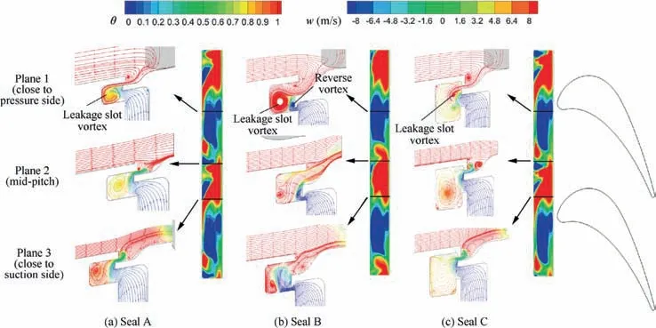
Fig. 6 Mainstream ingestion and sealing vortex at LF=0.1%.
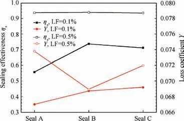
Fig. 7 Sealing effectiveness and flow loss coefficient of three configurations at LF=0.1% and 0.5%.
The temperature distribution of the intermediate height of the inner surface of the seal cavity is presented in Fig. 9. It is clear that the order of temperatures of the seal configurations is Seal B >Seal A >Seal C. A large part of the mainstream ingests into the seal cavity because the dolphin structure causes the temperature of the cavity in Seal B to be the highest. The temperature of the cavity in Seal C is the lowest because the lower surface of the lip is far from the upper surface of the lower hook of the cavity.Moreover,the large area of the cavity causes a greater inflow of the purge flow to cool it down.Therefore, from the perspective of preventing hightemperature mainstream from entering the seal cavity,the Seal C delivers the best effect.
3.3. Interaction between purge flow and mainstream
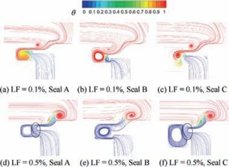
Fig. 8 Sealing vortex at LF=0.1% and 0.5% in Plane 1 of three configurations.
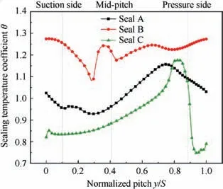
Fig.9 Temperature distribution at inner surface of seal cavity at LF=0.1%.
The vortex system of the blade passage is different from the unsealed structure primarily due to the formation of the leakage vortex in it.The purge flow out of the seal slot forms three types of leakage vortices as shown in Fig. 10. The first type is the suction side leg of the leakage vortex formed close to the suction side of the blade, and is the most prominent variation in the vortex from the conventional unsealed flow passage.Purge flow out of the seal slot at the blade leading edge hits the recirculation zone of the horseshoe vortex to form a counter-rotation,and develops the suction side leg of the leakage vortex.The second type of vortex is the pressure side leg of the horseshoe vortex formed by the purge flow at the pressure suction of the blade leading edge at high purge flow rates. In this situation,the pressure side leg of the horseshoe vortex consists of the boundary layer of the mainstream and partial leakage flow. This is different from the horseshoe vortex only formed by the mainstream boundary layer when the structure is unsealed.The third type is the leakage vortex formed by the purge flow at mid-pitch.In this position,the trend of ingestion of the mainstream is identical to that of the purge flow leakage,and is induced by the shear force between the mainstream and purge flow.Fig.11 shows the typical flow structure in the blade passage using the seal structure. Therefore, the main component of the passage vortex is the joint action of the leakage vortex and the pressure side leg of the horseshoe vortex.
The purge flow forms unique vortex structures after entering the mainstream, where these structures are related to the purge flow rate.Fig.12 shows the 3D flow streamline of purge flow at different purge flow rates. Red represents positive streamwise vorticity values and blue represents negative values.
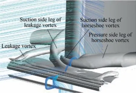
Fig. 10 Vortex structures at exit of rim and leading edge of blade.
At a small purge flow rate of LF=0.1%, the purge flow flows out from only the suction side, and is far from the suction side of the blade. This distance is the longest in Seal B because the purge flow close to the suction side flows out directly, and that close to the pressure side is driven by the mainstream of the ingestion to the suction side leg of the leakage vortex of the suction side of the next blade. This is indicated by the arrow in the diagram for Seal B when the purge flow is minor.In this case,it keeps away from the suction surface of the blade because the mainstream enters the seal slot largely due to the dolphin nose and drove purge flow away.In this situation, the purge flow forms only the leakage vortex by the shear force in the mid-pitch seal slot and intersects the pressure side leg of the horseshoe vortex in the blade’s passage.The suction side leg and pressure side leg of the leakage vortex not form.
At a larger purge flow rate of LF=0.5%, the purge flows of Seals A and C flows out from nearly the entire circumference and forms three distinct leakage vortices, as indicated in Figs. 12(d) and (f). For Seal B, the purge flow still only flows out near the suction side, but is different from that at LF=0.1%, the vortex is the suction side leg of the leakage vortex and the vortex formed by the Kelvin-Helmholtz instability, which will be explained in the next paragraph.
Note that as the purge flow rate increases to 0.5%, the degree of leakage of purge flow is close to the mainstream ingestion, and the Kelvin-Helmholtz instability occurs on the suction side of the surface of the seal outlet in Seal B as shown in Fig. 13. Fig. 13(a) shows the static pressure distribution on the pitch plane where instability occurs at the rim. Pminis the lowest pressure in this pitch plane. The figure indicates that high- and low-pressure regions appears in turn in the circumferential direction. The low-pressure region in the shear layer produced by the mainstream and the purge flow indicates Kelvin-Helmholtz vortices in this region, which is consistent with previous research.21Fig. 13(b) shows the pressure distribution on the straight line across the core of the vortices shown in Fig. 13(a). It also shows that in the region where instability occurs, pressure changes sharply and fluctuates, which also verifies the occurrence of the Kelvin-Helmholtz instability.Fig. 13(c) shows the contour of the circumferential velocity distribution of the pitch plane and radial velocity on the horizon plane of the outlet of the rim outlet in the unstable region.Because the mainstream and seal flow has opposite circumferential speeds, according to the interface of the two speeds, the Kelvin-Helmholtz instability causes significant blending between the mainstream and the purge flow to form multiple vortices at shorter circumferential distances.
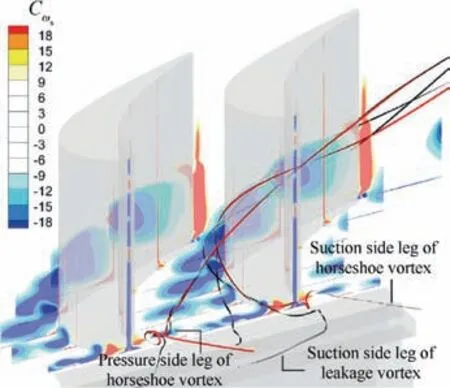
Fig. 11 Streamline and stream vorticity in blade passage using Seal A.
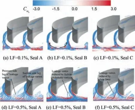
Fig. 12 Streamline of purge flow at variable rates for three seal configurations.
Fig. 13(d) shows the vortex structure near the endwall in the fluid domain according to the Q-criterion. The value of the criterion is 4.963×10⁷. The Kelvin-Helmholtz vortices generated on the pitch plane forms three new leakage vortices on the suction side through a mixture of purge flow out of the seal slot and low-energy boundary layer fluids of the mainstream,different from the suction side leg of the leakage vortex as shown in the black box section in Fig.13(d).From the color of non-dimensional streamwise vorticity, it is clear that the direction of rotation of the new leakage vortex is identical to that of the suction side leg of the leakage vortex, and merges into it after some remoteness. The Kelvin-Helmholtz instability reduces overall flow loss at this purge flow rate as shown in Fig. 7 because the circumferential speed of purge flow is opposite to that of the mainstream, and the circumferential speed of the partial mainstream in the Kelvin-Helmholtz vortices decreasing weaken the intensity of secondary flow.
Besides, since Kelvin-Helmholtz instability is an unsteady phenomenon, unsteady calculation and analysis of this case are performed to show this phenomenon more clearly. The timestep is set as 1×10⁻⁴s, and the total time is set as 0.65 s for unsteady calculation. We focus on the region of the black box locates in Fig. 13(a), and the flow field changes with time of the region is shown in Fig.14.t is time and T represents the time period of a vortex generation. The Vmainstreamand Vpurgefloware circumferential speed of mainstream and purge flow respectively which are opposite direction. Take the generation and development of a vortex as an example:Vortex A is generated at 0.66 normalized width by the instability caused by the parallel shearing motion of mainstream and purge flow.As time goes by,the vortex becomes larger and the position migrates with the direction of the mainstream circumferential velocity, as indicated by the black dotted arrow.The vortex reaches the maximum size until t=1.667 T,then the vortex breaks away. During the development of Vortex A,new vortices will continue to emerge behind it,the black box enlarged view in t=1.667 T is the pattern of next one vortex.
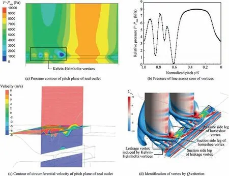
Fig. 13 Kelvin-Helmholtz vortices at outlet of seal slot.
2δ0represents the sum of the boundary layer thickness of the upper part of the fluid at the interface and the boundary layer thickness of the lower part of the fluid at the interface when the upper and lower fluids carry on the parallel shearing flow. The most unstable perturbation, known as Kelvin-Helmholtz mode can be predicted by the linear stability of a temporally evolving shear layer which uses the thickness of the shear layer 2δ022. In this mode, a longitudinal wavenumber α equal to

The distance between two adjacent Kelvin-Helmholtz vortex cores can be calculated though the above formula.According to the measurement, the boundary layer thickness 2δ0of this case is 0.56 mm. Therefore, the calculated distance between vortex cores is 3.82 mm which is approximate with the real distance (wavelength) values λx,r=3.7 mm as shown in Fig. 14.
Next, the direction of the purge flow is investigated separately. Lines of the purge flow are shown in Fig. 15 and Fig. 16, where the blue color represents negative streamwise vorticity and red represents positive streamwise vorticity.Most purge flow from different circumferential positions are anticlockwise, and are recognized by the Q-criterion with the mainstream as shown in the gray isosurface in Fig. 15. Then,with its development,the purge flow flows into the suction side of the blade through the suction side leg or pressure side leg of the leakage vortex. The purge flow is completely involved in the secondary vortex in the passage, and there is no part of it straight with the mainstream. It arises radially as the mainstream low-energy flow developed owing to the low energy of the purge flow.Divided into two parts at approximately 0.6Cx,one part still rotates in the anticlockwise direction with the leakage vortex into the passage vortex, and the other part flows into the wall vortex, the direction of rotation of which is opposite that of the passage vortex, then it merges with the trailing shed vortex downstream. In addition, a small part of the purge flow remains in the root of the blade as part of the corner vortex when the purge flow rate is large, as shown in Fig. 16.
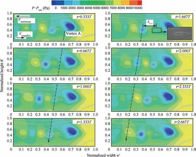
Fig. 14 Kelvin-Helmholtz vortices develop with time at instable region.
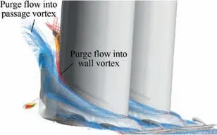
Fig. 15 Development of purge flow in blade passage.
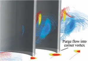
Fig. 16 Distribution of purge flow at trailing edge of blade.
The isoline of the coefficient of total pressure and contour of the coefficient of streamwise vorticity at 1.4Cxare shown in Fig.17.Three kinds of vortex structures formed in the trailing edge section. The blue region shows the passage vortex composed of the leakage vortex,pressure side leg of the horseshoe vortex, and partial small leakage vortex. The streamwise vorticity is negative, indicating that the vortex is rotated anticlockwise.The second vortex structure is the trailing shed vortex corresponding to the orange-yellow region on the upperright side of the figure, and its streamwise vorticity is positive,indicating that the vortex is clockwise. The third vortex structure is the corner vortex, represented by the red region at the bottom. Its streamwise vorticity is positive and large, indicating that vortex intensity is high.
The trend of intensity of the secondary vortex at a variable purge flow rate for three configurations is analyzed from the contour. Under a small purge flow rate of LF=0.1%, the intensity of the secondary vortex of Seal B is the highest, followed by Seals C and A. This corresponds with the loss coefficient Y of Seal B,which is relatively large as shown in Fig.7.This occurs because under a small purge flow rate,the dolphin structure of Seal B causes the radial velocity of purge flow in the mainstream to become large, and almost all purge flow is at a higher span position in the passage, as shown in Fig. 12(b). Thus, the intensity of secondary flow is enhanced.
At a higher purge flow rate of LF=0.5%, the intensity of the secondary vortex decreases slightly, and is the smallest for Seal B of the three configurations. The purge flow in Seal B flows out only on the suction side of the blade, and the mainstream low-energy boundary layer fluid is fully mixed with the purge flow under Kelvin-Helmholtz instability in the seal slot of the dolphin nose lip structure. The purge flow has high kinetic energy that decreases the circumferential speed of the partial mainstream,which is beneficial in weakening the intensity of secondary flow.
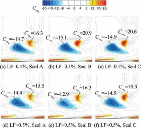
Fig.17 Contour of coefficient of streamwise vorticity and isoline of coefficient of total pressure at 1.4Cx.
As the purge flow rate increased, the overall flow loss increases even if the intensity of secondary flow declines,because in addition to the loss of secondary flow, mixing loss and flow loss in the seal structure occur, and rise up with the purge flow rate increasing.
The radial distribution of secondary kinetic energy for the structure without seal and the three seal configurations at LF=0.1% and 0.5% are shown in Figs. 18 and 19. It is evident that the purge flow increases the intensity of secondary flow in the front streamwise of the blade, such as at 0.2Cx.Downstream of the 40% axial chord of the trailing edge of the blade, the height of the passage vortex increases, and the intensity of secondary flow is less affected than that of the structure without seal, which is consistent with results of research by Schuepbach et al.23For different types of seal structures, the same results as for the vorticity contour are obtained from the secondary kinetic energy at LF=0.1%.The intensity of the passage vortex of Seal B is the highest;at LF=0.5%,the intensity of the passage vortex and the span height of Seal B is the lowest.The intensity of the corner vortex increases with the purge flow rate as shown in CSKEof the root of the blade in Figs. 18(c) and 19(c).
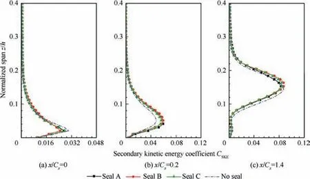
Fig. 18 Pitchwise mass-averaged coefficient of secondary kinetic energy at LF=0.1%.
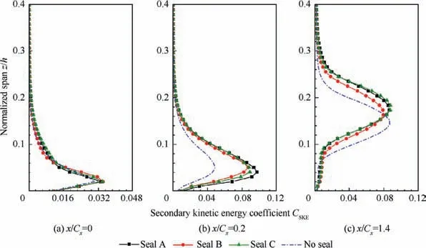
Fig. 19 Pitchwise mass-averaged coefficient of secondary kinetic energy at LF=0.5%.
Similarly, the deviation angle distribution at 1.4Cxat LF=0.1% and 0.5% are shown in Fig. 20. The law reveals by deviation is basically consistent with the law of the secondary kinetic energy.At LF=0.1%,the results of three configurations present little difference,but the deviation of Seal B is slightly high.At LF=0.5%,it is clear that the height of the passage vortex is the lowest,and its intensity and the height of Seals A and C are almost identical for numerical simulation and experiment results.
3.4. Influence of purge flow on blade loading
Forthe root loading distribution of the blade with seal structures shown in Figs.21(a)and 22(a),the purge flow reduces loading at the leading edge of the blade and increases loading at the trailing edge. For the mid-span load (40% of the full span) shown in Figs.21(b)and 22(b),the loading at the rear increases and the aft-loading characteristics of the blade are more prominent.The above effects are more obvious for higher purge flow rate.
The reason for the above is that the circumferential exit velocity of purge flow causes the mainstream to deviate from the design point to produce a negative incidence at the root of the blade,resulting in increasing pressure on the suction side of the blade’s leading edge. Pressure on the pressure surface changes slightly, and thus loading at the leading edge decreases.
Loading from the middle to the trailing edge of the blade increases because the suction side leg of the leakage vortex reduces pressure on the suction surface of the blade when it develops to an appropriate height, as shown in the circular area of Fig. 22(a).
At a higher purge flow rate,the purge flow and mainstream are more fully blended in the seal slot,and the intensity of the suction side leg of the leakage vortex is weak for the dolphin structure of Seal B in contrast with those of Seals A and C.Thus, the impact of purge flow on the load on the blade for Seal B is smaller than that on Seals A and C, as shown by the solid green line in Fig. 22(a).
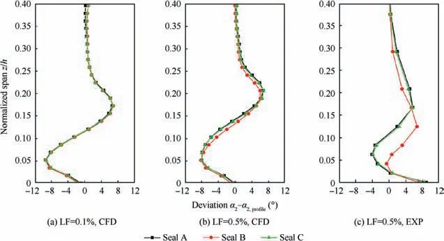
Fig. 20 Pitchwise-averaged yaw deviation angles at 1.4Cx.
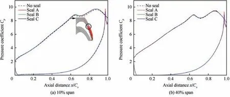
Fig. 21 Blade loading of three seal configurations at LF=0.1%.
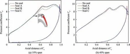
Fig. 22 Blade loading of three seal configurations at LF=0.5%.
4. Conclusions
In this article,the aerodynamic performance of three seal configurations is studied by experiment and numerical simulation.The effectiveness of the seal of three configurations is discussed, and the formation mechanisms of three types of leakage vortex and the effect of purge flow on secondary flow are investigated in detail.The main conclusions are as follows:
(1) The leakage slot vortex and reverse vortex generated by the hook of the lip’s lower surface are beneficial for improving the effectiveness of sealing; and increasing the area of the seal cavity can increase effectiveness by preventing the radial ingestion of the mainstream into the disk chamber. In general, the lower half of the seal structure affects the form of the leakage slot vortex as well as mainstream ingestion, which affect the effectiveness of sealing.
(2) For the interaction mechanism and loss of secondary flow, the most prominent characteristic in case of purge flow is the formation of the three types of leakage vortices, where the suction side leg of the leakage vortex is strong. The structure of the upper part of the seal is the key factor affecting the magnitude of the loss of secondary flow caused by purge flow.At higher purge flow rates, the dolphin lip had a small intensity of secondary flow due to the mixing of the mainstream and purge flow in the seal slot, whereas the intensity of the shark lip is slightly higher due to the leakage vortex.The purge flow merges into the corner vortex along the endwall so that the intensity of the corner vortex increases with the purge flow rate.
(3) The Kelvin-Helmholtz instability arises at lower purge flow rates for the dolphin lip configuration. This phenomenon occurs only when the upper face of the lip is far from the hub. New leakage vortex branches caused by the Kelvin-Helmholtz vortices are discovered. The presence of the Kelvin-Helmholtz instability strengthens the local mixing of the mainstream and purge flow, and reduces overall loss of flow by reducing the circumferential speed of the partial mainstream involved in the Kelvin-Helmholtz vortices.
(4) For loading the blade, the characteristics of aft-loading are more prominent due to purge flow. The configuration with dolphin lip is less affected than the shark lip at a small purge flow rate.
(5) It is necessary to consider the geometric structure for designing the seal structure. The rim seal could be divided into the upper part and the lower part by the rim seal lip. The more complex structure in the lower part helps to improve sealing efficiency which can produce complex forms of leakage vortex. For the upper part of the seal, increasing the distance between the upper end of the lip and the hub at a not very high purge flow rate can reduce the secondary flow loss to some extent because the mixing of the mainstream and purge flow will be enhanced. Moreover, at different flow conditions and altered blade types, the influence of purge flow on blade loading needs to be considered. The seal structure should be designed in light of practical considerations.
Acknowledgement
Financial support for the work presented is provided by the National Natural Science Foundation of China (Nos.51876202 and 51836008),whose support is greatly appreciated.
 CHINESE JOURNAL OF AERONAUTICS2020年8期
- CHINESE JOURNAL OF AERONAUTICS的其它文章
- Structural dynamic responses of a stripped solar sail subjected to solar radiation pressure
- Dynamic coefficients and stability analysis of a water-lubricated hydrostatic bearing by solving the uncoupled Reynolds equation
- Rotor airfoil aerodynamic design method and wind tunnel test verification
- A heuristic cabin-type component alignment method based on multi-source data fusion
- Effect of curing condition on bonding quality of scarf-repaired composite laminates
- Influence of uniaxial tensile pre-strain on forming limit curve by using biaxial tensile test
