Corrosion mechanism investigation of TiN/Ti coating and TC4 alloy for aircraft compressor application
Zhiping SUN, Guangyu HE, Qingjie MENG, Yuqin LI,Xiaodong TIAN
a School of Material Science and Engineering, Chang’an University, Xi’an 710064, China
b Engineering Research Center of Transportation Materials of Ministry of Education, Chang’an University, Xi’an 710061, China
c Science and Technology on Plasma Dynamics Laboratory, Air Force Engineering University, Xi’an 710038, China
KEYWORDS Coating defects;Hot corrosion;Microstructure;Salt spray corrosion;TiN/Ti coating
Abstract It is imperative to develop multifunctional erosion and corrosion resistant coatings for compressor blades of aircraft engines in harsh environment. PVD (Physical Vapor Deposition)technology has the advances in processing erosion-resistant coatings; however, the performance of PVD coatings to combat corrosion depends on various coating defects. Determining and comparing the corrosion performances of PVD TiN/Ti coating and uncoated TC4 alloy was the main objective of present work. The 960 h salt spray corrosion and 116 h hot corrosion tests were conducted to simulate the grounding and working environments of the aircraft compressors. The corrosion mechanisms due to the coating defects such as pinhole, columnar boundary and large grain were analyzed based on the OM,Confocal microscope,electrochemical measurements,SEM,XRD and EDS results. Owing to the disordered state associated with the columnar boundary and the coating defect,nitrogen could be easily replaced by oxygen in the hot corrosion process,these structures were channels for fast diffusion of oxygen. Moreover, the Gibbs energy changes of Ti oxidation and TiN oxidation were thermodynamically calculated according to the working condition of aircraft compressors, and considerable research effort was focused on mapping out the phase diagram of Ti, TiN and high pressure gases. The findings of this research can provide insights into developing multifunctional coatings for future aircraft engines.
1. Introduction
Sand erosion damage of aero-engine compressor blade is a key problem to reduce engine propulsion efficiency and increase maintenance cost.1-3Several nitride coatings have been applied to aircraft compressor blades for erosion mitigation with great success, such as ER-7 and Black Gold developed by MDSPRAD and GE for U.S.Army.TiN coating can extend the service life of compressor components up to 2-3 times.1,2,4However,air that contains water vapor or salt fog is ingested by the engines, often fouling compressors and initiating corrosion.4The corrosion changes the shape of the airfoil and the airfoil inlet angle, increases surface roughness and reduces the airfoil throat opening.Typically about 70-85%of gas turbine engine performance loss accumulated is attributable to compressor fouling and corrosion.5Therefore, work has continued to improve coatings in various applications.6-9On account of the coatings defects produced by PVD technique,the substrate may be exposed to the environment due to the pores and pinholes, leading to a poor corrosion resistance of nitride coatings.10The practical application of nitride coating depends not only on various mechanical properties, but also on the environmental adaptability, including corrosion resistance and oxidation resistance, as well as the service life under the complex coupling conditions such as erosion and corrosion.Nevertheless, the high-speed and high-pressure of aircraft compressor components are difficult to simulate under laboratory conditions, and few objective researches have been conducted so far. Although many characterizations of nitride coatings have been documented, most oxidation temperatures of nitride coating are above 500°C for cutting tools and antiwear die tools in the machining process,11,12which are beyond the service temperature of aircraft compressor, and there is inadequate literature studying these coatings with respect to the hot corrosion behaviors.
Herein, a comparative investigation was carried out on long-term salt spray corrosion behavior and 300°C hot corrosion damage of TiN/Ti coating, and TC4 was selected as the baseline material for comparison.The TiN/Ti coating had several advantages:the Ti intermediate layer interrupted the open structure of defects;the multilayered coating by introducing Ti layer had lower porosities than TiN single layered coating,which could provide better protection for corrosion. Besides,thermodynamic modeling was effective to overcome the experimental difficulty,so free Gibbs energy changes of Ti and TiN oxidation under high pressure were calculated, and considerable research effort was focused on mapping out the phase diagram of high pressure gas, TiN and various Ti oxides. These calculated and experimentally determined results as well as analysis of corrosion mechanism are valuable to guide the design of nitride coatings in the aviation industry.
2. Methodology
In this work,the TiN/Ti coating was prepared by multi-arc ion plating on the substrate of TC4 (Ti-5.60Al-3.07V, wt%), and constructed with soft Ti metal layer and hard TiN layer alternately,and two modulation periods were initially designed.To improve the quality and adhesion of coating,the argon plasma was used to clean the substrate surface with the flow of 80 cubic centimeter per minute and substrate bias of -500 V for 30 min. During the process of deposition, the substrate bias and arc current were kept at -200 V (direct current, DC)and 100 A, respectively. For the deposition of the TiN hard layer,nitrogen flow was set as 10 cubic centimeter per minute.In order to increase the deposition temperature, Ti sublayers were alternately deposited by sputtering in the TiN period.
Chloride ion is an important component of salt spray corrosion solution and hot corrosion solution.13,14Metals are prone to pitting in the medium containing chloride ions, and the blades tend to fracture from pitting under low stress conditions. In addition, Na2SO4is the most common salt in aero engine combustor environment, which is formed by the impurities in the fuel. Consequently, ensuring the environment adaptability of TC4 and TiN/Ti coating in the corrosive medium containing Cl,Na and S is an important link in the development of advanced engines. In the salt spray corrosion and hot corrosion experiments, the TC4 specimens with the size of 20 mm×10 mm×3 mm were prepared by conventional mechanical grinding and metallographic polishing,and the size of the coating specimens was 50 mm×20 mm×4.5 mm. Salt spray corrosion was conducted according to GJB150.11A-2009; the solution was 5%NaCl (weight percent); the test temperature was set at 35°C; fog deposition rate was 1-3 mL/(80 cm2·h); the procedure of 24 h spray and 24 h drying was alternately conducted and total test cycle was 960 h.The hot corrosion medium was 5%NaCl+95%Na2SO4(weight percent) solution, which was prepared and deposited on the surface of the specimen after atomization. The deposition rate was 0.51 g/m2. Totally 116 h hot corrosion of 29 cycles was carried out at 300°C.To reveal the effects of higher temperature, the 500°C/4 h hot corrosion for TC4 was also conducted. To draw the hot corrosion dynamic curve of TC4 alloy and TiN/Ti coating, 10-4precision balance was used to weigh the specimens every 4 h corrosion test.Before weighing,the deposition salt was washed away. The microstructure of each specimen was observed using optical microscopy (Olympus BX61),Confocal microscope and scanning electron microscope (TESCAN or MCRI). For the SEM observation, when the beam of electrons hit the sample,secondary electrons were released from the sample to provide an image. The secondary electron detector was commonly used to analyze the coating surface, corroded coating surface and corroded TC4 surface.The backscattered electron detector was commonly used to analyze the sectional microstructure of the coating, corroded coating and corroded TC4 substrate.The number of backscattered electrons reaching a BSE detector was proportional to the mean atomic number of the sample, it was very helpful for quickly distinguishing different phases of the polished sectional samples. SEM equipped with X-max energy dispersive spectroscopy was used to detect the compositions.Phase identifications were conducted by Bruker D8 X-ray diffraction with a Cu Kα source (wave length: 0.15418 nm). Potentiodynamic polarization tests were conducted in 5%NaCl (weight percent) solution using VersaSTAT 3F equipped with three electrode cell, including Pt counter electrode and a SCE reference electrode. The polarization curves of the TiN/Ti coating and TC4 substrate were generated from the exposed area of 1 cm2at a speed of 1 mV/s. The working electrode was stabilized till the fluctuation of open circuit potential was less than 50 μV in 300 s. The corrosion current Icorrand the corrosion potential value Ecorrwere determined by the Tafel extrapolation. Electrochemical impedance spectroscopy (EIS) analysis of freshly polished TC4 alloy and TC4 alloy after 960 h salt spray corrosion were carried out with a frequency range from 10 mHz to 100 kHz at 10 mV amplitude voltage.
The Gibbs energy change ΔG of a chemical reaction was the difference between the products of the reaction and the reactants. If the Gibbs energy of the products was less than that of the reactants,there would be a driving force for the reaction to occur.Generally,hot corrosion occurred on the basis of oxidation.In the initial stage of hot corrosion,the effect of deposition corrosive medium was not obvious; it was principally oxidation process, so Gibbs energy change of oxidation was calculated in this work.For the oxidation of metal,the equilibrium partial pressure PO2could be read from Ellingham graph,and by comparison with environmental partial pressure, the possibility of oxidation could be determined. If the environmental partial pressure P′O2was higher than the equilibrium partial pressurePO2, it would promote oxidation reaction.The difference energy ΔG could be calculated on the basis of Vant Hoff formula to reflect the effects of environmental pressure and temperature. Ti was the main constituent of TC4, so the ΔG of the oxidation reaction of Ti was calculated in the temperature range of 300-500°C and in the pressure range of 1-30 atoms according to the working condition of aviation compressor. Equally, the ΔG of TiN oxidation reaction was calculated in the same condition. Besides, the phase diagram of the Ti-N-O ternary system was calculated based on the extrapolated thermodynamic description of Ti-N binary and Ti-O binary by commercial software Pandat.
3. Results and discussion
3.1. Thermodynamic calculation
According to Vant Hoff formula Eq. (1), PO2was equilibrium partial pressure, and the decomposition pressure of oxide,which could be obtained from Ellingham diagram at each temperature. P′O2was the actual oxygen partial pressure. Oxygen accounted for 21% of the total atmospheric pressure.

According to the assessed Ti-O phase diagram, the stable condensed phase richest in O was TiO2.15Stated thus, PO2was obtained from the Ellingham Diagram of the reaction Ti+O2→TiO2.16was the actual oxygen partial pressure.According to Eq. (1), temperature and P′O2jointly affected the value of ΔG. The input variables were concerned in the range of 300-500°C and 1-30 atmos.
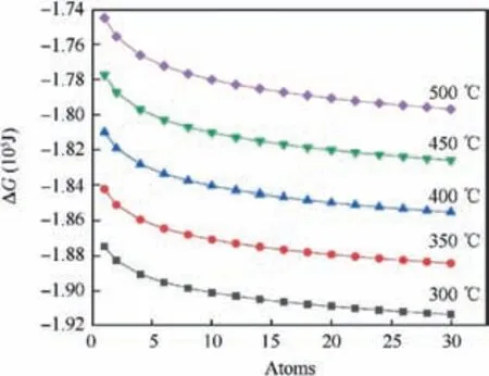
Fig. 1 Gibbs energy change of Ti+O2 →TiO2 reaction with the varying temperature and total atmospheric pressure.
Fig. 1 showed Gibbs energy change of Ti+O2→TiO2reaction with the varying temperature and total atmospheric pressure,the value of ΔG was more negative along the increase of actual oxygen partial pressure at each temperature; oxygen partial pressure affected ΔG at the magnitude of several thousand joule.In addition,high atmospheric pressure would raise the oxygen diffusion in the alloy and accelerate oxidation process. Moreover, ΔG was a monotone function of temperature,whose effect was opposite to that of actual pressure. Higher temperature led to less negative free energy change,but higher temperature could accelerate the inward diffusion of oxygen and outward diffusion of metal element in the view of dynamics.This had a decisive impact on the blade profile quality,and the challenge was further expanded for high temperature protective coatings.
For the typical TiN coating,the oxidation reaction in Eq.(2)was proposed by experimental determination. In the temperature range of 300-500°C,the stable standard state phases were TiN(s), TiO2(s), O2(g) and N2(g). The change in the standard state property of ΔG was calculated by a series of thermodynamic calculations based on Eqs. (3)-(5). The Gibbs function of pure element Ti, N and O were from the database released by SGTE(Scientific Group Thermodata Europe).17The Gibbs function of compound TiN and TiO2were from the modeling work by Computherm18and Yang et al.15respectively. When the temperature and the pressure were entered, and reaction determined the most stable phases in each condition. Fig. 2 showed the Gibbs energy change of the TiN oxidation with the varying temperature and total atmospheric pressure, the negative Gibbs energy change proved the direction of the oxidation reaction. Both of the effect of temperature and total atmospheric pressure had the same trend as Ti oxidation.Overall,higher oxygen partial pressure indicated only slight increase of Gibbs energy change for both Ti and TiN oxidation, which did not affect the driving force evidently. It was important to point out that large actual oxygen partial pressure would raise the oxygen partial pressure in the interface between TiN coating and the substrate, hence aggravating the oxidation and affecting the adhesive strength of the coating.


Fig. 2 Gibbs energy change of TiN oxidation with varying temperature and total atmospheric pressure.

In the process of erosion in harsh environment by ash,dust and sand particles, it was assumed that cracks initiated in the coating when local stress exceeded the tensile strength.Then the coating failure and exposion of the substrate gradually occurred, so TC4 substrate, TiN coating and Ti oxides coexisted in the erosion process. The phase boundaries of Ti,TiN and oxide phases depended significantly on the temperature and oxygen pressure, and were difficult to obtain by strictly limited experiments. On the other hand, time consuming trial-and-error experimentations could be supported by computer modeling. In this work, the thermodynamic description of Ti-N-O ternary system was obtained by the extrapolation of Ti-N binary and Ti-O binary.15,18Several sections of this system were calculated under different pressures. For the reference to the composition of atmospheric,the atomic ratio of N and O was fixed at 0.79:0.21, and the input pressure value was in the range of 1-30 atoms according to the working conditions of compressor. Fig. 3 showed the calculated section of the Ti-N-O ternary system by defining Y-axis point (5000°C, 10 atoms, x(N):0, x(O):0, x(Ti):1), Origin point (0°C, 10 atoms, x(N):0, x(O):0, x(Ti):1) and X-axis point (0°C, 10 atoms, x(N):0.79,x(O):0.21, x(Ti):0), the position of the calculated section was schematically illustrated and inserted in the left corner of this figure, and only Ti rich side from x(Ti):0.4 to x(Ti):1 was shown for clear demonstration. Typical single phase region, two phases region and three phases region were labeled. In the right side of this phase diagram, the main phases were the solid solution of Ti with the Bcc-structure and Hcp structure. In the left side of the phase diagram,there were mainly three phase equilibria of Gas+TiN+Ti2O3, Gas+TiN+Ti3O5, Gas+TiN+Ti4O7, Gas+TiN+Ti5O9, Gas+TiN+Ti6O11, Gas+TiN+Ti7O13, Gas+TiN+Ti9O17and Gas+TiN+Ti10O19,while only some of them were indicated in Fig. 3. These three phase equilibria illustrated TiN could coexist with multiple Ti oxide under high pressure. This changeover layer of Ti oxide could affect the adhesion and increase the stress between the coating and substrate. The TiN coatings were extruded by the oxidation product detached from the substrate, which made the corrosion and erosion of substrate more severe.
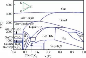
Fig.3 Calculated section of Ti-N-O system under pressure of 10 atmospheres.
3.2. Microstructure of TiN/Ti coating
Fig. 4 showed the microstructure of TiN/Ti coating, Fig. 4(a)and Fig. 4(b) were the surface and sectional microstructure of the coating respectively. Very few droplet defects were found due to the application of magnetic filtration, and these loosely adhered droplets were known to be localized initiation sites for corrosion. The composition of TiN surface layer was Ti-50.20N by EDS mapping determination. All alloy compositions in this paper were given in atomic percent (at%) unless stated otherwise. The thickness of coating and soft Ti layer was about 15.75 μm and 1.11 μm,respectively.The incorporation of both Ti layer and Ti sublayers enforced the diffusion in the interface, which inhibited the bonding mismatch of the interface and relived the residual stress by shear deformation.TiN of the coating was identified by XRD analysis in Fig.4(c).The depth of XRD diffraction was about 10 μm from the surface. This depended on absorption coefficient of the material to XRD,and was related to the intensity and frequency of incident XRD,so the soft Ti layer was also detected and identified as the Hcp structure in Fig.4(c).The structure and orientation of Ti should be affected by the coating processing parameters,such as the deposition temperature, the substrate bias and arc current.The alternate structures of TiN and Ti layer were also proved by the line scanning EDS analysis in Fig. 4(d). The maximum Ti content appeared in the Ti layer.
3.3. Salt spray corrosion
3.3.1. Salt spray corrosion behavior of TiN/Ti coating
TiN had excellent chemical stability and quite high corrosion potential (Ecorr) in aqueous NaCl solution. The protection of TiN coating in NaCl solution for substrate alloy was essentially mechanical barrier. But unavoidable defects (droplet,gaps,pinholes)were usually formed in the coating preparation process,19as pinholes were easily formed during columnar grain growth. The pinholes as well as columnar boundaries provided rapid path for corrosive medium to pass through;therefore, they were the initiation and location of pitting corrosion. When active chloride ions adsorbed on the defect of the coating, and the size of chloride ion was smaller than the size of coating defect, this enabled chloride ions to reach the substrate,and then the formation of soluble halides designated the nucleation of corrosive pitting.Fig.5 showed the morphology and mechanism of pitting corrosion of TiN/Ti coating,Fig.5(a)is the morphology of corrosive pitting after 576 h salt spray corrosion. The Tafel polarization plots in Fig. 5(b)showed that the corrosion potential Ecorrfor TiN/Ti coating shifted towards positive direction at -198.5 mV as compared to -497.8 mV for the TC4 substrate. The corrosion current Icorrwas found to be 310.0nA/cm2for the TC4 substrate and 114.4nA/cm2for the coating. Many researchers have also made the same discovery.20,21The corrosion potential difference promoted the corrosion cells between TiN and Ti, which were the cathode and anode for electrochemical corrosion,respectively. Accordingly, the anode reaction was listed in Eq. (6); the cathode reaction was listed in Eq. (7). From the above analysis,the schematic of multilayer TiN coating corrosion was drawn in Fig. 5(c). Corrosion current density depended on the corrosion potential difference and the area difference of TiN and Ti. Consequently, the corrosion resistance would decrease gradually over corrosion time, and this would increase corrosion density in the view of thermodynamics and dynamics.
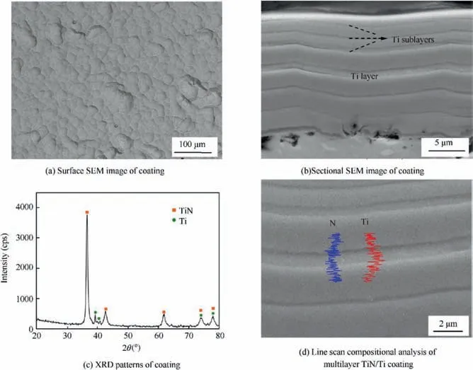
Fig. 4 Microstructure of TiN/Ti coating.
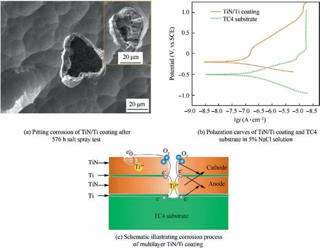
Fig. 5 Morphology and mechanism of pitting corrosion of TiN/Ti coating.

Along with the coating growth, fast merging clusters were observed, as in the insert image in Fig. 5(a). This region had different content of N from the region far from it. Both the compositional difference and electrochemical stability difference promoted local galvanic corrosion.The defect region with large grains would act as anode. The corresponding cathode reaction would occur in the defect-free coating. This mechanism was also demonstrated in Fig.5(c).Fig.6 showed another kind of corrosion, Fig. 6(a) was discovered after 336 h salt spray corrosion.Many cracks and small corrosion pits formed in this region,while little had changed for the most area of the coating after 336 h. Granular corrosion products were generated along the nearly square border.This caused the spallation of the coating and destruction of the coating integrity. Fig. 6(b) showed the corrosion evolution of this region after 960 h salt spray test. The substrate was exposed after the peeling of TiN coating. The EDS determined composition of this area was Ti-8.70Al-2.20V.The poor surface quality of the substrate might account for the possible cause of this kind of corrosion.Theoretically, TiN coating could protect TC4 substrate in NaCl solution, but the pinhole, gap, porosity, droplet and coarse columnar grain penetrating the whole coating would lead to corrosion. Chen el al.22proposed the synergetic effect of the packing factor and coating thickness on corrosion. A minimum value of [packing factor]×[TiN thickness] was required to safeguard against the corrosion in a certain environment. The packing factor was a normalized mass density,whereas the coating thickness related to the diffusion path of corrosive media. Matei et al.23estimated the crystalline size of nitride coating using Scherrer equation, it was summarized that small crystallite sizes would increase the number of defects in coatings. Those coating defects could be prevented by optimization of coating preparation parameters, application of emerging technologies and adjustment of the coating structure.Zhou et al.24used Electron beam-physical vapor deposition(EB-PVD) to deposit Ti/TiN coatings free of droplets, which were inherent to the unfiltered cathodic arc process. This was mainly because the diffusive arc with current density would eliminate the emission of spits and droplets. The structural design of multilayer coatings was also the alternative way to improve the quality of TiN/Ti coating,as the layered structure would suppress the growth of columnar defects, and thus prevent the movement of corrosive medium. JF Marco had proved the corrosion protection produced by the multilayered Ti/TiN/Ti/TiN structure was noticeably better than that of the single TiN coating.25Therefore, dense and multilayer coating was preferred in corrosive environment.
3.3.2. Salt spray corrosion behavior of TC4 substrate
Titanium had good corrosion resistance in many corrosive media, the standard electric potentials of 4s and 3d electron layers were small, which meant it was easy to lose electrons and form dense oxidation film with the thickness of several to dozens nanometers. The resistivity of natural passive state film of Ti alloy was in the magnitude of 108Ω·m.This ensured the good corrosion resistance of Ti alloy in atmosphere, water and other corrosive media. The formation of passive film was proved after 576 h salt spray corrosion by XRD; the related discussions have been published in another paper.26In order to further confirm the above findings,EIS measurements were performed to evaluate the corrosion mechanism by obtaining the Bode plots. It is well known that a greater arc radius of a Nyquist plot curve indicates a better corrosion resistance ability. Fig. 7 showed the morphology and mechanism of pitting corrosion of TC4 substrate, Fig. 7(a) described this trend with the TC4 alloy after 960 h salt spray corrosion having the higher arc radius than the freshly polished TC4 alloy. When the film-forming agents like OH-and O2were not adequate on the alloy surface, the formation of passivation film was unsustainable, so some pitting corrosions accompanied with this.Fig.7(b)was the overall observation of some pitting corrosions after 960 h and the image of one pitting corrosion obtained by Confocal microscope. The change of color represented the fluctuation of the sample surface, and the unit in this image was μm. Large yellow area was the base level of the sample, and convex region marked by white circle was the passivation film.The green region was the pitting corrosion caused by the rupture of passivation film,and the depth of pitting corrosion was assessed about 6 μm by color contrast. In Fig. 7(c), the alloy presented color contrast in some regions by OM observation. This demonstrated obvious passive film due to its different absorption and reflection characteristics of incident light. Moreover, the insert image in Fig. 7(c)showed more serious destroy of passive film and the evolution of corrosion.
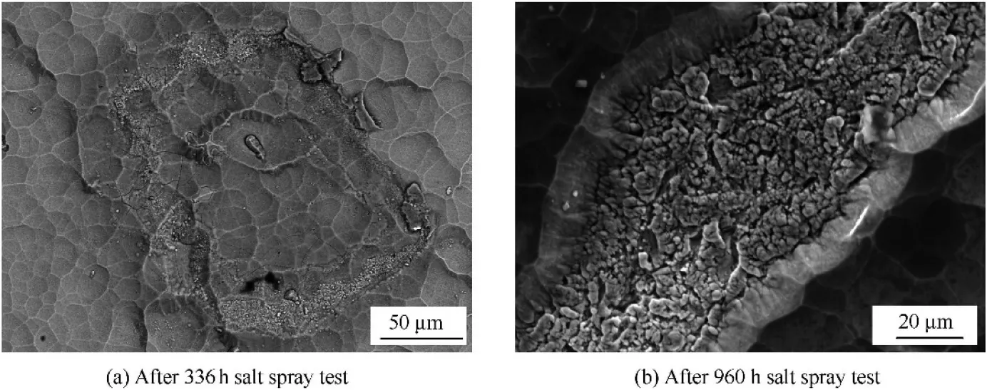
Fig. 6 Another kind of corrosion morphology of TiN/Ti coating.
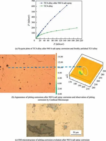
Fig 7 Morphology and mechanism of pitting corrosion of TC4 substrate.
3.4. Hot corrosion
3.4.1. Hot corrosion of TiN/Ti coating
Fig.8 demonstrated the weight change curve,the morphology of deposited salt and typical coating defects for the corroded TiN/Ti coating, the weight loss curves of TiN/Ti coating and TC4 substrate after 116 h hot corrosion were shown in Fig. 8(a). The weight loss of hot corrosion samples could be calculated by Eq. (8), where m0was the original weight of the test sample, miwas the weight of the sample after cleaning corrosive medium for each hot corrosion cycle,S was the deposition area of the test sample,and the negative value of ΔQ meant the weight loss due to spalling of oxidation and corrosion products.

There was no obvious weight change for TiN/Ti coating compared to TC4 substrate. It demonstrated that the coating could protect the substrate against corrosion to a certain extent.Fig.8(b) was the morphology of TiN/Ti coating after 4 h corrosion before the deposition corrosive medium was washed away. The composition of the deposition region was Ti-8.24N-14.23Na-5.33S-58.78O-0.40Cl,it is consistent with the macroscopic observed salt film on the surface of the coating.The existence of constitute elements Na, S, O and Cl in the deposition salt was proved.In addition,Ti and N in the coating were also detected. Fig. 8(c) and (d) were the corrosion microstructures for 88 h hot corrosion after the deposition salt was washed away. The pit with the size about 20 micron appeared. The composition at the bottom of pitting pit was Ti-0.77V-20.78O.No N element and high content of O element was detected.The substrate was exposed at the bottom of the corrosion pit, and the O element diffused into the substrate at high temperature.Fig. 8(d) showed one typical defects of the coating. In this region the coating was not compact and smooth. It provided a channel for the diffusion of O element in nitride,and the composition was determined as Ti-14.64N-42.67O.boundaries for fast oxygen diffusion. Ti, N and O occupied two crystallographically types of Wyckoff positions, i.e., 4a and 4b.The Ti atoms occupied the 4a position;N and O atoms were located at the 4b position.27TiNO was expected to have a chemical state intermediate between the oxide and nitride. In Shiyun Tang’s work, when the content of O was less than 40% in TiNO, the integrity of the CVD star-shaped TiN microstructure could maintain under the mild oxidation(below 500°C).28Diffusion of oxygen along the columnar grain boundary and the defects of the coating was the fastest step in the oxidization mechanism, the oxidation process would proceed with the stages involving nonstoichiometric TiON evolution, followed by a slow stage of TiO2formation.Sah had used XPS to investigate the chemistry of the oxide layer formed on TiN during the initial oxidation period, and proposed a model that the thin cap layer of TiO2grew slowly and changed from amorphous to crystalline.29The stratification along the columnar boundary of the TiN/Ti coating in Fig. 9(d) could prove the conjecture of TiO2formation. In addition to the above discussions, hot corrosion reactions of Ti layer in the multilayer coating would occur. According to Ref. 13, there was large distinction of mole volume between Ti and TiO2, the formation of oxides of the Ti layer resulted in the inevitable volume expansion, and the nitride layer adjacent to oxidized Ti was deformed and eventually led to cracks.This changeover of the coating during the hot corrosion process could affect the adhesion between the coating and substrate. The adhesion was compared for the TiN/Ti coating prior and post to hot corrosion. The adhesion of 72.5 N for the coating was significantly decreased to 20.1N for the corroded coating.Both the oxidation products and reaction products would lead to corrosions as shown in Fig. 9(e) and (f).
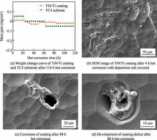
Fig. 8 Weight change curve, morphology of deposited salt and typical coating defects for corroded TiN/Ti coating.
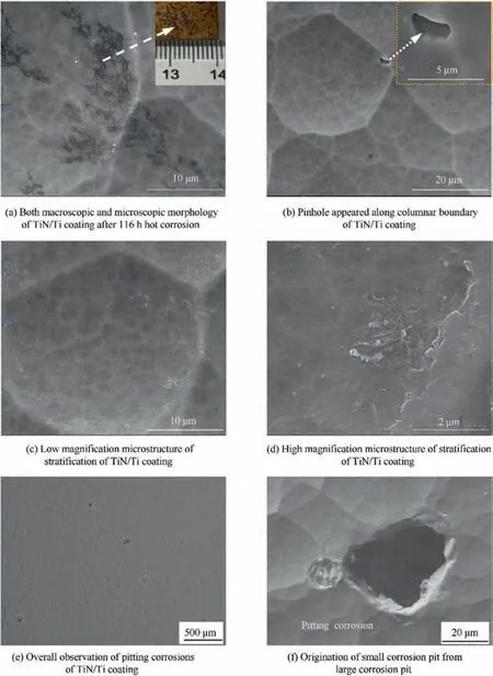
Fig. 9 Some macroscopic and microscopic characteristics of TiN/Ti coating after 116 h hot corrosion.
3.4.2. Hot corrosion of TC4 substrate
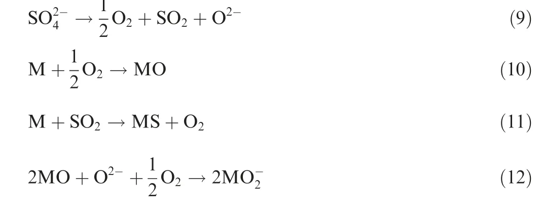
Fig. 10 showed the hot corrosion characteristics of TC4 substrate.In order to reveal the effects of temperature on hot corrosion,the hot corrosion at 500°C for 4 h was also conducted.The comparison between 300°C/4 h and 500°C/4 h corrosion was shown in Fig.10(a).Under the same magnification,higher temperature suffered more serious corrosion and rougher corrosive surface. Some corrosion pits with the size larger than 20 μm were formed under the deposition of corrosive medium.Though 500°C was lower than the NaCl+Na2SO4eutectic temperature of 626°C, pure mixture of NaCl and Na2SO4could not melt at 500°C in theory,but the deposition solution was difficult to absolutely dry before hot corrosion, and NaCl and Na2SO4could absorb certain moisture during the heating process of hot corrosion, so the solution of NaCl and Na2SO4was in existence. This accelerated the electrochemical reaction and chemical reaction in the hot corrosion process.The radial deposition salt adhered to the surface of TC4 alloy was observed and indicated by 1 in Fig. 10(b). The determined composition of this region was Ti-0.91Al-0.74V-66.69O-3.21S-0.43Cl. The hot corrosion mechanism of TC4 could be explained by the Eqs. (9)-(13) according to reference documentations. The solution of Na2SO4was composed of acid component SO3and alkaline component O2-as indicated in Eq. (9). The metal element was oxidized under high temperature as Eq. (10), where M was either Ti or Al in TC4 alloy.Then SO2transported through the voids or cracks in the oxide layer and reacted with the metal to form metal sulfide as Eq.(11).Afterwards,the metal oxide would react with the remaining alkaline component O2-to form soluble titanate anion and aluminate anion as Eq. (12). Moreover, the dissolved NaCl promoted the formation of hydrochloric acid, and the subsequent reaction occurred as Eq. (13). The formation of soluble MCl2, titanate anion and aluminate anion was accompanied by the corrosion nucleation.The composition of this corrosion area indicated by 2 in Fig. 10(b) was Ti-3.62Al-2.71V-52.75O-1.07Cl.High content of O verified the oxidation at the bottom of corrosion pit, and this again revealed oxidation was the dominant process of hot corrosion.
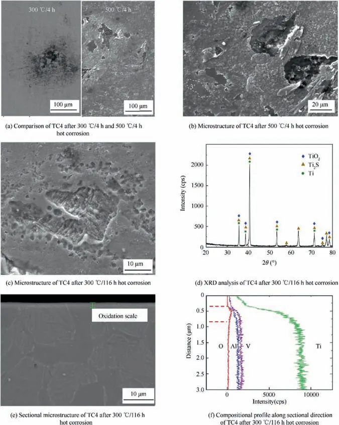
Fig. 10 Hot corrosion characteristics of TC4 substrate.

Moreover, granular oxide with the size of about 1-2 μm came into being in the unaffected region of corrosive medium in Fig. 10(b). Higher temperature accelerated the growth of oxide grains in kinetics. The oxide indicated by 3 in Fig. 10(b) had the composition of Ti-3.25Al-1.62V-63.14O-0.39Cl.It was identified as TiO2based XRD analysis. In addition,the solubility of O in β-(Ti) was less than 10% in atomic percent according to Ti-O phase diagram,15but the solubility of O in α-(Ti) was more than 30% in atomic percent. When the amount of diffused O exceeded the solubility, this would lead to the formation of oxide on its surface. This could explain why different regions had varying degrees of oxidation,so significant oxidation scale was in line with the β-(Ti) in the TC4 substrate, and the surface of α-(Ti) indicated by 3′did not clearly change due to its high O solubility and thin oxidation film. Fig. 10(c) was the microstructure of TC4 after 300°C/116 h hot corrosion,which was even more serious than 88 h hot corrosion analyzed in anther paper.26Fig. 10(d) was the XRD result of TC4 after 116 h hot corrosion. Reaction product such as soluble MCl2, titanate anion and aluminate anion were removed at the cleaning corrosive medium time.The remaining oxide TiO2and sulfide Ti2S were identified accordingly. Fig. 10(e) and (f) were the sectional microstructure and the compositional profile along the sectional direction of TC4.It could be seen that corrosion and oxidation along the vertical direction was not serious;thin oxidation scale less than 1 μm was formed after 300°C/116 h, so hot corrosion was mainly on the surface.
4. Conclusions
The corrosion behaviors of TC4 alloy and TiN/Ti coating were investigated systematically with salt spray corrosion and hot corrosion. The driving forces of Ti and TiN oxidation were thermodynamically calculated according to the service conditions of compressor blade.The findings in this work were summarized as follows:
1) High pressure had negligible effects on the Gibbs energy change of Ti and TiN oxidation.The phase diagram calculation illustrated TiN could coexist with multiple Ti oxide under high pressure, which could affect the adhesion and increase the stress between the coating and substrate.
2) In the process of salt spray corrosion, the corrosion potential difference of TiN and Ti promoted the pitting corrosion in the multilayer coating; the defect regions with large grains and the defects-free coating also promoted local galvanic corrosion due to both compositional difference and electrochemical stability difference.
3) For TC4 alloy,obvious passive film appeared after 960 h salt spray corrosion.When the formation of passivation film was unsustainable, the destroy of passive film was observed.
4) Hot corrosion time increased the amount and size of corrosions for TiN/Ti coatings.Owing to the disordered state associated with the columnar boundary and the coating defect,nitrogen could be easily replaced by oxygen.These structures were channels for fast diffusion of oxygen.This promoted stratification along the columnar boundary.
5) For TC4 alloy,higher temperature suffered more serious corrosion and rougher corrosive surface; some corrosions occurred under the deposition of corrosive medium due to the formation of soluble chloride, titanate anion and aluminate anion.
Acknowledgements
This work was supported by National Science and Technology Major Project of China(2017-VII-0012-0107),National Natural Science Foundation of China (No. 51405506) and Natural Science Basic Research Plan in Shaanxi Province of China(No. 2019JQ-309).
 CHINESE JOURNAL OF AERONAUTICS2020年6期
- CHINESE JOURNAL OF AERONAUTICS的其它文章
- A novel variable structure multi-model approach based on error-ambiguity decomposition
- Multi-block SSD based on small object detection for UAV railway scene surveillance
- A new online modelling method for aircraft engine state space model
- Cross-sectional deformation of H96 brass double-ridged rectangular tube in rotary draw bending process with diあerent yield criteria
- Application of a PCA-DBN-based surrogate model to robust aerodynamic design optimization
- Numerical exploration on the thermal invasion characteristics of two typical gap-cavity structures subjected to hypersonic airflow
