Numerical exploration on the thermal invasion characteristics of two typical gap-cavity structures subjected to hypersonic airflow
Zhenhuan LI, Xinlin XIA , Xiaolei LI, Chuang SUN
Key Laboratory of Aerospace Thermophysics of Ministry of Industry and Information Technology, School of Energy Science and Engineering, Harbin Institute of Technology, Harbin 150001, China
KEYWORDS Gap-cavity structure;Heat transfer;Hypersonic flow;Porous material;Thermal invasion
Abstract In this paper,numerical investigation of hypersonic gas flow over two typical gap-cavity structures is carried out using all-speed preconditioned density-based solver. Such structures filled with porous seal in the gap are often present at the joint locations of control surfaces of the hypersonic vehicles. Single-domain approach is adopted to integrate the governing equations for both porous and fluid regions.The basic thermal invasion characteristic is first illustrated using the maze gap-cavity structure without sealing.Then,the influence of seal filling depth on the thermal invasion characteristic is investigated for the structure with sealing. Finally, a comparison of thermal invasion characteristics between maze and straight gap-cavity structures is performed to examine the influence of gap bending. Results show that the main source of hot airflow invading into the gap is from the millimeter scale gas layer within the boundary layer.And the invasion characteristic presents approximate stationary behavior.A primary vortex occurs in the gap adjacent to the leeward wall, which is ascribed to the impinging effect between the separate boundary flow and the windward wall. This effect is also the main driving force of thermal invasion. A treatment of filling the seal in certain depth inside the gap can significantly reduce the thermal load of seal and maintain an acceptable level of the invading mass flow rate. Additionally, it is found that the gap bending exerts a limited block effect on the thermal invasion without sealing,and this effect can be ignored with sealing.These results can provide a reference for optimizing the seal gap-cavity structure configuration.
1. Introduction
During atmospheric reentry, space shuttles experience heavy aerodynamic thermal loads.1-3To reduce that, the Thermal Protection System (TPS) must be installed to reduce the unit volume of thermal payload.4Link structures are usually observed among the conjunctions of the TPS panels or flight control surfaces. The hostile aerothermal condition may impose great challenge for these structures because the external hot airflow can intrude into the gaps through the filled seal porous.Thus,it is possible to break the integrity of the vehicle once the structures underneath the gaps are overheated.
Since the disaster of the Space Shuttle Challenger in the 1980s, there has been increasing focus on the seal structures.In the early 2000s, NASA launched a series of experiments to test the seal design of the reentry vehicles. Dunlap et al.5,6conducted the thermal analysis, flow, scrub and compression test on the seals for the rudder/fin and control surface location of the X-38. They discovered a significant temperature drop(up to 1205.4 K) across the seal, which suggests the necessity to fill the rudder/fin gap with seals. Taylor et al.7reported the high temperature compression test (up to 1366.5 K) on a variety of seals using spring tubes as the resilient element.The testing results showed that the resiliency could be improved by optimizing the spring tube geometry. Finkbeiner et al.8showed the performance of a unique apparatus which can test a variety of seal designs with the capability of manipulating the flap position. As the wafer seal is promising for movable link structures,9DeMange et al.10performed high temperature scrub tests. Both high friction force and material transfer phenomenon were found between the wafer seals and the carbon-silicon surfaces. In addition, the performance of spring tube thermal barriers and innovative wafer seal systems were also assessed by the high temperature compression and room temperature tests. Phillips and Wingate11evaluated the capabilities of the candidate seals that can be used in the Ares-I seal joints for the Ares-I Upper Stage LOX Tank.The deflections of the corresponding joint components were analyzed. Their results showed that the RACO seal may be more suitable for the sump seal joint.
It is found that current investigations mainly concentrate on revealing the mechanical performances and penetration properties of seals via experimental methods. However, there is lacking of CFD simulations of heat and flow transport in the seal structure.Buning et al.12performed the only numerical work about the seal structure that described several CFD methods to predict the separation of ‘‘Hyper-X” hypersonic vehicle from the launch vehicle. They first obtained the converged external flow field with the gap ‘‘sealed” and subsequently solved the gap flow with very low Mach number and freestream static pressure.
So far, a number of numerical works on high speed flows over cavities emerge. Xu et al.13predicted the effects of angle of attack, Mach number and width-to-depth ratio of gap on the local aerodynamic heating by the finite volume method.Huang G and Huang HM14numerically investigated the deep gap flow field under a hypersonic airflow condition. Their computer codes considered both the chemically reacting and the all-speed-regime of the flow field. They revealed a ‘‘U”shaped distribution of heat flux in the gap. As the re-entry vehicle is usually associated with rarefied hypersonic flows,quite a few researchers also employed the Direct Simulation Monte Carlo (DSMC) method to study the hypersonic cavity flows. Leite and Santos15analyzed a hypersonic flow over a combined gap and step configuration at zero angles of attack.Effects of freestream Mach number and the step frontal-face height on the pressure and heating loads were carried out in their work. Jin et al.16investigated rarefied hypersonic flows over 2D and 3D cavities on a flat plate for a wide range of angles of attack. They found that a second vortex system is formed inside the cavity when the angle of attack is increased to 30°. Palharini et al.17investigated rarefied hypersonic gas flow over 3D cavities in the presence of chemical reactions.The effect of variable length-to-depth ratios on the flow topology inside the cavity was exhibited.
In spite of the substantial research on the properties of seal structures18and high speed flows over cavities,the invasion of external airflow into seal gap-cavity structures is barely studied.19Although our team published relevant works,20,21the freestream static pressure is noticeably higher than the initial pressure inside the inner cavity.This may deviate from the real situation. And more importantly, the configurations are confined to straight gap, but the upper gap of a real structure may be designed as zigzag with seal filled deeply inside it.This shape can prevent the hot boundary layer thermal shock confronting the seal directly. On the other hand, a zigzag gap is more suitable for the conjunction of different substructures.One typical example can be found in the seal test apparatus reported by Dunlap et al.22Therefore, it is urgent to conduct thermal invasion analysis for the link structures with a zigzag gap configuration.
The objectives of this paper are firstly, to reveal the basic thermal invasion characteristics for the gap-cavity structure subjected to hypersonic airflow under no-sealing condition.Secondly, to analyze the impacts of variable inserted depth of seal on the thermal invasion characteristics and figure out the feasibility of filling the seal inside the gap deeply. Finally,to explore the differentials in thermal invasion characteristics of two typical structures due to the bent topology of gap.So,the paper is organized as follows.In Section 2,the problem is stated and its governing equations are introduced. In Section 3, we present the numerical method and validate it. Section 4 gives the results and findings. The paper finalizes with the main conclusions in Section 5.
2. Problem statement
2.1. Problem description
Two configurations of gap-cavity structures are considered in this paper as shown in Fig.1.The first configuration is the typical straight gap structure. The striking feature of the second one exhibits on the upper bending gap. Moreover, it should be noted that both configurations may be filled with porous seal inside the gap and the distance Δy from the seal to the gap entrance is changeable.The length of porous seal in depth is 10 mm. The whole fluid domain contains upper high speed region(external fluid field)and inner low speed region(cavity).The two fluid regions are connected by the gap, the width of which is 2 mm. The solid structure consists of thermal protective material(Material 1)and insulation material(Material 2).The height Heand width W of the structure are 200 mm and 180 mm, respectively. The relative dimensions of the components with respect to that of the square enclosure are marked in detail.
All the boundary conditions are also given in Fig. 1. The Mach number, temperature and static pressure in the inlet are specified as Ma∞=8.0, T∞=236.5 K, p∞=574.6 Pa.Angle of attack condition α=10°in terms of external airflow and upper solid wall is employed to study the thermal invasion effects. The initial temperature and pressure in the fluid domain are set with identical parameters.
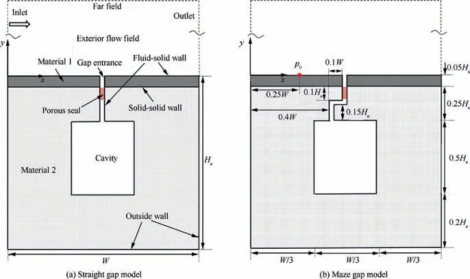
Fig. 1 Schematic diagram of gap-cavity computational model.
The Reynolds number based on the inlet condition is 2.09×10⁷m-1, thus, the flow is fully turbulent. The hybrid RANS (Reynolds-Averaged Navier-Stokes) based turbulent model k-ω SST(Shear Stress Transport)is implemented in this study,since it can use the advantages of k-ω model in the near wall region and k-ε model in the fully turbulent region at the same time.23
The outside wall enclosed the solid domain is assumed to be adiabatic. According to experiment test of our team,24the porosity φ and the permeability K of the seal is set to 0.9 and 1×10⁻⁷m2,respectively.The thermal physical properties of Material 1,Material 2 and porous seal are given in Table 1,where ρ is the density, λ is the thermal conductivity, Cpis the specific heat at constant pressure, ε is the wall emissivity.
2.2. Governing equations in fluid domain
Simulations are performed using the density-based solver for all Mach number flows in the framework of OpenFOAM.25,26It should be noted that OpenFOAM always operates in a three-dimensional Cartesian system and all geometries are generated in three dimensions. Since the 3D code has been used for the 2D simulations,a‘‘special”empty boundary condition have been specified on the top and bottom boundaries normal to the z direction with only one control volume.Single domain approach is employed to integrate both fluid and the porous region, and the interfacial effect between the two regions is neglected.Heat transfer between the invading airflow and porous seal in the gap is assumed as in a state of Local Thermal Equilibrium (LTE), i.e. the internal heat transfer coefficient hv→∞.
For the fluid region, the integration form of compressible Navier-Stokes equation introduced with preconditioned pseudotime-derivative term27can be expressed as

where Q=[p,U,T]T,W=[ρf,ρfU,ρfE]T,p is the pressure,U is the velocity,T is the temperature,ρfis the fluid density,and E is the total energy. Fcand Fvare the vector of convective fluxes and the vector of viscous fluxes, respectively. t* is the pseudotime used in the scheme of transient dual timestepping,and t denotes the physical time.dV and dS are differential volume and surface area,respectively.Γ is the preconditioning matrix28which can be written as where θ denotes the preconditioning control parameter. H denotes the total enthalpy. u, v and w are x-component, ycomponent and z-component of velocity U, respectively.


Table 1 Thermal properties of solid and porous material.
The form of governing equation for the porous region is identical to Eq. (1) except for the additional source term in the right hand,21

Nevertheless, it should be noted that partial of the components of the vectors of the temporal and spatial terms have been changed due to the inducing of porous medium and the assumption of LTE.29The vector of primitive variables for the porous region is changed as Q′=[p, φu, φv, φw, T]T. Γ′represents the preconditioning matrix for the porous region.30W′denotes the vector of conservative variables for the porous region. F′cand F′vdenote the vector of convective fluxes and the vector of viscous fluxes for the porous region,respectively.Each component of these vectors including the source term Sporin Eq. (3) is presented in the following matrix:27,29

where F′c,x, F′c,yand F′c,zare x-component, y-component and z-component of convective fluxes, respectively. F′v,x, F′v,yand F′v,zare x-component, y-component and z-component of viscous fluxes, respectively. φ is the porosity, τijstands for the component of the viscous stress tensor associated with i and j directions, μ is the dynamic viscosity, Cfis the specific heat capacity of fluid phase, ρpsand Cpsare the density and the specific heat capacity of solid phase,respectively.The effective conductivity of the porous medium, λeff=φλf+(1-φ) λps,is computed as the volume average of the fluid and solid phase thermal conductivity λf,λpsto take into account of the contribution of solid phase on the heat conduction. The subscripts‘‘f” and ‘‘ps” denote the fluid and solid phase, respectively.The momentum source term is calculated by the Darcy-Forchheimer formula to consider the drag caused by porous medium, where K and β are the permeability of the porous medium and the inertial coefficient, respectively. The relation between them can be expressed as29

The magnitude of K is determined through pressure penetration experiment. Moreover, due to the LTE assumption and no thermal radiation effect considered in the porous region, the energy source term Sφ=0. In the single domain approach, the nonporous region is also treated as a porous medium with porosity φ=1 that the influence of solid phase within it is switched off.
2.3. Governing equations in solid domain
The integral form of transient heat conduction equation in the solid domain reads

where ρsand Csrepresent the density and specific heat capacity of the solid material, respectively. n is the normal vector. The heat flux vector q can be expressed as

where λsis the thermal conductivity of solid material.
2.4. Radiative exchange calculation
All the boundary patches including the inlet, opening, outlet,and the coupled interfaces constitute an enclosure. Only surface-to-surface radiative heat transfer is considered here.Fluid-solid coupled interfaces are treated as diffuse-gray surfaces.To make a radiative heat transfer balance on surface element j, the incident radiation heat flux Gj, effective radiation heat flux leaving the surface Jjand remaining heat flux qjcan be expressed as follows


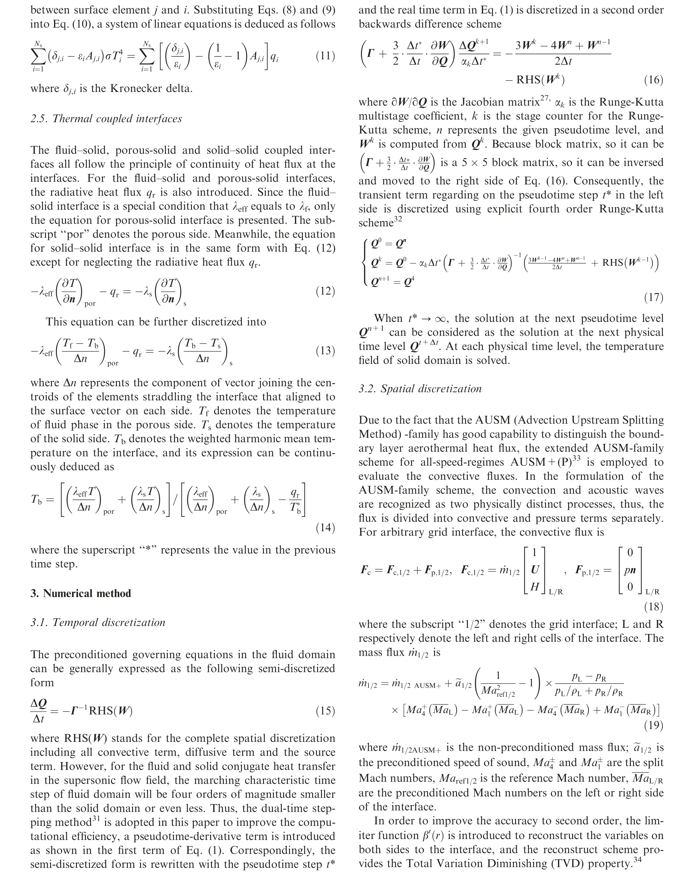
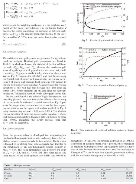
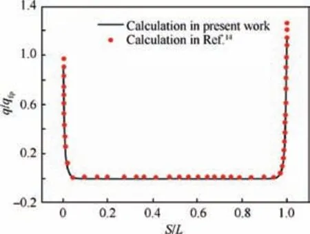
Fig. 5 Comparison of dimensionless heat flux within deep gap.
The other one is concentrated on gap flow under a hypersonic air flow condition. The parameters of free stream are Ma∞=12.0, Reynolds number Re=6.4×10⁵m-1,T∞=73.4 K,and density ρ∞=1.55×10⁻³kg/m3.The angle of attack is 0°. All the walls including the inner gap are assumed as isothermal, Tw=288.15 K. The dimensionless wall heat flux q/qfpinside the deep gap is extracted and compared with those obtained in Ref.14, where q is the heat flux in the gap, qfpis the corresponding heat flux on the flat plate,S/L is the dimensionless length along the gap wall,S is the distance from leeward upper corner point along the gap wall in an anti-clockwise direction, L is the total length of the gap wall.As shown in Fig. 5, it can be seen that the agreement is excellent.
4. Results and discussion
4.1.Thermal invasion characteristic of structure without sealing
The transient results for the maze structure without sealing are first presented here to illustrate the thermal invasion characteristic around the gap entrance.As observed vividly from Fig.6,one can find that the external flow sucked into the gap is mainly from the external boundary layer.Meanwhile,the temperature level of the invading gas flow is in the same order of magnitude with the millimeter scale height gas layer.A relative low temperature region is discovered adjacent to the leeward wall, which is caused by the local vortex. And the formation mechanism will be detailed explored in the later section. The hot gas flow invades into the gap and heats the solid regions located on both sides. With the increasing of invasion depth,the temperature level of local gas flow gradually decreases because the heat is transferred to the solid regions via convective heat transfer. Moreover, according to the high temperature contour at different moments, it can be speculated that the thermal invasion characteristic of the hot gas flow along the gap entrance is nearly unchanged.
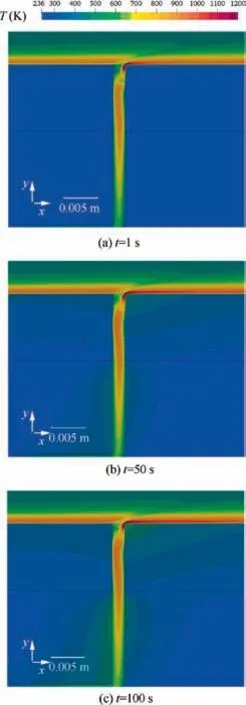
Fig. 6 Transient temperature contours around gap entrance region of structure without sealing.
Fig. 7 gives the variable distributions along the gap entrance of the structure without sealing corresponding to the different moments. These variables include mass flux, yaxis velocity, temperature and pressure. Overall, it confirms that the non-stationary behavior of thermal invading along the gap entrance is not significant as all the variables change slowly with transient process proceeding. Among them, the amount of mass flow rate can be viewed as the major indicator of intensity of thermal invasion. Since the mass flow rate are determined by both the local airflow density and magnitude of y-axis velocity, the distribution of this variable follows an analogous tendency with Uy. For both of these two variables,it can be found that the shapes of the curves exhibit a main platform followed by drastic decrease close to the right wall of the gap. This ‘‘platform-valley-behavior” is caused due to the fact that the external flow collides intensely with the windward wall when the angle of attack is non-zero.Because of the compression effect,minimal local gas is pushed out of the gap,and the peak value of the Uyis nearly 100 m/s in positive y-axis direction.Accordingly,Fig.7(c)and(d)show that there exists drastic increase of local static temperature and pressure around this region.
4.2. Influence of porous seal filling depth on thermal invasion characteristic
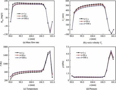
Fig. 7 Transient variable distributions along gap entrance for maze structure without sealing.
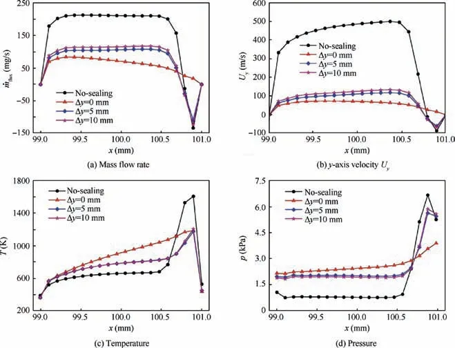
Fig. 8 Comparison of variable distributions along gap entrance for structure with different seal inserted depths at t=100 s.
Since the seal is not made up of thermal protective composites,filling it deeply inside the gap provides a way to alleviate the self-thermal load.Nevertheless,the filling depth may influence the thermal invasion characteristic. Under the sealing condition, taking the maze gap as an example, the influences of the filling depth of the porous seal on the thermal invasion characteristic are discussed.
Fig. 8 compares the distributions of these variables along the gap entrance for three different seal filling depths(Δy=0, 5, 10 mm) as well as those of the structure without sealing at t=100 s. For the inserted sealing conditions(Δy >0 mm),it can be observed that the distributions of variables along the gap entrance are generally located between those of no-sealing and embedded sealing conditions(Δy=0 mm).Meanwhile,the filling depth of the inserted condition does not exert a noticeable influence on the magnitude.
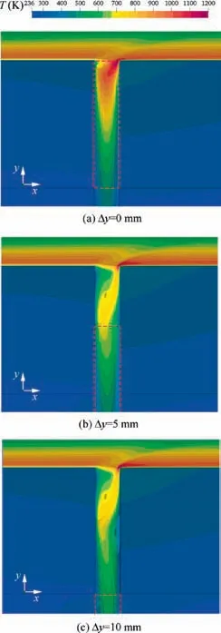
Fig. 9 Temperature contours of gap entrance region of maze structure with different seal inserted depths at t=100 s.
Regarding on the mass flow rate and y-axis velocity distributions, this means that the thermal invading resistance induced by the inserted sealing condition is inferior to the embedded one. Despite of that, compared with the nosealing condition,the mass flow rate through the gap entrance for all the three sealing conditions are decreased considerably.To be specific, the mean magnitude of the mass flow rate for the embedded sealing condition is 36.9% of that without sealing, and the same for the inserted sealing condition(Δy=10 mm) is 50.5%. The discrepancy regarding on mass flow rate between these two conditions can be reflected by the corresponding static pressure distributions. As shown in Fig. 8(d), regardless of the region close to the right wall, the mean pressure for embedded sealing condition is the highest with the value being triple of that of the no-sealing condition,and it is followed by the two inserted sealing conditions. The mean pressure for the latter two conditions is almost identical,with the value being 2.5 folds of that of the no-sealing one.Since the higher pressure indicates the higher flow resistance through the gap, the distributions represent a reverse order of those corresponding to the mass flow rate. Fig. 8(c) compares the temperature distributions for all the conditions. It is reasonable to see that the peak behavior of the temperature distribution close to the right wall tends to be gentle under the sealing condition.This is because the porous material will exert additional drag forces on the external flow when it collides with the windward wall. During the transport process, partial of the kinetic energy of the flow is converted into internal energy resulting in higher level of temperature distribution along the gap entrance.And the phenomenon of the embedded sealing one seems more obvious.
In order to further comprehend the thermal invading mechanism around the gap entrance region for different seal filling depth conditions,the corresponding temperature contours and flow field inside the gap at t=100 s are displayed and compared in Fig. 9. It should be noted that the regions enclosed by the red dashed line inside the gap are occupied by the porous seal.One major finding from Fig.9 is the existence of recirculation structures inside the gap. The streamline patterns show that the flow has a primary vortex around the leeward wall for all the three situations. Obviously, this recirculation zone is caused by aforementioned impinging effect between the separated boundary flow and the windward wall. This effect results in local high pressure region.The pressure differential between this region and the inner cavity is much larger than that adjacent to leeward wall, which forces more airflow penetrating into the gap. On the other hand, the high speed external flow across the gap entrance also results in a clockwise driving force on the gap flow. The conjunction of these two mechanisms gives rise to this special flow topology.Moreover,it is interesting to notice that the filling depth of the porous seal can influence the size of recirculation zones.Under the embedded condition, the primary vortex region is significantly reduced in comparison with the latter two cases. This is because the porous material has a strong function in redistributing the flow.37However,it is important to highlight that the embedded porous seal will be subjected to severe thermal loading directly. And this could promote damage to the seal in a short time during reentry.
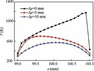
Fig. 10 Comparison of temperature distributions along up interface of seal under different inserting depths at t=100 s.
To concretely assess the thermal environment,Fig.10 compares the temperature distributions along the up interface of the porous seal under three different inserted depths at t=100 s. As expected, the embedded porous seal will suffer the toughest aerodynamic heating, and the region close to the windward wall is even worse due to the compression effect.In comparison with the embedded situation, the magnitude of mean temperature on the interface is declined significantly for the inserted cases.For the case when the porous seal is inserted 10 mm, the magnitude is merely half of that of embedded situation. And the profile turns out to be symmetric because the up interface is far from the vortex disturbing region for this situation.
Due to the fact that there are recirculation zones inside the gap near the entrance, three mass flow rate profiles on the down interface of the porous seal are compared in Fig. 11 to evaluate the amount of mass flow into the cavity. Meanwhile,the mass flow rate on the cross-section undisturbed by the recirculation zone for the no-sealing condition is extracted as a reference.Similar to the distributions along the gap entrance in Fig. 8(a), for all the sealing conditions, the mass flow rate into the cavity decreases substantially compared with the nosealing condition.A decrease of approximately 50%regarding on mean value is observed for the case when the seal is inserted 10 mm.Although the mass flow rate further decreases with the inserted depth decreasing, the decline is not obvious.
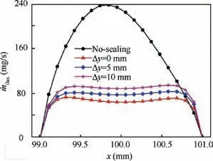
Fig.11 Comparison of mass flow rate distributions along down interface of seal under different insert depths at t=100 s.
4.3. Comparison of thermal invasion characteristics of two typical structures under sealing and no-sealing condition
According to the analysis of former section, it can be argued that filling the porous seal in certain depth inside the gap can be a good trade-off between the two requirements, i.e.reducing the thermal load of porous seal and alleviating the thermal invasion into the cavity. In this section, we focus on figuring out whether the gap bending is a feasible way to delay the thermal invasion process by comparing the thermal invasion characteristics of two typical structures.
The no-sealing condition is firstly carried out.Fig.12 compares the distributions of mass flow rate and temperature along the gap entrance for both straight and maze gap structures at different moments. It is clear that the mass flow rate through the straight gap is slightly higher than that of maze gap because of the blocking effect of the zigzag gap underneath. At t=100 s, the relative average difference between these two structures is 7.4%.By contrast,Fig.12(b)shows that the mean temperature along the entrance of maze gap is 3.2%higher than that of straight gap. This indicates that the influence on the entrance temperature distribution is smaller.Actually, the discrepancy in pressure distributions around the entrance gap region yields mass flow rate difference.As shown in Fig.13,one can find that the pressure contours corresponding to two gaps are slightly different.For the maze gap,Fig.13(b) indicates that the region marked as ranging from 1500-2000 Pa is more close to the gap entrance in comparison with the straight gap. This again demonstrates the block effect of maze gap under such condition.
With the seal filling 10 mm depth inside both the straight gap and maze gap,the distributions of mass flow rate and temperature along the gap entrance are presented in Fig.14.Obviously,it is found that the mass flow rates through the two gap entrances turn out to be consistent after filling the seal. This phenomenon can be explained as follows. When the external airflow enters the gap filled with seal, the y-axis velocity is decelerated drastically,and the mass flow rate through the seal into the below zigzag gap becomes appreciably smaller compared with the no-sealing one.Since the gas momentum inside the gap underneath the seal are both small for the two cases,the flow resistance generated by the maze gap is no longer obvious under the circumstances. In other words, it can be remarked that the limited block effect of the maze gap is buried under the noticeable block effect of the porous seal. In accordance, as shown in Fig. 14(b), we found no differences exhibited between the temperature distributions for the two cases.Once again,the pressure fields presented in Fig.15 confirm above analysis. This figure highlights that the region marked as ranging from 2000-2500 Pa is almost in the same location and size,which means the driving pressure differential for the two cases is close.
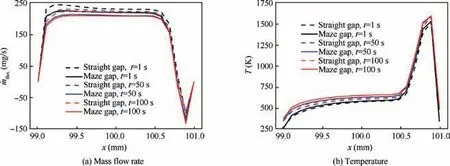
Fig. 12 Comparison of mass flow rate and temperature distributions along straight and maze gap for structure without sealing.
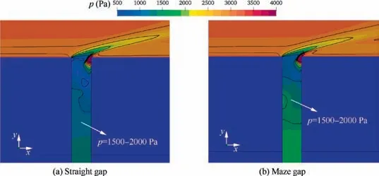
Fig. 13 Comparison of pressure contours around straight and maze gap entrance for structure without sealing at t=100 s.
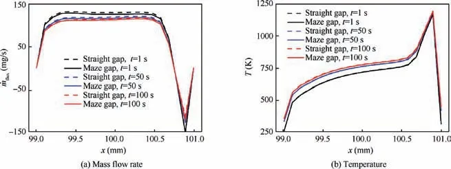
Fig. 14 Comparison of mass flow rate and temperature distributions along straight and maze gap for structure with sealing.
Fig. 16 compares the temperature contours of the whole cross-section for both straight gap and maze gap structures with or without sealing at t=100 s. Firstly, it is seen that the porous seal exerts a noticeable block effect on the boundary layer hot airflow invading into the inner cavity.Regardless of the gap topology, it is observed that the temperature magnitudes in the cavities with sealing are much lower than those of no-sealing ones. This confirms that filling the porous seal deeply inside the gap will not impair its delaying thermal invasion characteristic considerably.On the other hand,comparing Fig. 16(a) and (b), slightly higher temperature magnitude inside the cavity is observed for the straight gap one. The reason can be ascribed to both the block effect and the increased heat transfer area of the maze gap.Obviously,more heat of the thermal boundary flow is transferred to the slot wall inside maze gap due to its tortuosity. In addition, for the nosealing condition, the temperature fields inside the cavities of both the straight gap and maze gap structures are disordered because of the existence of jet impingement effect inside the cavity. By contrast, the symmetric temperature field inside the cavity shown in Fig. 16(c) indicates the porous material is able to regularize the gap flow and reduce the jet impingement significantly.
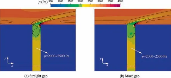
Fig. 15 Comparison of pressure contours around straight and maze gap entrance for structure with sealing at t=100 s.
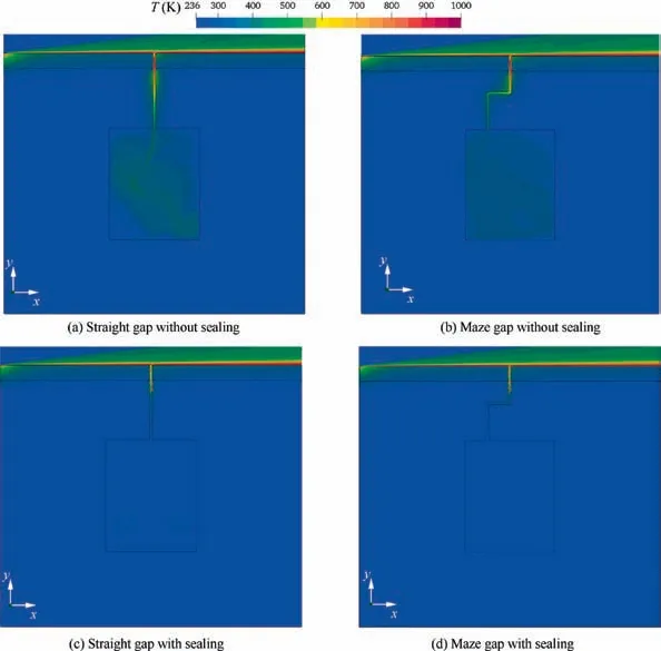
Fig. 16 Comparison of temperature contours of entire structure at t=100 s.
5. Conclusions
The numerical simulations of supersonic gas flow over two typical gap-cavity structures were performed.Firstly,the basic thermal invasion characteristic is illustrated using the structure with no-sealing.Then,the influence of seal filling depth on the thermal invasion characteristic is carried out under the sealing condition.Finally,the thermal invasion characteristics regarding on both the maze gap and straight gap structures are compared under sealing and no-sealing conditions to analyze the influence of gap bending.The following conclusions have been drawn:
(1) The gas flow invading into the gap through suction effect is mainly comprised by the millimeter scale height hot gas layer within the external boundary layer.Meanwhile,with the transient process proceeding,all the variables relevant to the thermal invasion characteristic along the gap entrance tend to be stationary.
(2) A primary vortex adjacent to the leeward wall is discovered for all the situations with and without sealing.This recirculation zone is caused by the impinging effect between the separated boundary layer flow and the windward wall. Meanwhile, it also leads to a local high pressure region. The pressure differential between this region and the inner cavity is the main driving force of the thermal invasion.
(3) Filling the porous seal in certain depth inside the gap provides a good way to reduce its thermal load and delay the thermal invasion process. Compared with the normal embedded condition, a decrease about 50% of the mean temperature magnitude is achieved at t=100 s for the case when the seal is inserted 10 mm.In addition, the mass flow rate is not observed to increase considerably through the porous seal.
(4) Under the condition of no-sealing, the structure with maze gap exerts certain resistance on the thermal invasion in comparison with that using a straight one. A 7.4% mass flow rate differential exists between the two cases.However,the limited block effect can be neglected when both of the structures are filled with seal.
These findings can provide some useful information for multi-objective optimization of the gap-cavity structure in the future, which is aimed at satisfying both minimum invading mass flow rate and thermal load of the seal simultaneously.
Acknowledgement
The work was supported by the National Natural Science Foundation of China (No. 51536001 and No. 51776053).
 CHINESE JOURNAL OF AERONAUTICS2020年6期
- CHINESE JOURNAL OF AERONAUTICS的其它文章
- A novel variable structure multi-model approach based on error-ambiguity decomposition
- Multi-block SSD based on small object detection for UAV railway scene surveillance
- A new online modelling method for aircraft engine state space model
- Cross-sectional deformation of H96 brass double-ridged rectangular tube in rotary draw bending process with diあerent yield criteria
- Application of a PCA-DBN-based surrogate model to robust aerodynamic design optimization
- Experimental study on plasma jet deflection and energy extraction with MHD control
