Experimental study on plasma jet deflection and energy extraction with MHD control
Ki ZHAO, Ming MING, Feng LI, Yongji LU, To ZHOU,Kefu WANG, Nn MENG
a School of Energy and Power Engineering, Beihang University, Beijing 100083, China
b School of Aviation Operations and Services, Aviation University of Air Force, Changchun 130022, China
KEYWORDS Energy extraction;Flow control;Jet deflection;Magneto-hydrodynamics;Plasma
Abstract This paper presents an integrated research scheme for vector deflection and energy extraction in a gas plasma jet under Magneto-Hydrodynamic (MHD) control. A MHDcontrolled thrust-vector test rig was used to conduct the experimental research. A gas plasma was obtained by injecting ionization seeds of Cs2CO3 into the combustion chamber via artificially forced ionization. The effects of the gas temperature and ionization seed mass fraction on the plasma jet deflection and energy extraction were experimentally verified under an applied magnetic field. The experimental results were analyzed theoretically. The results showed that the deflection amplitude of the gas plasma jet and the extracted voltage signal intensity increased with increasing gas temperature and the ionization seed mass fraction. The extracted dynamic voltage signals proved that the ionization seeds of Cs2CO3 induced gas ionization at 1173 K. The experiment verified that it is feasible to simultaneously achieve jet deflection and extract energy under the action of an external magnetic field.
1. Introduction
Thrust-vector technology is considered a key technology for future fighters, and thrust vector performance is an important index for evaluating high-performance fighters; this topic has attracted great attention from military forces worldwide.Thrust-vector control methods include mechanical control,pneumatic control, and electromagnetic control. Mechanical hydraulic control has the disadvantages of complex structures and heavy accessories, which reduces the reliability and maintainability of the system. However, pneumatic control consumes large amounts of compressed air, which reduces the efficiency of the engine and increases the cost.1
Thrust-vector technology controlled by electromagnetism is based either on the Electro-Hydrodynamic(EHD)principle or the Magneto-Hydrodynamic (MHD) principle. The plasma generated by Dielectric Barrier Discharge(DBD)is accelerated by a high-voltage electric field to reduce fluid drag and prevent flow separation based on the EHD principle.2-4Most of the research in this field has focused on boundary layer flow control.5,6In MHD, a magnetic fluid is used and this technology has been used in power generation, aviation, navigation, and other fields;7-9the main focus has been on MHD flow control,10,11MHD acceleration,12,13MHD power generation,14-17and MHD combined engines.18Sun19and Luo20et al. conducted experimental studies on the deflection of a gas plasma jet by injecting Cs2CO3ionization seed into a combustion chamber under an external magnetic field. Zhao et al.21conducted a study of jet deflection of gas plasma under an external magnetic field using numerical simulations and experiments.Lineberry et al.22carried out an experimental study on the extraction of electrical energy from high-temperature gas plasma using a coupled electric field and magnetic field. In the Hypersonic Vehicle Electric Power System(HVEPS)23ionization seeds were injected during combustion to improve gas ionization and obtain gas plasma;electric energy was extracted under a high-intensity magnetic field.Compared with the traditional thrust-vector control method, the MHD flow control method includes a control device inside the body of the aircraft to avoid the influence of the control mode on engine operation.The effect of adding ionization seed depends on the spatial distribution of the ionization seed. The plasma produced by this method has a wide distribution range equivalent to that of the ‘‘whole” plasma. The action area of magnetic field is also wider, and the energy management scheme is more feasible than that of in traditional thrust-vector control methods. The design does not require the aircraft to be equipped with additional air intake/exhaust devices,which is conducive to attaining a compact design of the aircraft and the engine structure and meeting high-performance engine requirements.Therefore,the use of MHD technology for the simultaneous achievement of engine flow control and energy extraction has significant promise for practical applications.
In this paper, an MHD-controlled plasma flow deflection and energy extraction scheme is proposed. First of all, the experimental system and method are described. Next, the effects of the gas temperature and ionization seed mass fraction on the MHD flow control and energy extraction are investigated using an MHD control test rig. The experimental results are theoretically analyzed and discussed. Finally, the paper is summarized, and conclusions are drawn.
2. Experimental system and method
2.1. Experimental device
The experiment was carried out on an MHD-controlled thrustvector test rig.The test rig consisted of an air source platform,a flow control platform, and a measuring system. The experimental system is shown in Fig. 1. High-speed and lowtemperature gas plasma was used as the experimental working fluid. A comprehensive experimental scheme consisting of gas supply, combustion heating, seed-induced ionization and accelerated flow in a Laval nozzle was developed to meet the experimental requirements.
2.1.1. Gas source platform
The gas source platform provides high-speed and lowtemperature gas plasma as an experimental working fluid.Considering the high-temperature environment and the need for insulation in the experiment, the combustion chamber,nozzle, and experimental section of the gas source platform consisted of a double-layer casing.The inner layer of the bushing was a high-temperature resistant ceramic bushing, which reduced the effects of heat on the experimental system and met the insulation requirements. The outer layer of the casing was made of non-magnetic austenitic stainless steel and was connected to the ceramic experimental parts. The parameters of the platform components are shown in Table 1.
A compressor with a flow rate of 0.25 kg/s and a maximum pressure of 2 atm (1 atm=105Pa) provided compressed air.The air flow was controlled by an orifice throttling device.The combustor structure adopted swirling air intake mode combined with centrifugal atomizing nozzle fuel injection combustion. Compressed air entered the combustion chamber at the head of the cyclone. A Denver fuel nozzle was installed in the center of the cyclone.The gas temperature was measured by a thermocouple installed at the exit of the combustion chamber. The gas temperature was regulated by controlling the fuel supply and the experimental temperature was maintained between 900 K and 1300 K. The injection interfaces of the ionization seed were installed on the left and right walls of the combustion chamber. The igniter was mounted on the upper wall of the combustion chamber. The contraction section of the Laval nozzle was converted from square to rectangle to weaken the three-dimensional turbulent characteristics of the air flow at the nozzle inlet. The expansion section of the Laval nozzle had an equal width and variable height to enhance the two-dimensional characteristics of the air flow at the nozzle outlet.Five static pressure measurement points were arranged along the flow direction on the lower side wall of the gas source platform. A constant cross-section cuboid channel was used in the experimental section. Copper electrode plates were installed on the upper and lower walls of the passage and ceramic insulation planes were arranged on the left and right walls.24The schematic diagram of the experimental system is shown in Fig. 2.
2.1.2. Flow control platform
The flow control platform consisted of an ionization seed fluidization device and a magnetic control device. The seed fluidization device fluidized the powdered Cs2CO3with highpressure air and then sprayed the seeds into the combustion chamber from the side interface of the combustion chamber.In the experimental section, a magnetic field was generated by two pairs of strong permanent magnets. The magnets were mounted at the front and back of the experimental section by a bracket. The magnetic field intensity was 0.6 T and was measured with an SG-3-B Tesla meter. The measuring area was designed as a positive pole-to-pole area, i.e., the dimensions were 170 mm (length)×130 mm (width)×120 mm (height).
2.2. Experimental process
During the experiment, the air flowed into the combustion chamber through pipes and holes. The atomized mixture of fuel and air was ignited by an ignitor, forming a hightemperature zone. At the same time, the ionization seeds were sprayed into the combustion chamber and were quickly vaporized and ionized, resulting in plasma.The experimental procedures were as follows:
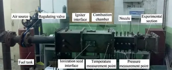
Fig. 1 MHD-controlled thrust-vector test rig.
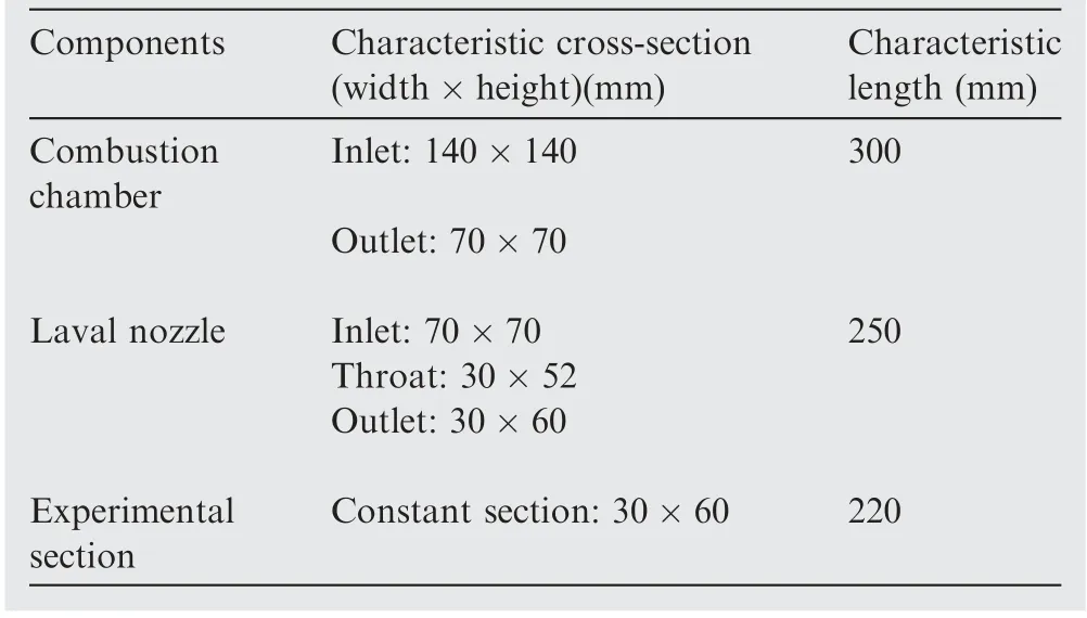
Table 1 Structural parameters of gas source platform.
Step 1. Open the high-pressure cylinder valve, increase the driving pressure of the fuel tank, open the fuel supply valve slightly, start the igniter power, and ignite the fuel.
Step 2. Start the compressor, supply air to the combustion chamber,adjust the intake valve and oil supply valve,increase the air flow and combustion chamber temperature to the experimental conditions, and record the initial thermal experimental data.
Step 3. Turn on the ionization seed Cs2CO3fluidization device switch, add the ionization seeds to the combustion chamber,and enhance the ionization characteristics of the gas.
Step 4. In the experiment, the inlet pressure of the ionization seed fluidization device was adjusted depending on the required experimental conditions, and the amount of added seeds and the experimental data of the thermal magnetic control energy were recorded.
Step 5. Turn off the ionization seed fluidization device, the fuel supply valve, and the compressor inlet valve, end the experimental process, and collate the experimental data.
3. Results and analysis
The experimental research focused on jet control and energy extraction.In terms of the engine,the former relates to energy consumption,and the latter relates to energy supply.The Cs2-CO3ionization seed induced gas ionization, and the external magnetic field controlled the deflection of the gas plasma jet to obtain a thrust vector. The voltage signals between the upper and lower electrodes of the experimental section were measured,and electrical energy was extracted.The experimental parameters are shown in Table 2.As shown in Table 2,the working condition at 973 K and without electromagnetic field is defined as MHD-01.The magnetic field perpendicular to the surface of the paper and pointed to the inside is called a positive magnetic field.The initial scheme after adding the positive magnetic field is called the MHD-02 scheme. In the experiment, the magnetic field intensity is 0.6 T.
3.1. Theoretical analysis of experiment
Charged particles were obtained when the gas was ionized at high temperature. The gas was similar to the plasma and had conductivity when the ionization degree of the gas was 10-3.The ionization degree α and electrical conductivity of the gas σ are defined as:

Fig. 2 Schematic diagram of experimental system.

Table 2 Experimental parameters.
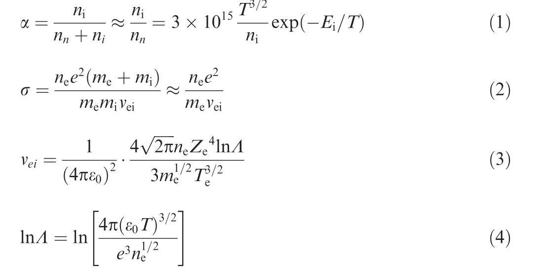
where nnis number of neutral particles per unit volume, niis number of ion particles per unit volume, Eiis ionization energy, T is Kelvin temperature. neis number of electrons per unit volume; e is electron charge; meis electron mass; miis neutron mass;veiis average collision frequency for electrons and neutrons; ε0is dielectric constant; Teis electron temperature (unit eV); Zeis ionic charge; and Λ is plasma parameter.
Considering only the Lorentz force, this force on all ions may be regarded as the volume force F produced by the fluid with MHD. Ohm’s law and electromagnetic force are expressed as follows:

where J stands for current density, V is particle velocity, B is magnetic field intensity, E is electric field intensity.
As the ionization seeds were injected into the combustion chamber, the ionization characteristics of the gas were enhanced and low-temperature plasma composed of neutral particles, electrons, and ions was formed. The positive ions rotated in a clockwise direction under the action of the Lorentz force as the positive ions entered the magnetic field.If the ions collided with a neutral particle, the momentum in the pointer direction was transferred to the neutral particle, which was deflected downward; the positive particles continued to be influenced by the magnetic field after the collision.The positive ions rotated and transferred the momentum continuously during forward movement, giving the neutral particles the flow characteristics of having been deflected downward, as shown in Fig. 3(a).
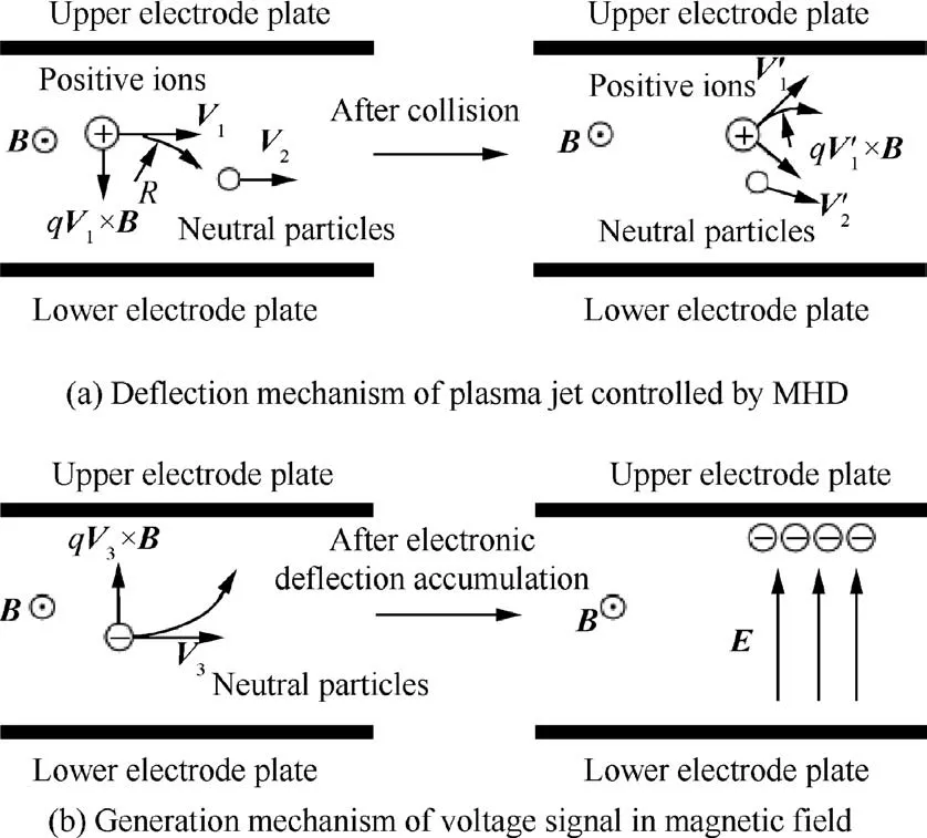
Fig. 3 Motion analysis of plasma positive ions and electrons in magnetic field.
The electrons rotated in a counterclockwise direction under the action of the Lorentz force as the electrons entered the magnetic field. Because the electron mass was much smaller than that of the positive ion, the rotation radius of the electrons was also much smaller than that of the positive ions.As such, electrons accumulated near the upper reaches of the upper electrode plate and positive ions accumulated slightly in the lower reaches of the lower electrode plate. Most of the positive ions were trapped by other mass particles. When no external electric load was applied,an electric field was induced at the lower electrode plate pointing to the upper electrode plate, exhibiting the voltage signal presented in Fig. 3(b).
The induced electric field also inhibits the rotational movement of positive ions. The movement rule of positive ions in magnetic field is determined by vectors qV×B and qE (q represents charge quantity of particle).The induced electric field is weak under the effect of no external electric field. Therefore,the gas plasma is mainly influenced by the Lorenz force, and the jet displays a certain degree of downward deflection.
3.2. Analysis of plasma jet deflection
3.2.1. Effect of gas temperature on plasma jet deflection
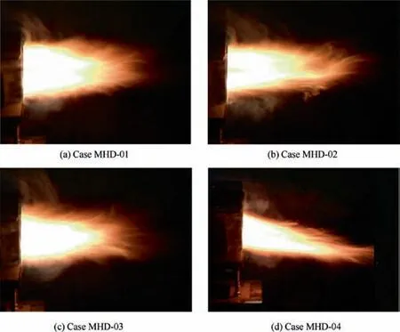
Fig. 4 Plume shape for Cases MHD-01, MHD-02, MHD-03 and MHD-04.
The influence of the gas temperature on the MHD flow control was studied experimentally.Figs.4(a)-(d)illustrate the plasma jet deflection effect corresponding to the working conditions of Cases MHD-01,MHD-02,MHD-03,and MHD-04.Figs.4(a)and (b) compare the jet deflection at 973 K with or without magnetic field. The jet deflection range is very small in both cases, mainly due to the lower gas temperature, resulting in lower gas ionization and less effect of external magnetic field.Figs. 4(c) and (d) illustrate the jet deflection with or without magnetic field at 1173 K. It is observed that at the same temperature, the plasma jet deflects after the magnetic field is applied, forming a thrust-vector effect; the higher gas temperature is, the greater the deflection range of the plasma jet is.According to theoretical Eqs.(1)-(6),the ionization characteristic of gas was enhanced with an increase in gas temperature,and the ion concentration in the gas increased, the conductivity magnitude increased. The magnetic field force and torque on the magnetic fluid increased,which caused the jet deflection angle to increase. The plasma jet deflection can also be analyzed by the static pressure on the lower wall of the nozzle.
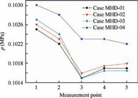
Fig.5 Comparison of static pressure on lower wall of nozzle for Cases MHD-01, MHD-02, MHD-03 and MHD-04.
Fig. 5 illustrates the comparison of static pressure on the lower wall of nozzle with or without a magnetic field at 973 K and 1173 K. The static pressure distribution indicates that the wall pressure is higher for Case MHD-04 than that for Cases MHD-02 and MHD-03, which also verifies that the downward deflection of the jet direction is larger, leading to an increase in wall pressure. Although the wall pressure for Case MHD-02 is slightly higher than that of Case MHD-01,the static pressure exhibits an increasing trend.The reason is that as the combustion temperature decreases, the conductivity of the gas plasma decreases and the effect of the Lorentz force on the plasma decreases, resulting in the weakening of the deflection effect of the jet and the decrease of the increase of static pressure.
3.2.2. Effect of ionization seed mass fraction on plasma jet deflection
At 1173 K, the gas has shown certain ionization characteristics. Therefore, it is necessary to study the effects of different ionization seed mass fractions on the MHD flow control at constant combustion temperature. The influence of different ionization seed mass fraction on the MHD flow control was investigated at 1173 K. The experimental schemes were Cases MHD-04, MHD-05 and MHD-06. The corresponding total ionization seed mass fraction was 37%, 31.3%, and 24.9%.
Figs. 6(a)-(c) indicates that at the same temperature, the higher the ionization seed mass fraction is, the greater the jet deflection is. At 1173 K, as the ionization seed mass fraction increases, the conductivity of the gas plasma increases, and the effect of the Lorentz force on the plasma increases, resulting in an enhancement of the jet deflection.For Case MHD-04 scheme, ionization seed mass fraction is the highest, so the jet deflection is the largest.

Fig. 6 Comparison of plume shape with different ionization seed mass fractions.
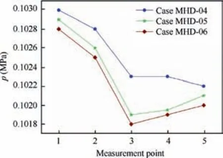
Fig.7 Comparison of static pressure on lower wall of nozzle for Cases MHD-04, MHD-05 and MHD-06.
Fig.7 compares the static pressure distribution on the lower wall of nozzle with different ionization seed mass fractions.With the increase of the ionization seed mass fraction,the static pressure on the lower wall of the nozzle also increases,which indicates that the jet deflection effect is enhanced in the downstream MHD experimental section.It also shows that increasing the mass fraction of Cs2CO3ionization seed can enhance the ionization characteristics of gas plasma. At the same temperature,the higher the ionization seed mass fraction is,the greater the jet deflection is.To a certain extent,it verifies the conclusion that the gas plasma conductivity of Cs2CO3scheme increases monotonously with the increase of the ionization seed mass fraction.
3.2.3. Effect of magnetic field direction on jet deflection
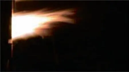
Fig. 8 Effect of reverse magnetic field on jet flow for Case MHD-07.
The experiment also verifies that the deflection direction of plasma plume changes with the change of magnetic field direction. The magnetic field direction of scheme Case MHD-04 is changed to the opposite direction,which becomes Case MHD-07 scheme shown in Table 2. Fig. 8 shows that the deflection direction of flame varies with the direction of magnetic field.This is mainly because the direction of the magnetic field has changed, and the centripetal force provided by the Lorentz force for the deflection of the magnetic fluid has changed in the opposite direction. The static pressure on the lower wall of the nozzle shows a variation law, as shown in Fig. 9. It can be seen that by changing the magnetic field in the opposite direction,the plasma jet direction deflects upward,resulting in a decrease in static pressure on the lower wall of the nozzle.
3.3. Analysis of energy extraction
3.3.1. Effect of gas temperature on energy extraction
The influence of the gas temperature on energy extraction was studied experimentally. Fig. 10 shows a comparison of the voltage signals(U)for the Cases MHD-02 and MHD-04.After voltage stabilization, the average voltage of Case MHD-04 is higher than that of Case MHD-02. Depending on the time,the voltage signals appeared as positive and negative pulses in the range of 0 to 50 s. The reasons for the pulsation signals were two-fold.
First, the magnetic field was fixed on the outside of the experimental section,and the high-temperature gas was weakly ionized, resulting in a voltage signal under the action of the magnetic field. That is, the voltage was higher on the upper side than the lower side of the electrode plate. Second, the high-temperature gas flowed through the experimental section,and the electrode plate was heated, resulting in free electron spillover from the electrode plate.In the experiment,the lower electrode plate was grounded,which favored electron spillover and a weak positive potential was observed. However, the upper electrode was equivalent to a circuit breaker without an external load and was neutral. Therefore, the voltage was higher on the lower side than that on the upper electrode plate.
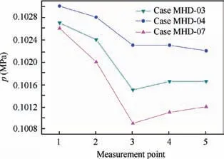
Fig.9 Comparison of static pressure on lower wall of nozzle for Cases MHD-03, MHD-04 and MHD-07.
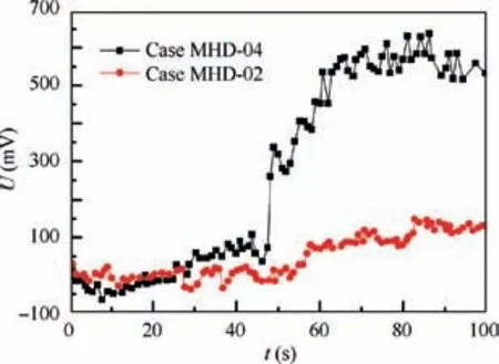
Fig.10 Comparison of voltage signals at different temperatures.
As a result, the voltage signal exhibited a positive and negative pulse state at the initial time. Near t=50 s, ionization seeds were injected into the combustion chamber. At t=50-65 s, the ionization seeds and the fluidizing gases participated in the ionization reaction and the chemical reaction in the combustion chamber,respectively.The ionization concentration in the gas increased and the voltage signal increased rapidly.After t=70 s, a balance was reached and the voltage signal stabilized. The average voltage difference was 500 mV. Therefore,the following conclusions can be drawn:for the same ionization seed mass fraction, the higher the temperature of the gas is, the higher the ionization degree of the gas is, the larger the deflection range of the plasma jet is, and the higher the voltage that extracted between the electrode plates is.
3.3.2. Effect of ionization seed mass fraction on energy extraction
The influence of different ionization seed mass fraction on energy extraction was investigated at 1173 K. The experimental schemes were Cases MHD-04,MHD-05 and MHD-06.The same temperature are more comparable. The corresponding total mass fraction of ionization seed was 37%, 31.3%, and 24.9%.
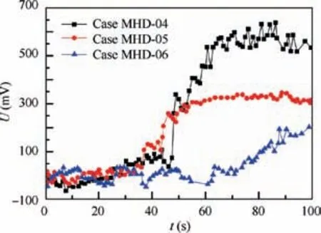
Fig. 11 Comparison of voltage signals for different ionization seed mass fraction.
Fig. 11 compares the voltage with different ionization seed mass fraction at 1173 K and 0.6 T magnetic field intensity.The average voltage values of the three schemes are 500 mV,320 mV and 100 mV, respectively. The magnitude of the voltage signal indicates that with the injection of ionization seeds,the ionization degree in the gas increases, which strengthens the ionization characteristics of the gas plasma and enhances the voltage signal.At the same temperature,the higher the ionization seed mass fraction is,the stronger the voltage signal is.In summary,as the Cs2CO3ionization seed mass increased,the jet deflection increased,and the extracted voltage signal intensity increased.
3.4. Effect of applied electric field on MHD flow control
The effect of the external electric field on the deflection of the jet was studied in this experiment. Based on the Cases MHD-03 and MHD-04,the lower electrode plate of the experimental section was connected to the positive pole of the 12 V power source, and the upper electrode plate was connected with the negative pole of the power supply, forming the Cases MHD-08 and MHD-09, respectively. Figs. 12 and 13 show the characteristics of the jet and the static pressure distribution on the lower wall of the nozzle under different combinations of the external magnetic and electric fields.
For jet deflection, Case MHD-08 has the opposite effect compared with Case MHD-04. As can be seen from Fig. 13,compared with Case MHD-03, the static pressure of nozzle lower wall in Case MHD-04 increases,while the static pressure of nozzle lower wall in Case MHD-08 decreases.However,the static pressure change of CaseMHD-04 is much larger than that of Case MHD-08. The main reason is that the induced electric field (potential difference 500 mV) in Case MHD-04 is 24 times larger than the applied electric field (potential difference 12 V) in the Case MHD-08. And the electric field is in the opposite direction. This reflects the thermal expansion effect of the external electric field on the gas plasma in the experimental section.
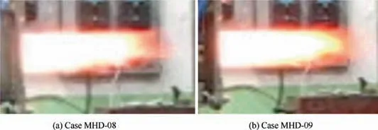
Fig. 12 Comparison of plume shape under different external magnetic and electric fields.
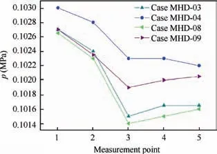
Fig. 13 Static pressure distribution on lower wall of nozzle under different combinations of external magnetic and electric fields.
For Case MHD-09, the effect of jet deflection is weaker than that of Case MHD-04. Due to the coupling effect of applied electric field and magnetic field,the static pressure distribution on the lower wall of nozzle for Case MHD-09 is between Cases MHD-04 and MHD-08.In particular,for Case MHD-09, the coupling of electric field and magnetic field accelerates the plasma flow, which makes the jet edge fuller and the flame brighter.
From the point of view of energy management, Case MHD-04 can be regarded as a gas plasma power generation process, which is related to energy extraction. Cases MHD-08 and MHD-09 are regarded as jet deflection processes controlled by external electric field or coupled electric and magnetic field respectively, which are related to energy consumption process.
4. Conclusions
This paper focuses on the integrated scheme of plasma jet deflection and energy extraction with MHD control. A thrust-vector test rig was established for experimental research.Gas plasma is obtained by injecting Cs2CO3ionization seed into the combustion chamber. The effects of gas temperature and ionization seed mass fraction on the jet deflection and energy extraction were experimentally investigated under an external magnetic field. The mechanism of jet deflection and energy extraction is analyzed. Two factors, gas temperature and ionization seed mass fraction, were discussed.
For the gas temperature, the change of temperature has a great influence on the results under the same ionization seed mass fraction. The higher the gas temperature is, the larger the deflection of plasma jet is, and the higher the voltage extracted between the electrodes is.
For ionization seed mass fraction,at the same temperature,Cs2CO3ionization seed mass fraction increased, jet deflection increased, and the extracted voltage signal intensity increased accordingly. The above results are mainly due to the increase of temperature and ionization seed mass fraction, which leads to the increase of charged particle concentration and gas conductivity. Therefore, under the external magnetic field, the Lorentz force acting on the particles increases, the jet deflection is more significant, and the voltage signal is stronger.
By configuring the external electric field, the gas plasma is heated when it flows through the MHD experimental section,which makes it expand.At the same time, the deflection effect of the plasma jet controlled by MHD is formed. Coupling the effect of external magnetic field and electric field,the deflection effect in opposite directions can be balanced, which highlights the acceleration effect of MHD on jet.
Future work will focus on the effects of magnetic field intensity on jet deflection and energy extraction.
Acknowledgement
This work was supported by the National Natural Science Foundation of China (No.90716025).
 CHINESE JOURNAL OF AERONAUTICS2020年6期
- CHINESE JOURNAL OF AERONAUTICS的其它文章
- A novel variable structure multi-model approach based on error-ambiguity decomposition
- Multi-block SSD based on small object detection for UAV railway scene surveillance
- A new online modelling method for aircraft engine state space model
- Cross-sectional deformation of H96 brass double-ridged rectangular tube in rotary draw bending process with diあerent yield criteria
- Application of a PCA-DBN-based surrogate model to robust aerodynamic design optimization
- Numerical exploration on the thermal invasion characteristics of two typical gap-cavity structures subjected to hypersonic airflow
