Cross-sectional deformation behavior of double-ridged rectangular tube with fillers in diあerent stages of H-typed bending
Chunmei LIU, Yuli LIU,*
a Research & Development Institute of Northwestern Polytechnical University in Shenzhen, Shenzhen 518057, China
b State Key Laboratory of Solidification Processing, School of Materials Science and Engineering, Northwestern Polytechnical University, Xi’an 710072, China
KEYWORDS Cross-sectional deformation;FE simulation;H96 double-ridged rectangular tube;H-typed rotary draw bending;Ridge groove fillers;Twice-springback stage
Abstract The bent double-ridged rectangular tube(DRRT)with high forming quality is helpful to improve the microwave transmission accuracy.For reducing the cross-sectional deformation in the H-typed bending process, in addition to using rigid mandrel to support the inside of tube, ridge groove fillers are also added to restrict the deformation of ridge grooves. Because of the change of stress and strain state of bent tube in bending, rigid mandrel retracting and specially twicespringback stages, and the springback of fillers, the cross-sectional deformation of tube in each stage may be different. Therefore, based on the ABAQUS platform, the finite element models(FEM) for H-typed bending, mandrel retracting and twice-springback stages of H96 DRRT with fillers were established and validated.It is found that,for the height and width deformation of tube and spacing deformation of ridge grooves,retraction of mandrel can make the distribution of these deformations more uniform along the bending direction. The first springback can reduce these deformations significantly, which should be emphasized. But the second springback only increases them by less amount, which can be ignored. The smaller height deformation of ridge groove and filler can be neglected.
1. Introduction
With the advantages of lower cut-off frequency,wider working frequency bandwidth and smaller size, curved double-ridged rectangular tube (DRRT) has been widely used in aerospace microwave transmission and communication systems.1The bent tube is usually obtained by high-precision and highefficiency rotary draw bending (RDB) technology.2However,cross-sectional deformation of bent tube occurring in the bending process will change the shape and size of the inner cavity of tube, so that the electromagnetic wave transmitted in the bent tube is phase-shifted.3,4It can be considered that the microwave transmission accuracy depends on the forming quality of the bent tube. For the H-typed bending process,which means the tube is bent along the narrower flanges and the ridge groove is located on the side wall, Xiao et al.5and Liu et al.6found that adding the I-shaped rigid mandrel or PVC elastic mandrel into the DRRT,the cross-sectional deformation can be effectively improved.But it is worth noting that the ridge grooves, where the electric field is more dense,7are still deformed severely due to the large pressing force,as shown in Fig.1(a).Therefore,while using the rigid mandrel,it is also considered to add fillers into the ridge grooves to restrict the deformation of ridge grooves, as shown in Fig. 1(b).
The entire H-typed forming process of DRRT from the straight tube to the bent tube includes the following stages.Firstly, the bending stage, the ridge groove filler can be bent together with the tube and the cross-section deformation of tube and filler occurs in this stage. Secondly, the internal rigid mandrel retracting stage,which may change the cross-sectional deformation in the mandrel-support area. Finally, the special twice-springback stage after unloading the external bending dies, which is proposed due to the use of ridge groove fillers in this study. In the first springback of this stage, the fillers are still in the ridge grooves, that is the synchronous springback of bent tube and filler occurs.So except for the bent tube,the variation in the deformation of filler will also occur and the existence of fillers may also affect the springback of crosssectional deformation of bent tube. In the second springback,the fillers have been removed, the cross-sectional deformation of tube may continue to change.Therefore,it is found that the cross-sectional deformation in each stage of the entire H-typed forming process may be different.
At present, some researches have been carried out on the cross-sectional deformation of DRRT in H-typed RDB with fillers. Chen et al.8found that when the hardness of polymer materials is less than Shore D60, which is added into both the DRRT and ridge grooves,the forming quality of the cross section is difficult to ensure.Similarly,Xu9used polyester carbonic acid (a kind of polymer material) as the filling material,which can suppress the cross-sectional deformation to improve the electrical performance of the bent tube.But as the filler,the strength and hardness of polymer material are required to be high, and the injection molding process is complicated and time consuming. Jiang et al.10selected 3A21 aluminum alloy as the ridge groove filler, which can be processed easily to reduce the cross-sectional deformation of DRRT. It can be found from all the above researches that the use of ridge groove filler cannot only alleviate the uneven deformation of tube, but also significantly improve the deformation of the ridge groove. However, these studies only focus on the deformation in the bending stage, the effects of mandrel retracting and springback on the cross-sectional deformation are not taken into account.
Zhang et al.11obtained that the retraction of mandrel can make the cross-sectional deformation of the whole rectangular tube tend to be uniform. Li and many other scholars12-14discovered the effect of springback on cross-sectional deformation of high-strength Ti-3AL-2.5V titanium alloy circular tube,3A21 aluminum alloy and H96 brass rectangular tube of RDB. In these study, cross-sectional springback, that is the change in the amount of cross-sectional deformation before and after springback, is one of the characteristics of elastic recovery and it is found that the cross-sectional springback is beneficial to reduce the cross-sectional deformation. Using the theoretical analysis method, Liu et al.15found that when considering the cross-sectional ovalization of circular tube after springback, the springback prediction model has higher accuracy. Zheng et al.16found that during the E-typed bending of DRRT,cross-sectional deformation became larger after springback in cores-support zone while they all became smaller in nocores-support zone. The above studies show that the mandrel retracting and springback will affect the final cross-sectional size accuracy of the bent tube,which are important stages that cannot be ignored in the forming process.
Based on the above research status,it is found that different stages of the entire H-typed bending process all have the effect on cross-sectional deformation, which should be considered and studied. However, the research about the specific effect of each stage on cross-sectional deformation of DRRT with fillers in H-typed RDB has not been reported. Therefore, the finite element models (FEM) for H-typed bending, mandrel retracting and twice-springback stage of H96 DRRT with fillers were established based on the ABAQUS platform. With these models,the characteristics of cross-sectional deformation of tube and filler in the entire H-typed forming process, the effects of mandrel retracting,twice-springback,the springback of filler on the cross-sectional deformation of tube and which stage has the most significant effect on the cross-sectional deformation were studied to improve the forming quality of H-typed double-ridged rectangular bent tube.

Fig. 1 Bending types and a method to restrict cross-sectional deformation of H96 brass DRRT for H-typed RDB.
2. FEM for H-typed RDB of DRRT with ridge groove fillers
2.1. Definition of material models
The fillers assembled in the ridge grooves are bent and deformed together with the tube during the H-typed bending process. The material of DRRT is H96 brass. Considering the stiffness and strength of polymer and metal materials and the requirement for manufacturing the filler,the 3A21 aluminum alloy10is appropriate and chose as the filler for research in this paper.In the finite element simulation,the tube and filler are defined as continuous isotropic deformable solid element,and the material models of DRRT and filler should be defined respectively.
The true stress-strain curves of H96 brass DRRT and 3A21 aluminum alloy filler are obtained by the uniaxial tensile tests,as shown in Fig.2.The plastic strain εpof the materials needed in the simulation is calculated by subtracting the elastic strain from the true strain,as shown in Eq.(1),the constitutive equation as shown in Eq.(2)is used to describe the plastic deformation of material.

where ε is true strain, σ is true stress, εpis plastic strain, E is modulus of elasticity, K is strength coefficient, n is hardening exponent and b is a constant.
According to Eq. (2), the mechanical properties of these two materials are achieved by fitting the obtained plastic stress-strain data and shown in Table 1. Then, the main mechanical properties and plastic stress-strain data are imported into the software to complete the definition of material models.
2.2. Definition of contact models
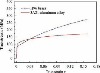
Fig. 2 True stress-strain curves of H96 brass DRRT and 3A21 aluminum alloy ridge groove filler.

Table 1 Main mechanical properties of H96 brass DRRT and 3A21 aluminum alloy ridge groove filler.
The surface to surface contact model is used to define the contact between the non-deformable rigid dies, including the bending die, pressure die, mandrel and so on, and the tube which is selected as slave face. The height and width of filler are the same with those of ridge groove, which means that the clearance between filler and tube is set to be 0 mm in simulation.So the contact between the filler and tube is defined by two contact models of surface to surface contact and general contact, and their simulation results are shown in Fig. 3. It can be seen that, when using the surface to surface contact model, the penetration phenomenon occurs between the filler and tube, as shown in Fig. 3(a). But there is non-penetration found in Fig.3(b)when the general contact model is used.This may be because in the surface to surface contact model, the master face of the contact pair can penetrate to the slave face,but as two deformable faces, the tube and filler should not be penetrated each other. So the general contact model is chosen to define the contact between the filler and tube.
2.3. Establishment of the FEM for H-typed bending process
The three-dimensional FEM for the actual entire H-typed bending process of H96 DRRT with fillers are composed of four sub-models, which are the H-typed bending model, the rigid mandrel retracting model, the first springback model after unloading the rigid dies and the second springback model after removing the fillers.
(1) The H-typed bending model
Except for the definition of the above material models and contact models,for improving the computational accuracy and efficiency of the models, based on the geometric model shown in Fig.4(a),the element type of the tube and ridge groove filler are defined as a deformable 8-node hexagonal reduced integral solid element(C3D8R)with five integration points,meanwhile the rigid dies are defined as the bilinear quadrilateral rigid shell element with four nodes(R3D4).The mesh sizes of tube,filler and mandrel are all 1 mm×1 mm,and that of other rigid dies are all 3 mm×3 mm. The angular velocity of bending die is 0.5 rad·s-1. After solving the above key technologies, based on the platform of ABAQUS/Explicit, the H-typed bending model of H96 brass DRRT with 3A21 aluminum alloy ridge groove fillers is established, as illustrated in Fig. 4(b).
(2) The rigid mandrel retracting model
When the bending stage is completed, the rigid mandrel retracting begins at the velocity of 60 mm·s-1, and the time of this stage is one second.The rigid mandrel retracting model is shown in Fig. 4(c).
(3) The first springback model
Because the fillers are still in the ridge grooves after unloading the rigid dies,so the first springback model after unloading all the rigid dies,that is,the synchronous springback model of the double-ridged rectangular bent tube and deformed fillers.

Fig. 3 Comparisons of different contact models for tube and filler.
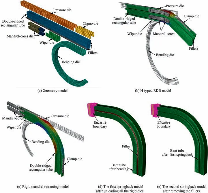
Fig. 4 Models of the entire H-typed RDB of H96 brass DRRT with ridge groove fillers.
The springback is the release process of stress and strain of the double-ridged rectangular bent tube and fillers after bending process. The information such as stress and strain of the double-ridged rectangular bent tube and fillers in the result file,which is calculated by the previous step bending model, is introduced into the first springback model and defined as the initial field. The contact model of the tube and fillers is the same as in the bending model. In order to avoid the rigid displacement of bent tube and fillers during the springback, it is needed to impose sufficient constraints on the formed tube and fillers. A encastre boundary is applied to end position of the DRRT where is not deformed during the bending process,so that the stress and strain of the double-ridged rectangular bent tube and fillers can be released freely.Based on the above analysis, the first springback model after unloading all the rigid dies is established and shown in Fig. 4(d).
(4) The second springback model
The second springback model,as shown in Fig.4(e),is built to simulate the final springback of tube after the fillers are removed, whose establishing method is similar to that of the first springback model.
2.4. Experimental verification of the finite element models
2.4.1.Description of the cross-sectional deformation of tube and filler
In order to quantitatively analyze the cross-sectional deformation of DRRT and filler in H-typed bending,the description of deformation is given as follows:δHiand δhiare used to indicate the height deformation of tube and ridge groove; δBiand δbiare used to indicate the width deformation of tube and spacing deformation of ridge grooves; δh′iand δb′iare used to indicate the cross-sectional height and width deformation of filler.These deformations can be calculated by Eqs. (3)-(8),respectively.
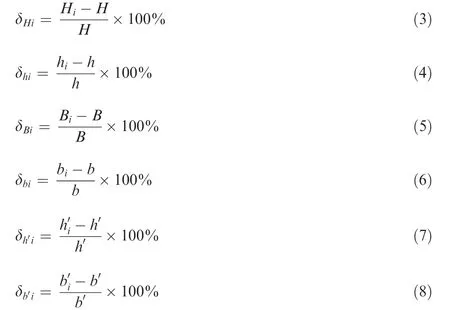
where as shown in Fig. 5(a), the schematic diagram of certain cross section of DRRT before deformation, H=18.29 mm and h=4.39 mm are the original height of tube and ridge groove;B=8.15 mm and b=2.57 mm are the original width of tube and spacing of ridge grooves; as shown in Fig. 1(b),h′=1.85 mm and b′=2.75 mm are the original height and width of filler. Hi(i=1(1′)-10(10′)), hi(i=11(11′)-14(14′),15(15′)-18(18′)), Bi(i=19(19′)-26(26′), 32(32′)-39(39′)), bi(i=27(27′)-31(31′)), hi′(i=41(41′)-44(44′)), and bi′(i=41(44),40(45),41′(44′))are those corresponding sizes at a certain node i (as shown in Fig. 5(b) and (c)) after deformation.
According to the above expressions, the positive value of a deformation indicates that the size increases after deformation,and relatively the negative value indicates the decrease. For negative value, the greater the absolute value, the more severe the deformation.
2.4.2. Experimental validation
In order to ensure the credibility of the next research results,it is necessary to verify the reliability of the above established models by comparing result error between the experiment and simulation. The DRRT with ridge groove fillers and experiment process of H-typed RDB are shown in Fig. 6.The simulation conditions are consistent with the experimental ones, as shown in Table 2.
Based on the experimental and simulation conditions shown in Table 2, the comparisons between the experimental and simulation results are carried out. The experiment is carried out with three specimens, the profiles of these experimental specimens are basically consistent. So one representative bent specimen is chosen to be shown in Fig. 7(a) and (b). As shown in Fig.7(a)and(b)ignoring the smaller fillet of the real tube,the profiles of the bent tube after the fillers were removed and the deformation of a certain cross section of the final bent tube obtained from the simulation are basically coincide well with those from the experiment. Furthermore, based on the Eqs. (3) and (6), the distribution of δHof node 5(5′) and δbof node 27(27′)in characteristic cross sections along the bending direction from the simulation bent tube and three experimental specimens are obtained and shown in Fig. 7(c) and(d). It can be seen that the results of these three experimental specimens are similar and their distribution laws are basically the same, so the average of these experimental results can be used to compare with the simulation results. Then it can also be obtained that the distribution of deformations along the bending direction from the simulation results is in agreement with that from the average experimental results,the maximum errors between average experimental results and simulation ones of these two deformation are about 8.4% and 9.8%,respectively, and the average errors of them are both about 4.8%. The offset may be produced by many reasons, such as the error in measuring the experimental bent tube, the clearance between the tube and bending dies was not accurate to 0 because of the dimension tolerance allowed in machining the dies and so on. These errors of no more than 10% are acceptable,which means that the simulation and experimental results are highly consistent. Therefore, three-dimensional FEM including the H-typed RDB and mandrel retracting models of DRRT with 3A21 aluminum alloy ridge groove fillers and two springback models are reliable,and the next study can be conducted on this basis.
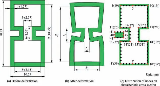
Fig. 5 Schematic diagram of DRRT before and after deformation.
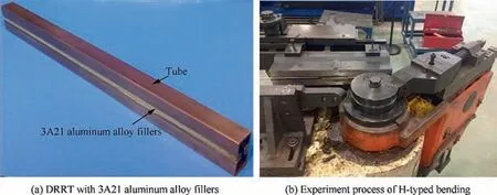
Fig. 6 Experiment process of H-typed rotary draw bending of DRRT with ridge groove fillers.
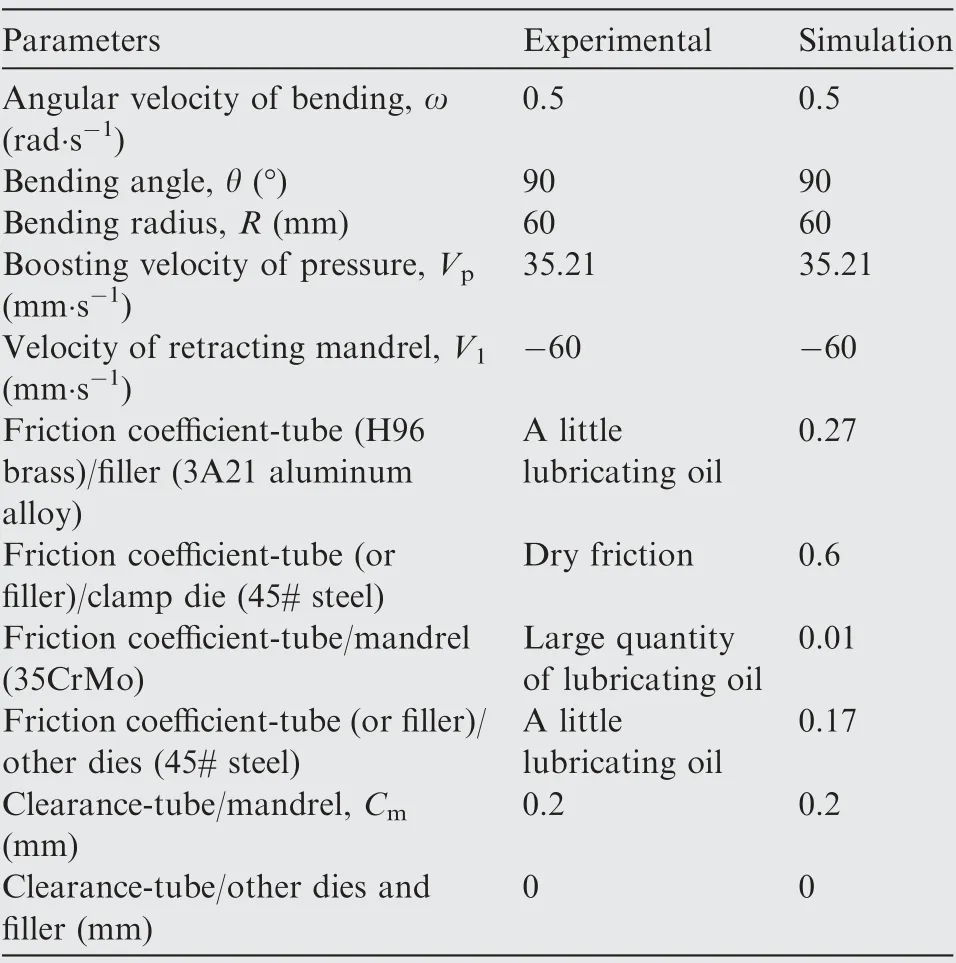
Table 2 Experimental and simulation conditions.
3. Cross-sectional deformation of DRRT and filler in the entire H-typed RDB
3.1. Height deformation of tube
In the H-typed bending process of DRRT,the outer flange and inner flange are depressed and deformed under the action of tangential tensile and compressive stress respectively. The different depressions of inner and outer flanges cause the height of tube to change, that is, the height deformation of tube δHioccurs. Based on the established bending, mandrel retracting and twice-springback models, different depressions of inner and outer flanges of section S1 in mandrel-support zone and section S6 in non-mandrel-support zone (as shown in Fig. 8)at each stage of the entire H-typed forming process have been obtained and shown in Fig.9(a)and(b).And according to Eq.(3),δHiof section S1 and S6 are calculated and shown in Fig.9(c) and (d).
It can be seen that the depressions of inner and outer flanges and height deformation of tube are both symmetrically distributed along the width direction.At any stage of the entire forming process,the maximum deformation is located at node 5(5′)in the middle of flanges.After bending stage,the depression of inner flange of sections S1 and S6 are almost the same,and due to the support of rigid mandrel, the depression of outer flange of section S1 is significantly smaller than that of section S6, which makes δHiof section S1 smaller than that of section S6. After the mandrel retracting stage, because the support of mandrel to section S1 is missing, only the outer flange depression of section S1 increases.So that δHiof section S1 increases, while that of section S6 remains basically unchanged at this stage.It is indicated that the use and retraction of the rigid mandrel affect the height deformation of tube in mandrel-support zone more significantly than that in nonmandrel-support zone, and the influence on the depression of outer flange is greater than that of inner flange.
After the first springback, the outer flanges of sections S1 and S6 both move up, the inner flanges move down, which means that the depression of outer and inner flanges of these two sections decrease and tend to be gentle. That is, δHiof these sections are both reduced at this stage. After the second springback, the depression of outer flange of section S1 keeps substantially unchanged, but the depression of outer flange of section S6 continues to become smaller. The depressions of inner flange of these two sections both become larger slightly.After calculating,δHiof these sections are slightly increased at this stage.
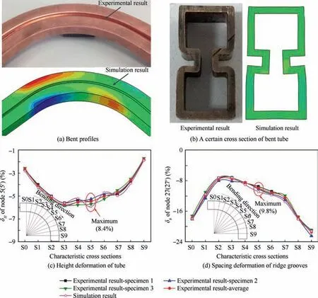
Fig. 7 Simulation and experimental results after the fillers were removed.
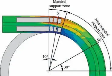
Fig. 8 Distribution of characteristic cross sections.
Overall,the change of depression of outer flange of section S1 during the mandrel retracting stage is larger than that in the twice-springback stage.The influence of first springback on the inner flange depression of section S1 and outer and inner flanges depressions of section S6 are significantly greater than the second springback,and the mandrel retracting stage can be ignored. This is because only the stress in mandrel-support zone is unloaded during the mandrel retracting stage, while the stress of whole bent tube is released during the first springback stage, then a slight springback of deformation is only caused by the removal of the fillers in the second springback stage.
Therefore, for the height deformation of tube in mandrelsupport zone, the mandrel retracting and first springback stages should be emphasized and considered simultaneously.For the height deformation of tube in non-mandrel-support zone, focusing on the first springback stage is enough.
3.2. Height deformation of ridge groove
The height deformation of ridge groove δhiis caused by the change of the position of inner and outer walls of ridge groove.Based on the established models, the position of inner and outer walls of ridge groove of section S1 and S6 in the entire H-typed forming process is obtained and shown in Fig. 10(a)and (b). And according to Eq. (4), δhiof section S1 and S6 are calculated and shown in Fig. 10(c) and (d). It can be seen that,the deformation of the left and right ridge grooves is symmetrical, so only analyzing one side is enough. On these two sections, the inner and outer walls of ridge groove basically both move upward, the displacement of inner wall is larger than that of outer wall, which makes the height of the ridge groove reduced. The displacement and δhiof node 11 (11′)located at the intersection of side wall and ridge groove are the largest at any stage of the entire forming process.
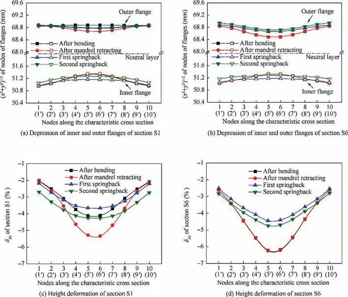
Fig. 9 Depression of inner and outer flanges, height deformation of section S1 and S6 after bending, mandrel retracting and twicespringback process.
After bending, although the displacement of inner and outer walls of ridge groove of section S1 is slightly larger than that of section S6,because of the supporting effect of fillers on ridge grooves, δhiof these sections are almost the same and both very small, the maximum δhiis less than 1.5%. After the mandrel retracting, the position of outer and inner walls of ridge groove of section S6 substantially unchanges. The outer and inner walls of ridge groove on section S1 move down slightly to the same position as the section S6, but the change of δhiis small and negligible.This shows that due to the introducing of filler,the influence of the use and retraction of mandrel on the height deformation of ridge groove in the entire bent tube is small and even not needed to be considered.
Then during the first springback, the inner and outer walls of ridge groove on section S1 move downward slightly, while those on section S6 move up slightly, eventually reducing δhiof the two sections. But because the fillers are not removed at this stage,they still have a certain support effect to the ridge groove, δhiat this stage has little difference with that after mandrel retracting. After the second springback, because the fillers are removed, whose support function to the ridge grooves does not exist, the inner wall of ridge groove on these two sections relatively move upward relatively larger, so that the height deformation of ridge groove increases.
Overall, whether in the mandrel-support zone or the nonmandrel-support zone,only the second springback has a significant effect to increase the height deformation of ridge groove,other stages can be ignored.
3.3. Width deformation of tube
Since the deformations of the two side walls of bent tube are symmetrical,therefore,unlike the deformation in height direction studied above, only analyzing the width deformation of tube directly is enough.
Based on the established models,the width deformation δBiof section S1 and S6 in the entire H-typed forming process are obtained and shown in Fig.11(a)and(b).It can be found that after bending, under the support of mandrel, δBiof section S1 is much smaller than that of section S6.Especially in the outer area of neutral layer, where the deformation is bigger, δBiof each node on section S1 is relatively gentle. But on section S6, the closer to the ridge groove, the larger the δBi, and at the intersection of side wall and ridge groove, that is δBion node 26(26′) is the largest. After the mandrel retracting stage,δBiof section S6 is not changed,but δBiof section S1 is significantly increased,due to the support function of mandrel does not exist, and the distribution law of δBiis the same as that of section S6. At this stage, δBiof section S1 is even higher than that of section S6.It is shown that,except for the height deformation of tube,the use and retraction of the rigid mandrel also affect the width deformation of tube in mandrel-support zone more significantly,and the influence on the deformation of side wall in outer area of neutral layer is greater than that in inner area.
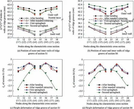
Fig. 10 Position of outer and inner walls of ridge groove, height deformation of ridge groove of section S1 and S6 after bending,mandrel retracting and twice-springback process.
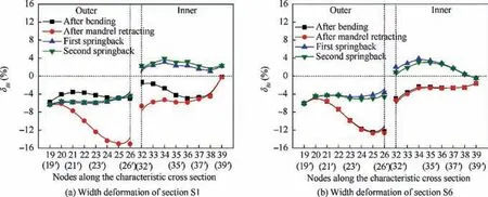
Fig. 11 Width deformation of section S1 and S6 after bending, mandrel retracting and twice-springback process.
After the first springback,in the outer area of neutral layer,δBiof these two sections are both reduced and δBiof each node is basically the same.But in the inner area of neutral layer,δBiis changed from negative to positive,which makes a‘‘bulk belly” phenomenon appear. After the second springback, δBiin the outer area of neutral layer of section S1 is slightly decreased, while in the inner area is slightly increased. The change of δBion section S6 is exactly contrary to that on section S1.However,it can also be seen that the changes of δBion these two sections are both very small and even negligible,that is,there is no need to study δBiduring second springback stage emphatically.
Overall, as same as the height deformation of tube, for the width deformation of tube in mandrel-support zone, the mandrel retracting and first springback stages should both be emphasized and considered. For the non-mandrel-support zone, focusing on the first springback stage is enough.
3.4. Spacing deformation of ridge grooves
Like the width deformation of tube,only studying the spacing deformation of ridge grooves δbiof sections S1 and S6 in the entire H-typed forming process, which are shown in Fig. 12.It can be obtained that at any stage of the entire forming process,the bottoms of ridge grooves move to the middle of tube,so that the spacing of ridge grooves is decreased. Along the height direction, from node 27(27′) to 31(31′), δbiis gradually decreased,the maximum δbioccurs at the node 27(27′),so that the bottoms of the ridge grooves have a trapezoidal shape.
Similar to the width deformation of tube,after bending,δbiof each node on section S1 is far smaller and more gentle than that of section S6. After mandrel retracting, δbiof section S6 can be considered to remain unchanged,δbiof section S1 is significantly increased to a greater value.
After the first springback,δbiof these two sections are both notably reduced, and even the expansion deformation can be found in the inner area of neutral layer. After the second springback,the bottoms of ridge grooves of these two sections move toward the middle, which makes the spacing deformation δbiincreased. The change of δbion section S6 is slightly larger than that on section S1. However, it can also be seen that the variation of δbiduring the first springback stage is much greater than that during the second springback.
Overall,due to the bottoms of ridge grooves and side walls of tube may move together in the entire H-typed forming process, the law of change of the width deformation of tube and spacing deformation of ridge grooves between each stage is almost identical.Therefore,as the same as the width deformation of tube, for the spacing deformation of ridge grooves in mandrel-support zone,the mandrel retracting and first springback stages should be emphasized and considered.In the nonmandrel-support zone,focusing on the first springback stage is enough.
3.5. Cross-sectional deformation of filler
During the bending process, the fillers are bent and deformed together with the tube, while in the first springback, they may also have springback synchronously. Therefore, it is necessary to obtain the cross-sectional deformation of bent filler to study whether the springback of filler has an effect on the crosssectional deformation of bent tube during the first springback.At the same time, for comparative research, without the bent tube, the springback of bent filler itself after the mandrel retracting process is also added.
According to the previous analysis, it is found that the height deformation of ridge groove in the mandrel-support zone and non-mandrel-support zone is similar, it can be thought that the deformation of different positions of bent filler is almost the same.Therefore,the cross section of filler corresponding to section S6 of tube is selected for research.
Fig.13 shows the height and width deformation of filler on the chosen cross section at bending, mandrel retracting and springback process. It can be drawn that after the bending stage, the height deformation of filler is larger than the width deformation, and the δh’iat node 44(44′) is the largest. This is because the filler is only squeezed by the ridge groove in the height direction, so the width deformation of filler can be ignored. The deformation of filler does not change after mandrel retracting, so the mandrel retracting process has no effect on the deformation of filler.It can also be seen from Fig.13(a)that if without the bent tube, only the bent filler itself has springback, the height deformation of filler will decrease, but the change of height deformation in this condition is slightly larger than that in the first springback.This shows that during the first springback process, the springback of filler and ridge groove is interacted, there is still a small interaction between the ridge groove and filler at this time. So that the results are obtained and shown in Fig.10(d)and Fig.13(a):after the first springback, the height deformation of ridge groove and filler are slightly reduced.
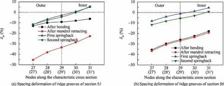
Fig. 12 Spacing deformation of ridge grooves of section S1 and S6 after bending, mandrel retracting and twice-springback process.
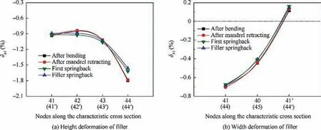
Fig. 13 Height and width deformation of filler at bending, mandrel retracting and first springback process.
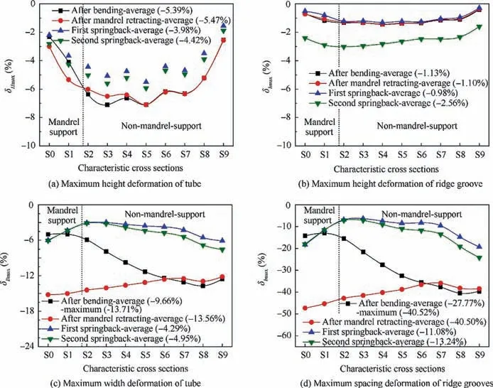
Fig.14 Distribution of maximum cross-sectional deformation of tube along the bending direction after bending,mandrel retracting and twice-springback process.
Overall, the distribution law of the height deformation of filler and ridge groove are basically the same at each stage.The deformation of filler is very small, the maximum height deformation and width deformation are only 1.8% and 0.8%,respectively.The springback of deformation can also be negligible. Therefore, the deformation of filler is no longer to be analyzed in the following research.It can also be considered that 3A21 aluminum alloy is a good choice as the ridge groove filler.
4. Distribution of maximum cross-sectional deformation of DRRT in the entire H-typed RDB
In order to study the cross-sectional deformation of the whole bent tube more comprehensively,choosing the nodes obtained above where the maximum deformations of δHi,δhi,δBiand δbiin the cross section occur,δHmax,δhmax,δBmaxand δbmaxrepresent the corresponding maximum deformations of each characteristic cross section. The distribution of δHmax, δhmax,δBmaxand δbmaxalong the bending direction in the entire Htyped forming process are shown in Fig. 14.
It can be known that, due to the use of filler, δhmaxafter bending and mandrel retracting process is same and evenly distributed along the bending direction, the difference between each characteristic cross section is very small.However,δHmax,δBmax, and δbmaxin mandrel-support zone are significantly smaller than those in the non-mandrel-support zone after bending,especially the greater deformations in the width direction,that is,δBmaxand δbmaxboth gradually increase along the bending direction.After mandrel retracting,the distribution of δHmax, δBmaxand δbmaxalong the bending direction tend to be uniform. δHmaxin mandrel-support zone increases, that in the sections S2-S5 decreases and that in other sections remains unchanged. Not only in the mandrel-support zone, δBmaxand δbmaxin sections S0-S6 increase significantly, and that in other sections are slightly decreases.
Compared with the cross-sectional deformation after mandrel retracting, during the first springback, δhmaxis still approximately constant, but other deformations are all reduced. Especially the deformations in the width direction,the average of δBmaxis changed from 13.56% to 4.29%, while the average of δbmaxis changed from 40.50%to 11.08%,these deformation are almost reduced by 2/3. After the second springback, δHmax, δBmaxand δbmaxincrease slightly, but the changes of these deformations during the secong springback are much smaller than that during the first springback. Due to the fillers are removed, δhmaxbegins to be changed and increased at the second springback stage,but the change of δhmaxis also very small, which is about 1.58%. This is because most stress of bent tube is released during the first springback stage, but only a small amount of remaining stress is required to be released during the second springback stage.
The same results as the analysis of Section 3 can also be obtained from the above research that, for the height and width deformation of tube and spacing deformation of ridge groove, the retraction of mandrel has an obvious effect on these deformations in the mandrel-support zone,which makes the distribution of these deformations more uniform along the bending direction, especially the deformations in the width direction; the first springback makes them reduced significantly, but the second springback makes them increased slightly,the effect of the first springback on these deformations is significantly greater than the second springback. For the height deformation of ridge groove, only the second springback can make it increased slightly, the average of δhmaxafter the second springback is only 2.56%,which is still far less than δbmax.
5. Conclusions
(1) The finite element models including the H-typed rotary draw bending, mandrel retracting and twice-springback stages of double-ridged rectangular tube with 3A21 aluminum alloy ridge groove fillers have been established,and validated by the experiment.
(2) For the height and width deformation of tube and spacing deformation of ridge groove, the retraction of mandrel can make the distribution of these deformations more uniform along the bending direction; the first springback makes them reduced significantly, but the second springback only makes them increased slightly.For the smaller height deformation of ridge groove,only the second springback can make it increased slightly.
(3) During the first springback process, the springback of cross section of filler and ridge groove is interacted in the height direction, so that the height deformation of ridge groove and filler are slightly reduced.The distribution law of the height deformation of filler and ridge groove are basically the same at each stage.
(4) In the subsequent research of controlling the crosssectional deformation in the entire H-typed forming process with fillers, the smaller height deformation of ridge groove and filler can be neglected.The bending,mandrel retracting and first springback stages, that significantly affect the cross-sectional deformation,should be emphasized and considered at the same time. The second springback stage with less change of cross-sectional deformation can be ignored.
Acknowledgements
The authors would like to thank the Science, Technology and Innovation Commission of Shenzhen Municipality of China (Nos. JCYJ20170306160003433 and JCYJ2018030617 1058717) and 111 Project of China (No. B08040) for the support given to this research.
 CHINESE JOURNAL OF AERONAUTICS2020年6期
- CHINESE JOURNAL OF AERONAUTICS的其它文章
- A novel variable structure multi-model approach based on error-ambiguity decomposition
- Multi-block SSD based on small object detection for UAV railway scene surveillance
- A new online modelling method for aircraft engine state space model
- Cross-sectional deformation of H96 brass double-ridged rectangular tube in rotary draw bending process with diあerent yield criteria
- Application of a PCA-DBN-based surrogate model to robust aerodynamic design optimization
- Numerical exploration on the thermal invasion characteristics of two typical gap-cavity structures subjected to hypersonic airflow
