Inverted decoupling and LMI-based controller design for a turboprop engine with actuator dynamics
Huairong CHEN, Xi WANG,*, Haonan WANG, Nannan GU,Meiyin ZHU, Shubo YANG
a School of Energy and Power Engineering, Beihang University, Beijing 100083, China
b Collaborative Innovation Center for Advanced Aero-Engine, Beijing 100083, China
KEYWORDS Actuator dynamics;Inverted decoupling;Linear Matrix Inequality(LMI);Static output feedback;Turboprop engines
Abstract The main objective of the turboprop engine control system is to ensure propeller absorbed power at a constant propeller speed by controlling fuel flow and blade angle. Since each input variable affects the selected output variables,there exist strong interactions between different control loops of a Two-Spool TurboProp Engine(TSTPE).Inverted decoupling is used to decouple the interactions and decompose the TSTPE into two independent single-input single-output systems. The multi-variable PI controller and two single-variable PI controllers are designed for the TSTPE with actuator dynamics based on Linear Matrix Inequality (LMI), respectively, which is derived from static output feedback and pole placement condition. The step responses show that due to the difference in the response times of the selected output variables, it is difficult to design an appropriate multi-variable PI controller. The designed single-variable PI controllers are tested on the TSTPE integrated model to illustrate the effectiveness of the proposed method, that is,the interactions are first decoupled and then the controllers are designed, and the resulting simulated responses show that compared with the controller designed without actuator dynamics, the gas-generator shaft speed and power turbine shaft speed can better track their respective commands under the action of the controller designed with actuator dynamics.
1. Introduction
Compared with turbojet and turbofan engines, early turboprop engines have such problems as high noise and low flight speed. Encouragingly, the concern for the environment and determination to overcome these problems have made it possible for new turboprop aircrafts to fly at high altitude and high subsonic speed. For example, the cruise speed of A400M aircraft equipped with TP400-D6 engine, which is the most powerful western three-spool turboprop engine,1is 781 km/h at 9450 m,that is,the Mach number is about 0.72,indicating that the performance of modern turboprop aircrafts can be comparable to turbofan aircrafts. Thanks to low specific fuel consumption, large power-weight ratio, large takeoff thrust of turboprop engines, turboprop engines are widely used in military transport aircrafts, regional aircrafts, air early warning aircrafts and so on.Turboprop engines are still under intensive investigation today, for example GE is developing Catalyst Advanced TurboProp (ATP) engine to compete with PT6A-60 engines.2
With the development of turboprop engines, the demand on the control system has also grown and the control system of a turboprop engine has developed from hydraulic mechanical to dual channel Full Authority Digital Electronic Control(FADEC)with engine health management system.3For example, TP400-D6 engine uses a complex dual channel FADEC system, which integrates propeller control system with engine control system.1Similar to TP400-D6 engine, the Catalyst ATP engine uses a Full Authority Digital Engine and Propeller Control (FADEPC) system to implement a single-lever turboprop engine control system instead of hydraulic mechanical multi-lever control system, which greatly reduces the pilot’s workload and maximizes engine performance without exceeding the constraints.However,it has always been a challenge to design a control system for a turboprop engine, which has caused great interests among researchers in the field of aircraft engines.In 1968,Keck et al.developed a hydraulic mechanical adaptive fuel control system for a turboprop engine to solve two problems simultaneously, which were fuel contamination and the required power-trim adjustment for fuel-supply variation in type and quality.4Badger et al.introduced the function and components of the PT6-68 Power Management System(PMS) and summarized the features and benefits of the PMS.5Hosking et al. described the evolution of the PW100 engine,and especially they presented the changes of the control loop of the PW100 engine, i.e., early closed-loop control was based on the rate of change of gas-generator shaft speed,lately on torque,and ultimately on power.6Povazˇan et al.introduced an Engine Thrust Management System (ETMS) to give the control commands and presented the gas-generator shaft speed control loop and propeller speed control loop of a turboprop engine.7LeBrun et al.analyzed the interactions between different control loops of simplified linear discrete model obtained by identifying the simulation data of a turboprop engine and tuned the PI controllers based on the Internal Model Controller (IMC) method.8,9
From the previous work,it can be seen that the main objective of the turboprop engine control system is to ensure propeller absorbed power at a constant propeller speed by controlling fuel flow and blade angle.Therefore,from the perspective of control, a turboprop engine is a typical multivariable system. The most straightforward way to design a control system for a turboprop engine is to design a multivariable controller. However, it is difficult to design a proper multi-variable controller that meets the design specifications simultaneously. Due to strong interactions between different control loops of a turboprop engine, it is difficult to design a controller for each control loop independently. To reduce these interactions, some researchers focused on multi-loop control because of its simplicity in implementation.10Besides,decoupling control drew many researchers’ interests, and its strategy is to disentangle the interactions between different input-output channels and decompose a multi-variable system into a number of independent Single-Input Single-Output(SISO) system, which was used for many industrial processes.11-14Generally, the conventional decoupling methods mainly include simplified, ideal and inverted decoupling.15Simplified decoupling has a decoupler that is easy to implement, but the resulting transfer matrix is intricate and controller tuning can be difficult. Ideal decoupling facilitates controller design, but the decoupling matrix is complicated and difficult to realize. Inverted decoupling avoids the realization problem of ideal decoupling while keeps the main advantages of simplified and ideal decoupling at the same time.
PI/PID controllers are still the preferred control methods for many industrial systems because of their structural simplicity and good robustness.However,there exists such a problem that the PI controller is blindly tuned based on the test results in engineering,which reduces the robustness of the control system. Since the closed-loop pole can reflect the stability and dynamic performance of the control system, pole placement has become one of the most important methods to design a suitable dynamic response for linear control systems.16,17Moreover, many problems involving synthesizing dynamic control can be transformed into Static Output Feedback(SOF) control problems, especially PI/PID control.18-22Because an engine real actuator has the dynamics,position saturation limit and rate saturation limit, it should be considered the impacts of an actuator when designing controllers for an aircraft engine. The position saturation limit and rate saturation limit of an actuator have been discussed in the Refs.23,24.The Ref.22show that the dynamic responses of the fuel flow and blade angle of the Two-Spool TurboProp Engine(TSTPE)integrated model under the action of the controller designed without actuator dynamics have a small oscillation.Therefore,this paper aims to present the new controller design procedure,to analyze the influences of actuator dynamics on the closedloop, and to compare to the controllers designed in the Ref.22on the TSTPE simulation platform.
2. TSTPE control loops and normalized linear model
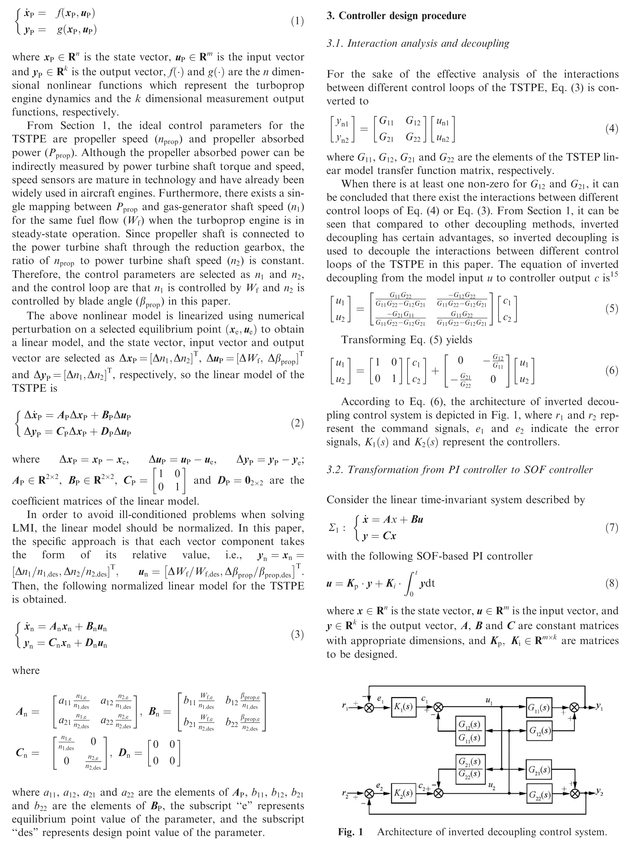
In this paper, the TSTPE is used to illustrate the effectiveness of the method of designing controllers based on inverted decoupling and Linear Matrix Inequality (LMI) for a class of turboprop engines. The typical configurations for the TSTPE include a variable pitch propeller,a reduction gearbox,an intake, a compressor, a burner, a gas-generator turbine, a power turbine, a nozzle, so it can be regarded as consisting of two parts: turbojet engine and propeller. With the help of NASA’s Toolbox for the Modeling and Analysis of Thermodynamic Systems (T-MATS),25the component-based model of turbojet engine is built. The propeller model is built based on propeller modeling algorithm proposed by the Refs.26,27.The power turbine shaft dynamics equation is derived from the power balance between the power turbine shaft output power and the propeller absorbed power. Thus, the component-based integrated model of the TSTPE is built.For ease of analyses, it is assumed that the TSTPE integrated model can be described as remain the same with the flight conditions and βpropunchanged. From Eq. (33), as npropincreases, so does Pprop.Meanwhile, it can be found that the response time of n1is about 10 s,and that of n2is about 50 s.The difference between the two is about 5 times.
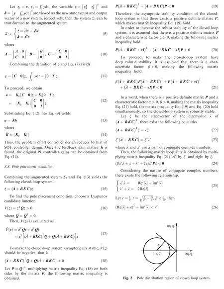
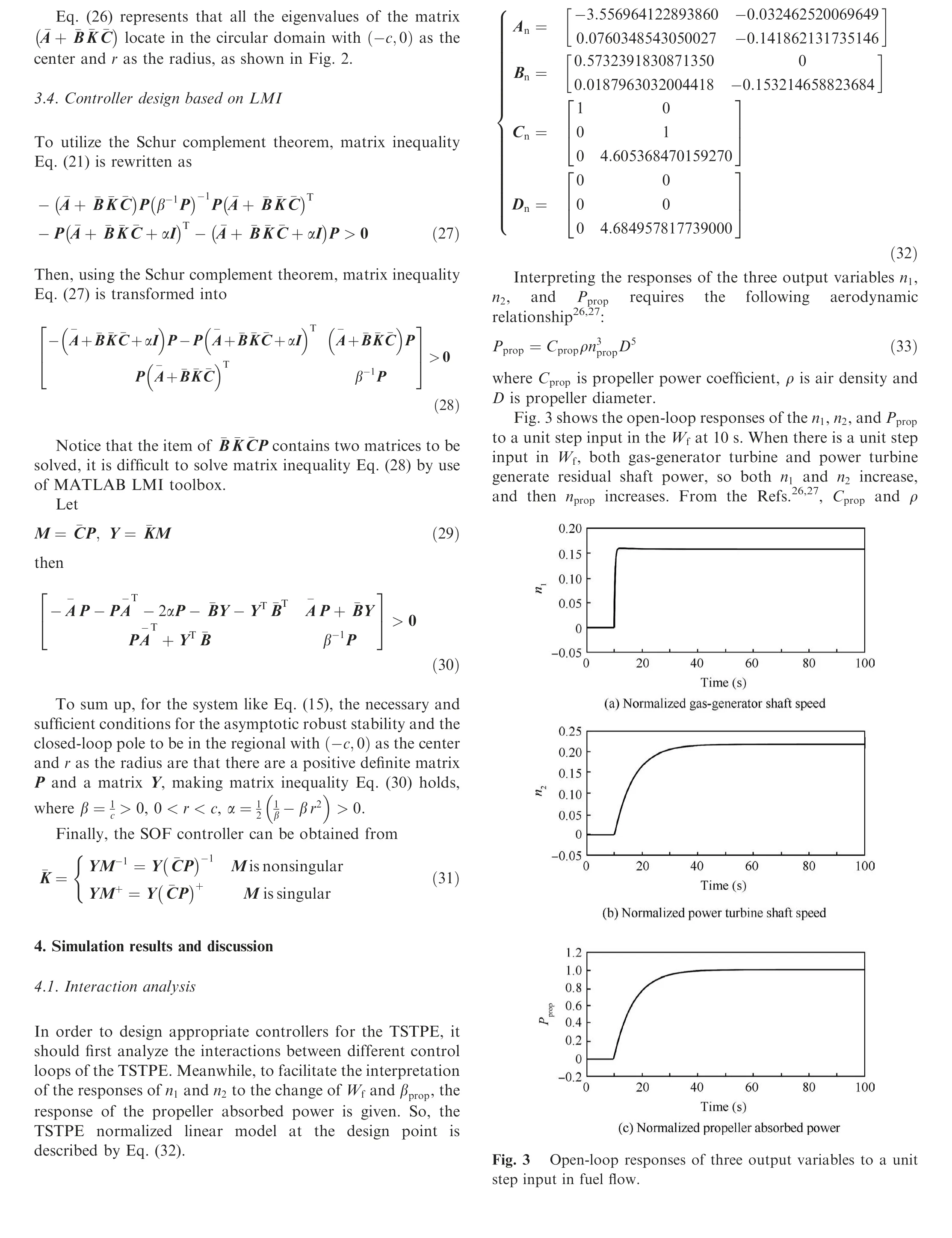
The step responses of the n1,n2,and Ppropto the βpropinput variable at 10 s are shown in Fig.4.When βprophas a unit step and other conditions remain unchanged,Cpropbecomes instantaneously large from the Refs.26,27. From Eq. (33), propeller absorbed power increases instantaneously, as shown in Fig.4(c), causing the shaft power produced by power turbine to be less than propeller absorbed power, resulting in the deceleration of n2. Therefore, as time goes by, n2decreases, as shown in Fig.4(b),and npropalso decreases.On the other hand,when flight conditions and βpropare changeless, Cpropand ρ remain constant. From Eq. (33), propeller absorbed power becomes small with the reduction in nprop, as shown in Fig.4(c). The reduction in n2reduces the shaft power generated by the power turbine, so the temperature of the power turbine inlet or the gas-generator turbine outlet gas flow decreases. Furthermore,since the temperature of the gas-generator turbine inlet gas flow remains the same, the shaft power generated by the gasgenerator turbine is increased, causing the shaft power produced by the gas-generator turbine to be greater than the shaft power consumed by the compressor, leading to the acceleration of n1. Therefore, as time passes, n1increases, as shown in Fig.4(a). The response time of n1, n2and Ppropis almost 50 s.But,the response time of n1to the change of Wfis different to that of n1to the change of βprop.
In summary, there exist strong interactions between the n1control loop and n2control loop of the TSTPE and the response times of n1and n2to the change of each input variable are very different,which creates great difficulties for controller design.limited space, the actuator dynamics are directly considered for the multi-variable PI controller design.
In engineering, the dynamics of an engine actuator can be modeled by a first-order lag as28

where ucmdis the actuator command calculated by the controller, uactis the actuator output and τ is the nominal time constant of an engine actuator.
Since there is no specific time constant of the TSTPE actuators,assuming that the nominal time constant of the fuel flow actuator is 0.02, and the nominal time constant of the blade angle actuator is 0.05.
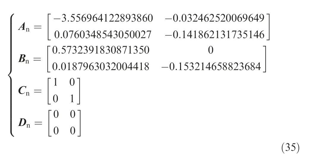
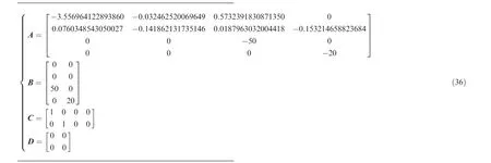
The TSTPE normalized linear model at the design point is described by Eq. (35). In order to consider the actuator dynamics,the specific way is to augment the fuel flow actuator dynamics and the blade angle actuator dynamics into Eq. (35)to form a new system,as presented in Eq.(36),which is like the system described by Eq. (7). Then the multi-variable PI controller is designed according to Sections 3.2-3.4.
4.2. Multi-variable PI controller design via LMI
According to the above analysis, the most direct method is to design a multi-variable PI controller for the TSTPE. Due to
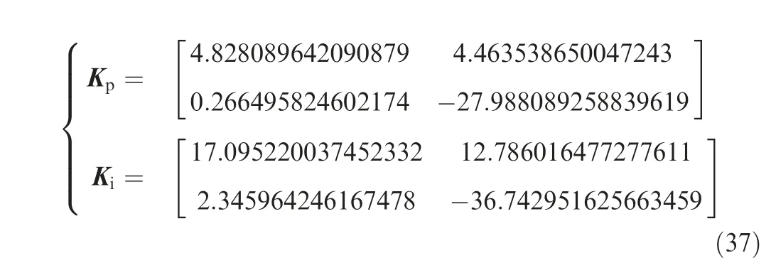
Setting c, r to 4 and 2, respectively, recorded as (4,2),matrix inequality Eq. (30) is solved by using MATLAB LMI toolbox, and then the multi-variable PI controller gains are
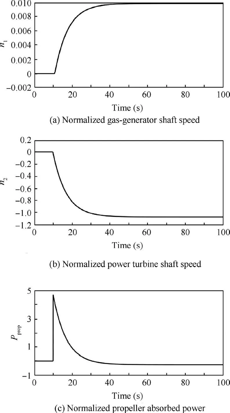
Fig. 4 Open-loop responses of three output variables to a unit step input in blade angle.
To compare the effects of different (c ,r) on the step responses of n1and n2,many groups (c ,r)are chosen to obtain different multi-variable PI controllers, and the closed-loop responses are shown in Fig. 5, where Wfactand βpropactrepresent the fuel flow actuator output and blade angle actuator output, respectively. Under the action of designed multivariable PI controller, it is difficult for the responses of the TSPTE normalized output variables to satisfy their optimal performance indices simultaneously, which is mainly because there exists a great difference in the response times of n1and n2to the change of Wf.
4.3. Single-variable PI controller design via inverted decoupling and LMI
4.3.1. Inverted decoupling verification
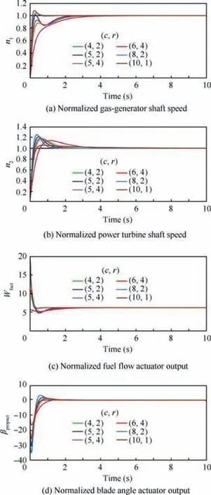
Fig. 5 Unit step responses of output and input variables with multi-variable PI controller, fuel flow actuator and blade angle actuator.
Since it is difficult to design a proper multi-variable PI controller for the TSTPE, the decoupling control strategy is extended to design a single-variable PI controller for each control loop of the TSTPE separately. Before designing a singlevariable PI controller, it should be verified whether inverted decoupling could effectively decouple the interactions between different control loops of the TSTPE.
The TSTPE normalized linear model at the design point described by Eq. (35) is selected to illustrate the effectiveness of applying inverted decoupling to the TSTPE, and its decoupling effects are shown in Figs.6 and 7.Fig.6(b)presents that Wfhas little influences on n2and Fig.7(a)shows that βprophas little effects on n1, which demonstrate that the interactions between the n1control loop and n2control loop are decoupled by using inverted decoupling.
4.3.2. Single-variable PI controller design
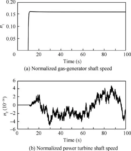
Fig. 6 Open-loop responses of output variables with inverted decoupling to a unit step input in fuel flow.
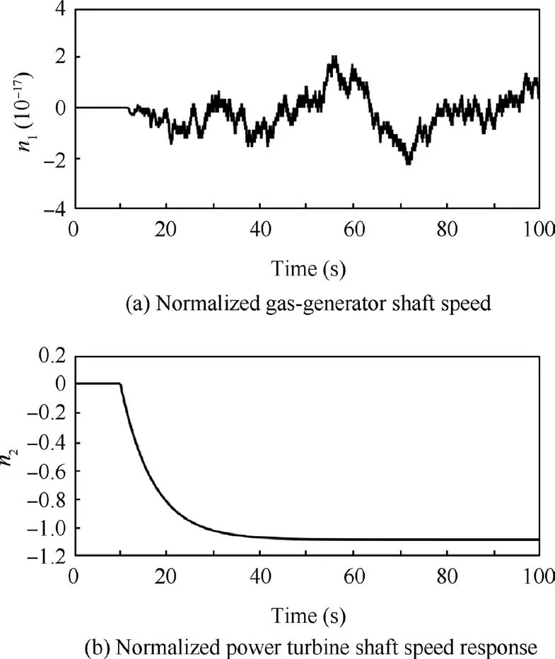
Fig. 7 Open-loop responses of output variables with inverted decoupling to a unit step input in blade angle.
Comparing Fig.6(a) with Fig.3(a) and Fig.7(b) with Fig.4(b), it can be found that using inverted decoupling hardly changes the dynamics of the original system. Thus, the singlevariable PI controller can be designed based on the original normalized linear model.
Firstly, the normalized linear model from Wfto n1described by Eq. (38) is considered. Then setting c, r to 4 and 2, respectively, matrix inequality Eq. (30) is solved by using MATLAB LMI toolbox,and the single-variable PI controller gains are shown in Eq. (39).
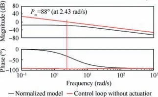
Fig.8 Bode diagrams of normalized linear model from Wf to n1 and n1 control loop with designed PI controller and without fuel flow actuator dynamics.
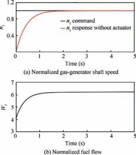
Fig. 9 Unit step response of n1 control loop with designed PI controller and without fuel flow actuator dynamics.
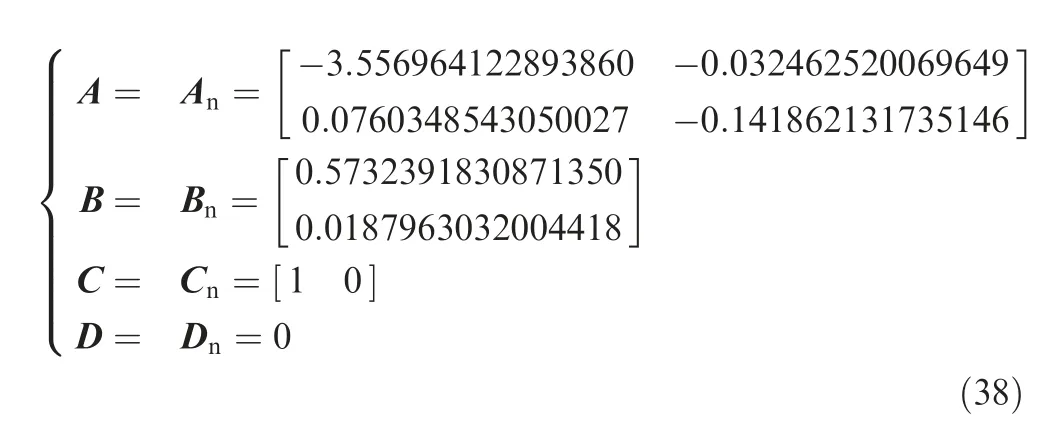
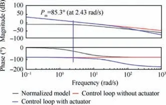
Fig. 10 Bode diagrams of n1 control loop with same PI controller and fuel flow actuator dynamics.

Fig. 8 depicts the Bode diagrams of the normalized linear model from Wfto n1(black line) and the n1control loop with the designed PI controller and without the fuel flow actuator dynamics (red line). Note that the gain margin of the red line is infinite while the phase margin (Pm) is 88° (at 2.43 rad/s).
Fig.9(a)shows the closed-loop step response of the n1control loop with the designed PI controller and without the fuel flow actuator dynamics, where the n1command (black line)represents the n1command signal. Note that the setting time is about 1.5 s (±2% tolerance band, the same blow), the percent overshoot is 0, and there is no steady state error. Fig.9(b) illustrates that the fuel flow can be controlled in time to achieve a fast step response, but the fuel flow starts from 4.02 at zero time. Therefore, the designed PI controller can basically meet the design specifications.
When the fuel flow actuator transfer function with τ=0.02 is added to the n1control loop, the Bode diagram of the n1control loop with the same PI controller and fuel flow actuator dynamics is shown in Fig.10(blue line).The blue line indicates that the fuel flow actuator dynamics has great impacts on the high frequency response of the n1control loop. Meanwhile,note that the magnitude margin of the blue line is still infinite while the phase margin is reduced to 85.3° (at 2.43 rad/s).
The closed-loop step response of n1control loop with the same PI controller and the fuel flow actuator transfer function with τ=0.02 is shown in Fig.11.Note that the fuel flow actuator output starts from zero, the step dynamic response of the red line is a little different from that of the blue line,which is n1control loop with a PI controller and without the fuel flow actuator dynamics. The setting time of the red line is about 1.435 s,the percent overshoot is 0,and there is no steady state error.
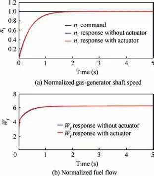
Fig. 11 Unit step response of n1 control loop with same PI controller and fuel flow actuator dynamics.
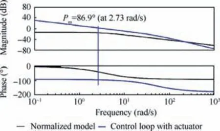
Fig. 12 Bode diagrams of n1 control loop with same PI controller and different fuel flow actuators.
Due to the small time constant of the fuel flow actuator,the step dynamic response of the n1control loop is less affected.In order to clearly explain the impacts of the fuel flow actuator dynamics on the step dynamic response of n1control loop,the Bode diagrams of the n1control loop with the same PI controller and different fuel flow actuators are shown in Fig. 12,and the corresponding closed-loop step responses are depicted in Fig.13.Figs.12 and 13 show that as the time constant of the fuel flow actuator increases, the phase margin of n1control loop with the same PI controller and the fuel flow actuator dynamics decreases, and the percent overshoot of the closedloop step response increases, resulting in worse dynamic response of the closed-loop system.Therefore,when designing the PI controller, it is necessary to consider the actuator dynamics.
To consider the actuator dynamics, the fuel flow actuator dynamics with τ = 0.02 and Eq. (38) are augmented to form a new system,as presented in Eq.(40),which is like the system described by Eq. (7). Then the single-variable PI controller is designed according to Sections 3.2-3.4. Setting c, r to 4 and 2, respectively, matrix inequality Eq. (30) is solved by using MATLAB LMI toolbox,and the PI controller gains are shown in Eq. (41).
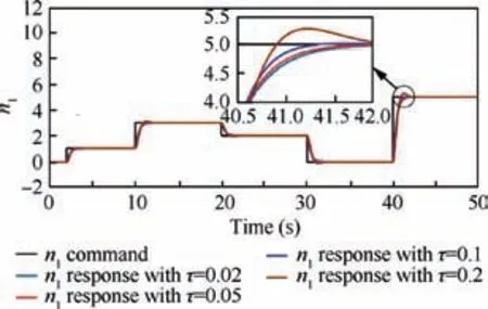
Fig.13 Step responses of n1 control loop with same PI controller and different fuel flow actuators.
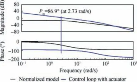
Fig. 14 Bode diagrams of normalized linear model from Wf to n1 and n1 control loop with designed PI controller and fuel flow actuator dynamics.


Fig. 14 shows the Bode diagrams of normalized linear model from Wfto n1and n1control loop with a PI controller and fuel flow actuator dynamics. Note that the gain margin is infinite while the phase margin is 86.9° (at 2.73 rad/s).
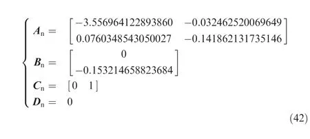
Fig.15(a) shows the closed-loop step response of the n1control loop with the designed PI controller and the fuel flow actuator dynamics. Note that the setting time is about 1.38 s,the percent overshoot is 0, and there is no steady state error.Fig.15(b) indicate that the fuel flow through the actuator can be controlled in time to achieve a fast step response.
Secondly, the normalized linear model from βpropto n2described by Eq. (42) is considered. Due to limited space, the influences of blade angle actuator dynamics on the n2control loop are not analyzed in detail.Similarly,the blade angle actuator dynamics with τ=0.05 and Eq. (42) are augmented to form a new system, as presented in Eq. (43), which is like the system described by Eq. (7). Then the single-variable PI controller is designed according to Sections 3.2-3.4. Setting c, r to 10 and 1, respectively, matrix inequality Eq. (30) is solved by using MATLAB LMI toolbox,and the PI controller gains are shown in Eq. (44).


Fig. 16 shows the Bode diagrams of the normalized linear model from βpropto n2and n2control loop with the designed PI controller and the blade angle actuator dynamics.Note that the gain margin is infinite while the phase margin changes from-21.4° (at 0.056 rad/s) of the normalized linear model to 73°(at 5 rad/s) of the n2control loop, which means that the robustness of the n2control loop is improved under the action of the designed PI controller.
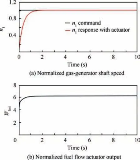
Fig. 15 Unit step response of n1 control loop with designed PI controller and fuel flow actuator dynamics.
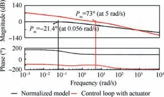
Fig.16 Bode diagrams of normalized linear model from βprop to n2 and n2 control loop with designed PI controller and blade angle actuator dynamics.
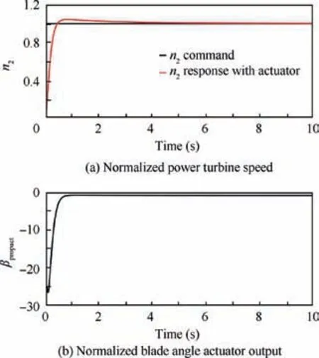
Fig. 17 Unit step response of n2 control loop with designed PI controller and blade angle actuator dynamics.
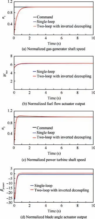
Fig.18 Unit step responses of output and input variables of two control loops with inverted decoupling.
The closed-loop step response of the n2control loop with the designed PI controller and blade angle actuator dynamics is shown in Fig.17(a).Note that the setting time is about 2.67 s, the percent overshoot is 4.21%, and there is no steady state error. Fig.17(b) illustrates that the blade angle can be controlled in time to achieve a fast step response.
According to Fig. 1, two control loops of the TSTPE with inverted decoupling are built. The closed-loop step responses of the two control loops are depicted in Fig.18. Besides, in order to clearly illustrate the impacts of the interactions between the two control loops on the step responses, the closed-loop step responses of the two single control loops are also shown in Fig. 18. Figs.18(a) and (c) show that n1and n2can track their respective commands under the action of two designed PI controllers and inverted decoupling, and the interactions between the two control loops have little influences on the n1response and n2response of the original normalized linear model, which verifies that inverted decoupling can well retain the dynamic respeonse of the original system.Moreover, note that the interactions between the two control loops have little effects on the fuel flow response, but have a significant effect on the blade angle response.
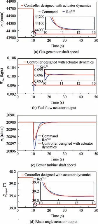
Fig. 19 Closed-loop step responses of selected output and input variables of TSTPE integrated model.
The above step response results show that there exist strong interactions between the n1control loop and n2control loop of the TSTPE, which makes it difficult to design a proper multivariable PI controller. On the contrary, it is easy to separately design a single-variable PI controller that can meet the design specifications for each control loop of the TSTPE after the interactions are effectively decoupled by using inverted decoupling.The results also illustrate that it is necessary to consider the actuator dynamics when designing a PI controller. Therefore,from the perspective of control effects,it is recommended the method of firstly using inverted decoupling and then designing a PI controller based on LMI separately for each control loop.
4.4. Testing on TSTPE integrated model
Although the designed single-variable PI controllers have achieved good control effects on the TSTPE normalized linear model, the designed PI controllers should be implemented on the TSTPE nonlinear integrated model to illustrate the effectiveness of the proposed method.Meanwhile,comparison simulations are performed between the PI controllers designed without actuator dynamics from the Ref.22and the PI controller designed with actuator dynamics based on the proposed method.
4.4.1. Design point simulation verification
Setting the flight conditions as height H=1 km and Mach number Ma=0.2, the n1command is shown in Fig.19(a).Fig.19(a) shows that compared with the PI controller from the Ref.22, the gas-generator shaft speed can track its command faster under the action of the PI controller designed in this paper, which takes about 2 s. Fig.19(b) dispalys that the fuel flow response is overshooted, slightly oscillated and then stabilized under the action of the PI controller from the Ref.22while the fuel flow tends to be asymtotically stable under the action of the PI controller designed in this paper.Fig.19(c)shows that the power turbine shaft speed can be maintained at 20900 r/min by controlling the blade angle. Note that the two transient processes are different, the deviation of the power turbine shaft speed under the action of the PI controller designed in this paper is less than that under the action of the PI controller in the Ref.22, but compared with the PI controller from the Ref.22,the power turbine shaft speed under the action of the PI controller designed in this paper tends to be stable more slowly. Fig.19(d) illustrates that compared with the PI controller from the Ref.22, the blade angle under the action of the PI controller designed in this paper tends to be stable more quickly.
4.4.2. Gain scheduling simulation verification

Fig. 20 Simulation platform of a turboprop engine.
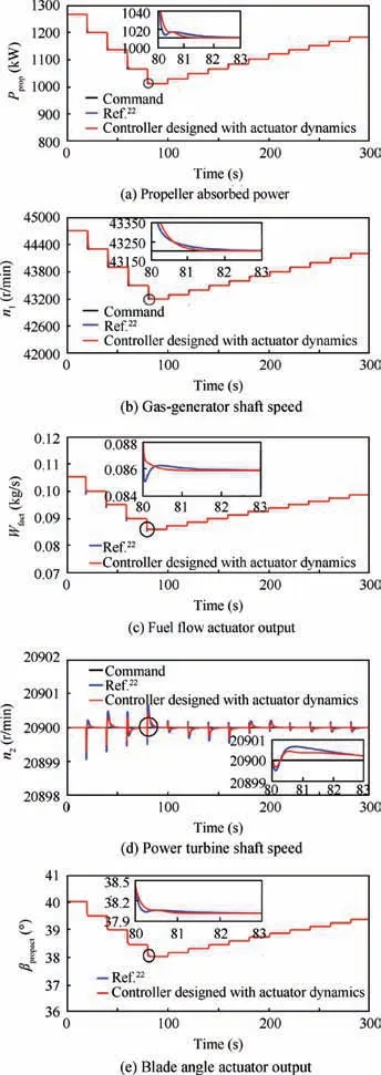
Fig. 21 Multi-step responses of selected output and input variables of TSTPE integrated model with gain scheduling.
The simulation platform of a turboprop engine is shown in Fig. 20, including flight conditions (H, Ma), Power Lever Angle (PLA), PMS, controllers (K (s )), inverted decoupling,actuators and the turboprop engine integrated model. Propeller absorbed power schedule,fuel flow schedule,blade angle schedule and a single mapping between propeller absorbed power and gas-generator shaft speed are included in PMS.Where the n1cmd, n2cmd, Wfcmdand βpropcmdrepresent the n1,n2, Wfand βpropcommand signal, respectively.
The H,Ma and PLA determine the Ppropof the TSTPE,and then the n1command is obtained via

To realize the simulation in a wide range,the gain scheduling strategy is usually employed.Since the n2is at a constant in steady-state operation, the n1is selected as the scheduling parameter in this paper, then piecewise linear interpolation is used to calculate the controller gain Kp(n1),Ki(n1)and normalized matrix An(n1), Bn(n1).
PI controllers for twelve steady-state points of the TSTPE integrated model are designed based on the proposed method.Setting flight conditions as height H=1 km, Mach number Ma=0.2, the Ppropcommand is shown in Fig.21(a), and the resulting simulated responses are shown in Fig. 21.
Fig.21(a) shows that the propeller absorbed power is able to track its command, there exists a little oscillation in its dynamic response under the action of the PI controllers from the Ref.22and gain scheduling, while it tends to be stable within 1.4 s under the action of the PI controllers designed in the paper and gain scheduling.Fig.21(b)displays that compared with the PI controllers from the Ref.22,the gas-generator shaft speed can track its command well under the action of the PI controller designed in this paper and gain scheduling, and approaches stability within 2.1 s.Fig.21(c)indicates that compared with the PI controllers from the Ref.22, the dynamic response of the fuel flow through the actuator does not oscillate,and it is stable within 1.1 s under the action of the PI controller designed in this paper and gain scheduling. Fig.21(d)illustrates that the power turbine shaft speed can be maintained at 20900 r/min by controlling the blade angle under the action of two PI controllers and gain scheduling.Note that the two transient processes are different, the deviation of the power turbine shaft speed under the action of the PI controller designed in this paper and gain scheduling is less than that under the action of the PI controller in the Ref.22and gain scheduling, but the former approaches stability more slowly than the latter. Fig.21(e) demonstrates that compared with the PI controllers from the Ref.22, the blade angle through the actuator under the action of the PI controllers designed in this paper and gain scheduling tends to be stable within 1.5 s.
To summarize, the above simulation results show that the multi-step responses of the selected output and input variables of the TSTPE integrated model under the action of the PI controllers designed in this paper and gain scheduling are better than that of the PI controllers from the Ref.22, which demonstrates that the proposed method is effective and it is necessary to consider actuator dynamics when designing controllers for the TSTPE.
5. Conclusions
(1) The open-loop responses of the selected output variables to a unit step in each input variable shows that there exist strong interactions between different control loop of a turboprop engine,and the open-loop response time of the gas-generator shaft speed to the fuel flow is great different from that of the power turbine shaft speed.
(2) The controller design procedure is presented in this paper,and can be used to design a multi-variable PI controller or single-variable PI controller for a turboprop engine. Due to the difference in the response times of the gas-generator shaft speed and the power turbine shaft speed, it is difficult to design a proper multivariable PI controller for a turboprop engine.
(3) A systematic method of designing controllers for a turboprop engine with actuator dynamics is developed in this paper, that is, the interactions are first decoupled by using inverted decoupling and then the controllers are designed via LMI, and should be easy to implement in engineering.
(4) The simulation results indicate that compared with the PI controller designed without actuator dynamics, the PI controller designed with actuator dynamics enable the gas-generator shaft speed and the power turbine shaft speed of a turboprop engine to track their respective commands by controlling fuel flow and blade angle with a better performance.
(5) Future works will improve the PMS and focus on applying the advanced control on turboprop engines.
Acknowledgements
The authors would like to thank the anonymous reviewers for their critical and constructive review of the manuscript, which helped to improve the quality of this paper.
 CHINESE JOURNAL OF AERONAUTICS2020年6期
- CHINESE JOURNAL OF AERONAUTICS的其它文章
- A novel variable structure multi-model approach based on error-ambiguity decomposition
- Multi-block SSD based on small object detection for UAV railway scene surveillance
- A new online modelling method for aircraft engine state space model
- Cross-sectional deformation of H96 brass double-ridged rectangular tube in rotary draw bending process with diあerent yield criteria
- Application of a PCA-DBN-based surrogate model to robust aerodynamic design optimization
- Numerical exploration on the thermal invasion characteristics of two typical gap-cavity structures subjected to hypersonic airflow
