Investigation on nonlinear lateral-torsional coupled vibration of a rotor system with substantialunbalance
Jie HONG, Pingcho YU, Ynhong MA,*, Dyi ZHANG,c
a School of Energy and Power Engineering, Beihang University, Beijing 100083, China
b Collaborative Innovation Center of Advanced Aero-Engine, Beihang University, Beijing 100083, China
c Beijing Key Laboratory of Aero-Engine Structure and Strength, Beijing 100083, China
KEYWORDS Instability;Lateral-torsional coupled vibration;Lock-in phenomenon;Modes;Unbalanced rotor
Abstract Substantial unbalance may be caused by fan blade off during the operation period of gas turbine engines,and related dynamic problems are very critical to the safety design of rotor system in aero-engine. This article aims to understand lateral-torsional coupled vibration of the rotor system with substantial unbalance. The governing equation of a modified unbalanced rotor system is established based on Lagrangian approach.Then,a mathematical analytical method is proposed in which a linear approximation is derived and the Floquet theory and Hill’s method are incorporated,from which the modal characteristics of the unbalanced rotor are obtained. The modal characteristics of the unbalanced rotor system are revealed comprehensively for the first time.Furthermore,the relation between the modes and responses of the unbalanced rotor is discussed in detail. The results show that the lateral vibration and torsional vibration of the unbalanced rotor are coupled through the inertial terms in the governing equations.Due to the coupling,veering and lock-in phenomena occur between the frequencies of the forward whirl mode and the torsional mode.Furthermore, lock-in can lead to a kind of principal instability. With regard to the response of the unbalanced rotor, both natural vibration components and enforced vibration components appear in the lateral response,while only natural vibration components appear during torsional vibration.Moreover, natural vibration components play a crucial role in the response within the principal instability region and cause divergence of the vibration amplitudes in the lateral and torsional directions.
1. Introduction
Substantial unbalance is a real possibility during the operation period of gas turbine engines, and it may be caused by fan blade off, bird strike, and so on1,2. Because of substantial unbalance loads generated on the spinning rotor, several secondary structural failures such as rotor instability and bearing damage may occur.In that case,how to maintain the integrity of rotor-bearing system is a major safety concern in aeroengine3,4. Substantial unbalance can cause many dynamic problems, and among these, the lateral-torsional vibration is the main focus of the present work. Unlike small unbalance that mainly causes synchronous lateral vibration5, the torsional vibration and its coupling effects with lateral vibration are extremely significant under the conditions of substantial unbalance6,7. In some more severe conditions, instability of lateral-torsional coupled vibration may be induced8. Therefore, more attention should be paid to the nonlinear lateraltorsional coupled vibration of the rotor system with substantial unbalance in the safety design of aero-engine.
Over the past several decades,many research has been performed on many aspects of the lateral-torsional coupled dynamics of the rotor system. Cohen and Porat6investigated the combined effect of resonance and coupled torsionallateral vibration using a model of an unbalanced rotor that was driven by a torsionally flexible shaft through a constant velocity joint. Following their studies, Bernasconi9established the equations of motion of a continuous shaft and analysed the bisynchronous torsional vibrations of rotating shafts. This author pointed out that the gyroscopic effect could induce 2X frequency content in the torsional vibrations. When the torsional natural frequency is close to twice the lateral natural frequency,excessive torsional vibrations at the lateral resonant frequency can appear. Applying Lagrangian dynamics, Mohiuddin10and Al-Bedoor11et al. developed models for the coupled torsional and lateral vibrations of an unbalanced rotor.A numerical method was used to integrate the equations of motion. Some nonlinear phenomena, e.g., the softening effect and energetic interaction between the lateral and torsional vibrations of the rotor, were found in the simulation results.Similar investigations were carried out by Huang12. Unlike previous work, Chu et al.13analysed the bending-torsion coupling effects of the unbalanced rotor from a new perspective.In his study, the rotor-dynamic model is established for all six Degrees of Freedom (DoF) of a rotor. Furthermore, comprehensive unbalances, including static unbalance and dynamic unbalance, as excitations were part of the model.Recently, Cao et al.14presented a nonlinear transient analysis of the combined torsional and lateral vibrations of a flexible rotor-bearing system, which included gyroscopic effects, a nonlinear short journal bearing, nonlinear short squeeze-film dampers, and external nonlinear forces/torques.
In addition to studies on the vibration characteristics of a rotor system with a single unbalance fault, there also exist a number of studies dedicated to the lateral and torsional coupled vibrations of a rotor with multiple faults, such as rubimpact15-17and cracks. Edwards et al.18, built a 3-DoF rotor model that considered both the lateral and torsional vibrations. Their results demonstrated that the torsion has a substantial influence on rotor response and should be part of the dynamic models. Al-Bedoor19also established the lateraltorsion contact model and studied the transient vibration response of a rubbing rotor. Patel et al.20developed a model that consisted of rotor and stator vibratory systems to analyse the nonlinear characteristics of a rotor intermittently coming into contact with the stator and revealed the influence of the presence of torsional vibration on the rotor response through the comparison among the spectrum cascade, bifurcation behaviour,orbit plot,etc.Considering a vertical Jeffcott rotor with a radial rub-impact, Lu and Chu21investigated, analytically and numerically, the radial and torsional vibration characteristics under typical rubbing forms, including full annular rub, partial rub and backward whirl. More recently, Mokhtar et al.22studied the rotor/stator interaction phenomenon with a finite element framework using a Lagrange multiplier-based contact mechanic approach. In their research, the rotor bending-torsional mode coupling during contact is considered,and the vibration response in both bending and torsion is analysed in detail. Zhao et al.23analysed the influences of torsional vibration on the lateral vibration of a cracked rotor. Xiao et al.24investigated the lateral-torsional vibration of a Jeffcott rotor that contained a switching transverse crack.Their studies showed that torsional vibration could significantly affect the dynamic behaviour of a rotor system by switching transverse cracks. Patel and Darpe25built a finite element model of a rotor that included both crack and rub faults. The lateraltorsional coupling was studied, and the vibration responses were analysed using the Hilbert-Huang transform.
In the studies described above, it can be noted that torsional vibration can interact with lateral vibration in many cases and,consequently,has a significant effect on the dynamic behaviour of the rotor system. This outcome means that neglecting the torsional vibration and its coupling with lateral vibration cannot accurately reflect the dynamic characteristics of the rotor system and might even produce incorrect results.Therefore, it is necessary to incorporate torsional vibration in the study of rotor dynamics. Though the lateral-torsional coupled vibration of the unbalanced rotor has attracted considerable attention, researchers have focused largely on studying the vibration responses of the unbalanced rotor by numerical integration. Furthermore, researchers tend to consider only one aspect of the rotor’s vibrations and spend little time discussing the mutual influence between lateral and torsional vibrations. Unlike these previous studies, this article means to investigate the lateral-torsional coupling effects with regard to their mode characteristics and give an insight into the relationship between the modal characteristics and vibration responses of the unbalanced rotor.The model used in this article is a modified version of the Jeffcott rotor,including unbalance excitations and nonlinearity that originates from lateraltorsional coupling. An analytical method that combines the linear simplifications and Hill’s method is developed to obtain the modes of unbalanced rotor. Then, the modal frequency,stability,and interactions between lateral modes and torsional modes are discussed comprehensively.Finally,the influence of the modes on the lateral and torsional vibration responses of the unbalanced rotor is studied in detail.
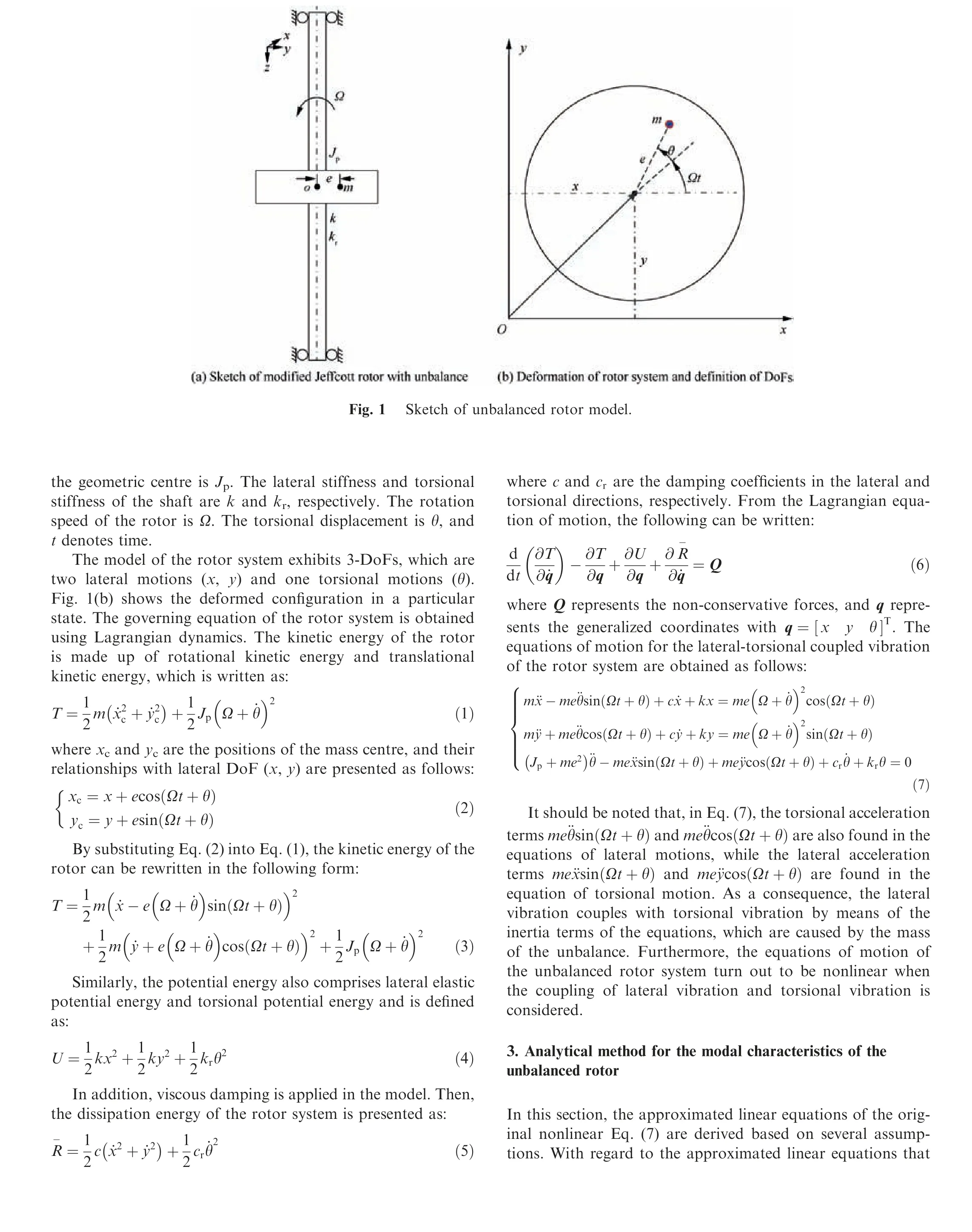
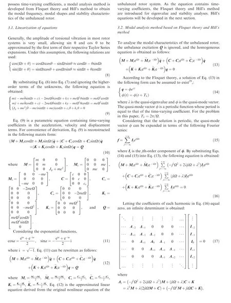
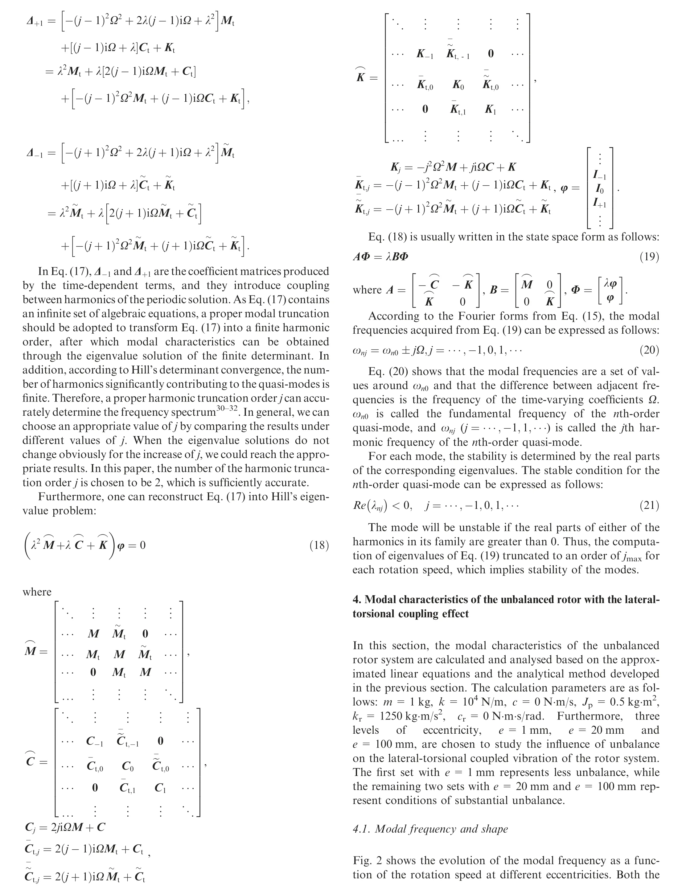
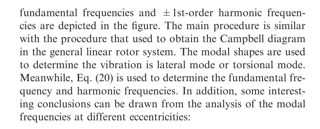
2. Dynamic model of the unbalanced rotor system with lateraltorsional coupling effects

(1) In the case of e=1 mm, the fundamental frequencies(ωb+,0,ωb-,0,ωt,0)of the forward whirl,backward whirl and torsional modes hardly change with the variation of rotation speed;their values are nearly equal to the values of the forward whirl, backward whirl and torsional modal frequencies, respectively, when the lateraltorsional coupling is ignored. Thus, one can summarize that the lateral-torsional coupling of the unbalanced rotor system with small eccentricity is very weak and can be ignored.
(2) When the eccentricity increases, the forward whirl modal frequencies and torsional frequencies begin to change, mainly in two particular regions of rotational speed. One region is approximately 470 r/min (‘‘Region A′′in Fig.2(b)and(c)).In this region,it can be seen that there exists the phenomenon of veering between the fundamental frequency of the forward whirl mode (ωb+,0)and the+1st-order harmonic frequency of the torsional mode (ωt,+1), as well as the veering between the fundamental frequency of the torsional mode (ωt,0) and the-1st-order harmonic frequency of the forward whirl mode (ωb+,-1). The veering is characterized by eigenvalue loci that more or less abruptly veer away when approaching each other, a phenomenon that is very common in vibrating structures33-35. Another region is found near a rotational speed of 1400 r/min (‘‘Region B” in Figs. 2(b) and (c)), in which the phenomenon of lock-in between ωb+,0and ωt,-1, as well as the lock-in between ωt,0and ωb+,-1, can be observed clearly.Lock-in is essentially a mirrored version of veering.When one or more parameters of the system vary, the frequencies of two modes increasingly approach each other, and, instead of veering away, they are attracted to one another and coalesce35. It is important to stress that the regions of veering and lock-in increase considerably as the eccentricity increases,while the forward whirl modal frequencies and torsional frequencies in these regions also change considerably. This finding indicates that the coupling effects between the forward whirl mode and torsional mode become significant when the rotor has substantial unbalance, and lateral-torsional coupling must be taken into account in the dynamic analysis of the unbalanced rotor. However, we must point out that the modal frequencies in the region distant from the aforementioned veering region and lock-in region are still close to their respective frequencies when lateral-torsional coupling is ignored.
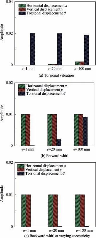
Fig. 3 Evolution of mode shapes at varying eccentricity.
(3) With regard to the backward whirl mode, it can be seen that both the fundamental frequencies and harmonic frequencies vary little as eccentricity increases, which implies that unbalance will not lead to coupling between the backward whirl mode and the torsional mode.
The mode shapes of the unbalanced rotor at a certain rotation speed—750 r/min, for example—are extracted from the solution of the eigen-problem, as shown in Fig. 3. Figs. 3(a)-(c) demonstrate the variation in the torsional vibration, forward whirl and backward whirl mode shapes, respectively, as the eccentricity increases from 1 mm to 100 mm. It should be noted the mode shapes given herein correspond to those of fundamental frequencies.Because the mode shapes of the harmonic frequencies exhibit trends similar to those of fundamental frequencies, they are not depicted below.In addition, since the eigenvectors are time-varying,their mean values in a given period are calculated and used to express the relative relation of the DoF.
One can see that,in the case of e=1 mm,lateral vibration hardly couples with torsional vibration for any modes, i.e.,there exists only torsional vibration in the torsional mode and lateral vibration in the forward/backward whirl modes.As the eccentricity increases, one can see that the amplitudes of x and y in the torsional modes and the amplitudes of θ in the forward whirl mode become increasingly large,which indicates that the coupling effect between the forward whirl mode and torsional mode is enhanced by increasing eccentricity.However, it should also be noted that the torsional vibration in the backward whirl mode hardly exists,even if the eccentricity reaches 100 mm. Hence, the backward whirl mode cannot interact with the torsional mode, which agrees with the results shown in Fig. 2.
Furthermore, the characteristics of the mode shapes across the veering region and lock-in region were analysed in detail.Fig. 4 presents a zoomed-in view of the regions of veering and lock-in when e=100 mm. In the figure, only four frequency curves, which correspond to the forward whirl modes and torsional modes within which the veering or lock-in phenomena can arise, are plotted, and the frequency curves of the backward whirl mode are not shown.
From Fig. 4(a), one can see that the veering appears between Curve 1 and Curve 2, as well as between Curve 3 and Curve 4. The mode shapes corresponding to the curves for rotation speeds 300 r/min, 450 r/min, 600 r/min and 750 r/min,respectively,are extracted and shown in Fig.5.Taking the modes shapes of Curve 1 and Curve 2 as an example,we can observe that the mode shapes of Curve 1 and Curve 2 represent torsional vibration and coupled vibration with larger lateral displacement,respectively,at Ω1=300 r/min,while the respective mode shapes shift to coupled vibration with larger lateral displacement and torsional vibration as the rotation speed reaches 700 r/min. It is obvious that the mode shape of Curve 1 at Ω1=300 r/min is nearly identical to that of Curve 2 at Ω4=700 r/min, and the mode shape of Curve 2 at Ω1=300 r/min is nearly identical to that of Curve 1 at Ω4=700 r/min. For the mode shapes of the Curve 3 and Curve 4,similar trends can be found.Therefore,we summarize by saying that the mode shapes of the frequency Curves of the unbalanced rotor undergo large changes within the veering region, which ultimately lead to an interchange of mode shapes. Moreover, it can be seen that the mode shapes of Curve 1 and Curve 3 at any rotation speed are nearly consistent, because the eigenvalues and eigenvectors of Curve 1 and Curve 3 belong to the same quasi-mode order, and the only difference is that they represent different order harmonics in the Fourier series, as shown by Eq. (15). For the same reason, the eigenvalues and eigenvectors of Curve 2 and Curve 4 are also identical.
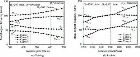
Fig. 4 Fig. 1 Zoomed-in view of veering and lock-in regions for e=100 mm.
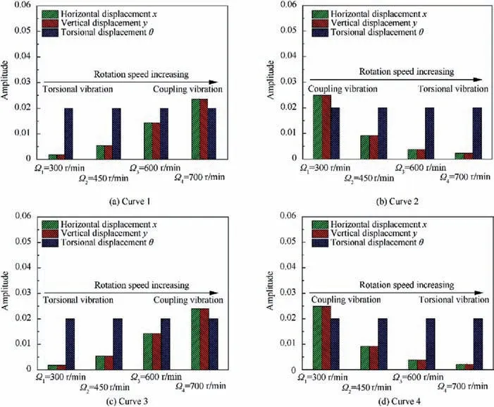
Fig. 5 Evolution of mode shapes corresponding to different curves across veering region presented in Fig. 4 (b).
Fig. 4(b) shows the lock-in phenomenon between Curve 1 and Curve 2, as well as between Curve 3 and Curve 4. The change in the mode shapes when the rotation speed passes through these lock-in regions is plotted in Fig. 6. It is important to note that the mode shapes of Curve 1 and Curve 2 (or Curve 3 and Curve 4) at the coupled point (Ω6=1500 r/min)are identical. This result indicates that, within the lock-in region, not only are the modal frequencies of the two modes equal, but the mode shapes of these two modes are also identical. At that time, the modal frequencies lock together, and these modes become and remain strongly coupled, which usually leads to the unstable behaviour of the system35.The stability characteristics of the unbalanced rotor will be discussed in Section 4.2.
4.2. Stability
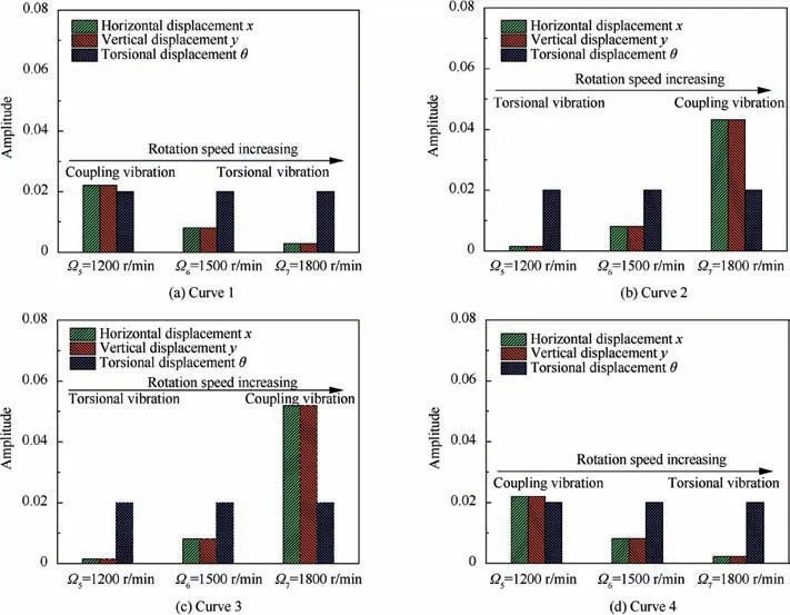
Fig. 6 Evolution of mode shapes corresponding to different curves across veering region presented in Fig. 4 (b).
Fig.7 presents the evolution of the real parts of the eigenvalue as a function of the rotation speed for e=1 mm, e=20 mm and e=100 mm. The results show that when e=1 mm, the real parts of the eigenvalue are always equal to zero, meaning that the unbalanced rotor is stable at all times.However,when the eccentricity increases to 20 mm, one instability region(Region B), where the real parts of the eigenvalue are greater than zero, arises around Ω=1400 r/min. If the eccentricity continues to increase until e=100 mm, one can see that the instability Region B increases, and that another instability region(Region C)in the neighborhood of Ω=1000 r/min also appears. These relationships indicate that the rotor system with large unbalance more easily becomes unstable over a wide region of rotation speed.
In addition, by comparing the lock-in region presented in Fig. 2 with the instability region presented in Fig. 7, we can find that the instability Region B is coincident with the lockin region. Taking the e=100 mm case as an example, the instability region corresponding to the rotation speed Points 1 and 3 (see Fig. 7(c)) is coincident with the lock-in region between the fundamental frequency of the forward whirl mode and the-1st-order harmonic frequency of the torsional mode,while the instability region corresponding to the rotation speed Points 2 and 4 is coincident with the lock-in region between the fundamental frequency of the torsional mode and the -1storder harmonic frequency of the forward whirl mode. In fact,the reason the rotor system in Region B becoming unstable owes itself to the lock-in phenomenon between the forward whirl and torsional modes, and this kind of instability region,which includes fundamental frequency coupling, is called the‘‘principal instability region”36. Moreover, another instability region, Region C (see Fig. 7(c)), corresponds to the region of rotation speed where the -1st-order harmonic frequency of the forward whirl mode is equal to zero;this kind of instability region,caused only by harmonic frequency,is named the‘‘secondary instability region”.Generally,the secondary instability region is less prejudicial for the system than the principal instability region, and it can be easily eliminated by measures such as increasing the damping of the system36. Therefore, more attention should be paid to the principal instability region in a practical rotor system.
4.3. Influence of key parameters
In rotating machines, such as aero-engines, the stiffness,mainly that of the shaft and support, is an important parameter for optimizing the dynamic characteristics of the rotor system.In addition,increasing the damping of the rotor system is the most common means by which to reduce the vibration amplitude when the rotor passes through the critical speeds.Therefore, the influence of lateral stiffness and damping on the modal characteristics of the unbalanced rotor is analysed in this section. Besides, the influence of the rotor mass is also analysed as the inertia plays an important role on the coupling effect of lateral vibration and torsional vibration. For the calculations, the eccentricity e is set to be 100 mm and the other parameters are the same as those in the previous section,except for the lateral stiffness and damping.

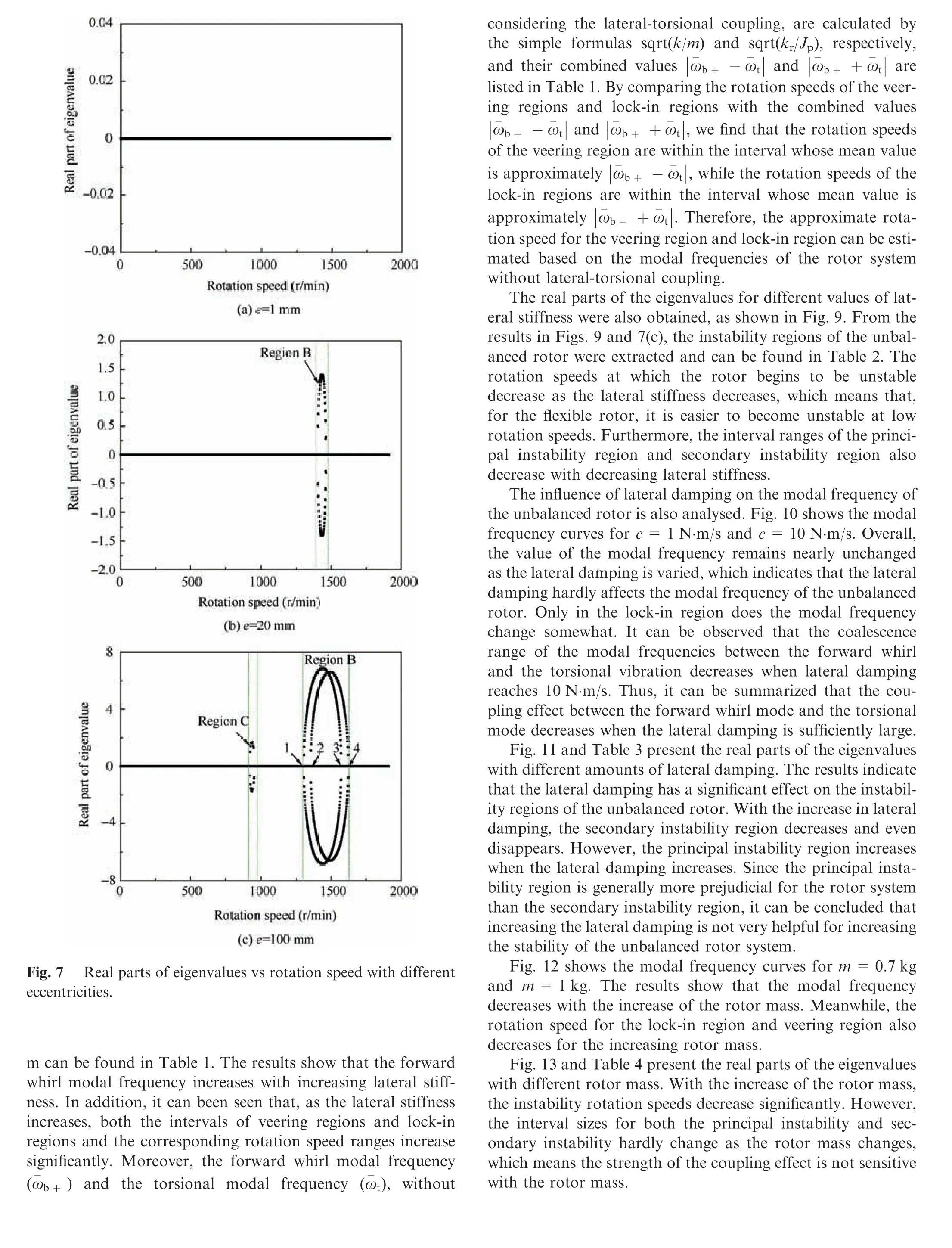
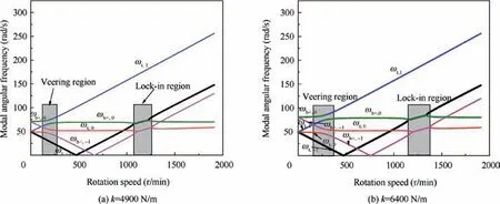
Fig. 8 Influence of rotor lateral stiffness on modal frequency.

Table 1 Range of rotation speeds for veering region and lock-in region.
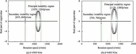
Fig. 9 Influence of rotor lateral stiffness on real part of eigenvalue.

Table 2 Instability regions of unbalanced rotor with different values of lateral stiffness.
5. Vibration responses of the unbalanced rotor with lateraltorsional coupling effect
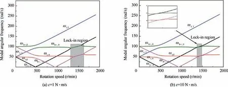
Fig. 10 Influence of rotor lateral damping on the modal frequency.
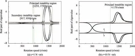
Fig. 11 Influence of rotor lateral damping on real part of eigenvalue.

Table 3 Instability regions of unbalanced rotor with varying lateral damping.
In this section,the vibration responses of the unbalanced rotor system are calculated. The following parameters used:m=1 kg, k=104N/m, c=1 N·m/s, Jp=0.5 kg·m2,kr=1250 kg·m/s2, cr=2×10⁻⁴N·m·s/rad, and e=100 mm. These parameters are essentially identical to the parameters used in the previous section, except the lateral damping and torsional damping. It should be noted that the eccentricity chosen here represents a large unbalance.Furthermore,the lateral damping and torsional damping used here are also in line with those of a real rotor system in rotating machinery. Moreover, the original nonlinear Eq. (7) is used in the calculation of the vibration response instead of the linear approximate Eq.(10),since governing Eq.(7)requires no simplification and is absolutely accurate. First, the influence of lateral-torsional coupling on the rotor’s response characteristics is analysed by means of the spectrum cascade. Then, the time-frequency responses at certain special rotation speeds are examined, and the relationship between the modal characteristics and the response characteristics of the large unbalanced rotor is obtained.
5.1. Characteristics of the spectrum cascade with the effect of lateral-torsional coupling
The lateral vibration of the unbalanced rotor is first analysed to learn about the effect of lateral-torsional coupling on the rotor’s lateral vibration. For the unbalanced rotor system, if the coupling of lateral vibration and torsional vibration is not considered, then the well-known unbalanced convergence of the solving process, and the total integration time is set to 10 s.The time response of the last 5 s is used to perform a Fast Fourier Transform (FFT) to attenuate the transient components as much as possible.Moreover,if there are no additional illustrations,the same computing procedure is used in the subsequent calculation.
The results in Fig. 14 show that only the rotational frequency component frotationexists in the response,and its amplitude reaches a maximum value at the resonance point 950 r/min,which is equal to the lateral natural frequency of the rotor system.
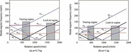
Fig. 12 Influence of rotor mass on modal frequency.
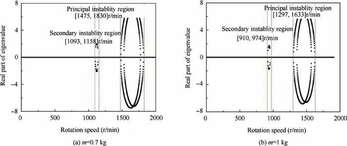
Fig. 13 Influence of rotor mass on real part of eigenvalue.

Table 4 Instability regions of unbalanced rotor with varying lateral damping.
The spectrum cascade for the case when lateral-torsional coupling is included in the calculation is shown in Fig. 15.Comparing these to the results in Fig. 14, two differences can be observed:1)when the lateral-torsional coupling is considered, some super-harmonic and sub-harmonic components appear at the supercritical rotation speed,and 2)the amplitude of the rotational frequency frotationvaries non-monotonically instead of decreasing monotonically with increasing rotation speed at the supercritical rotation speed. Fig. 16 shows a clearer comparison of the components of frotationfor the unbalanced rotor with/without lateral-torsional coupling.
To gain insight into the influence of lateral-torsional coupling on the spectrum of the lateral vibration, the results of Fig. 15 are presented in logarithmic coordinate form in Fig. 17. Meanwhile, the comparison between the modal frequency (results in Fig. 2(c)) and the frequency components in response is shown in Table 5. It can be seen that the -1storder harmonic frequency (ft,-1) and +1st harmonic frequency of torsional mode (ft,+1), and the fundamental frequency ((fb+,0)) of the forward whirl mode appear in the spectrum due to lateral-torsional coupling. The relationship between these frequencies is the same as that presented in the modal analysis in Section 4, i.e., the frequency ft,-1first decreases until it reaches 0 and then increases with increasing rotation speed. Moreover, the frequency ft,+1increases with increasing rotation speed while the veering phenomenon can be observed between ft,+1and fb+,0approximately 500 r/min in the spectrum cascade.Furthermore,we can see that the frequency response at the supercritical rotation speed is more complex, which indicates that lateral-torsional coupling more significantly affects the lateral response at the supercritical rotation speed.
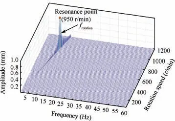
Fig. 14 Spectrum cascade of lateral vibration for unbalanced rotor without considering lateral-torsional coupling.
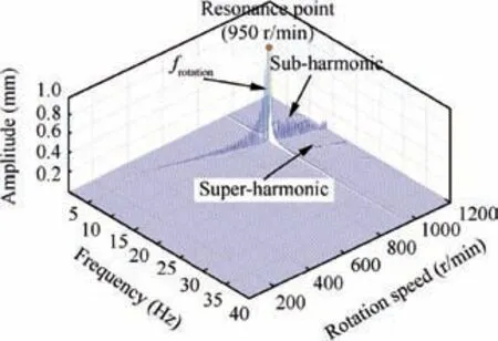
Fig. 15 Spectrum cascade of lateral vibration for unbalanced rotor including lateral-torsional coupling.
For the torsional vibration, if lateral-torsional coupling is not considered,there will be no response because no excitation exists in the torsional direction (see Eq. (7)). When the coupling effect is taken into account, the torsional vibration is obtained, as shown in Fig. 18. From Fig. 18(a), one can see that the torsional vibration at subcritical rotation speed is very small, meaning that the lateral-torsional effect at that time is weak. As the rotation speed increases, the rotor first passes through the secondary instability region, in which the fb+,-1(0 Hz) is excited. Meanwhile, the amplitude of fb+,-1is very large, which may be due to the instability features in this region. In the region of supercritical rotation speed, obvious torsional vibration can be observed, and the main component in the frequency domain is the fundamental frequency (ft,0) of the torsional mode. Additionally, it is important to note that there is no rotational frequency component in the frequency domain of the torsional vibration. This finding suggests that synchronous vibration in the lateral direction cannot interact with the torsional vibration through the coupling effects.
Fig. 18(b) shows the spectrum cascade of torsional vibration in logarithmic coordinate form. One can see that frequencies of ft,0and fb+,-1exist in the frequency domain.The veering phenomenon between ft,0and fb+,-1can also be observed in the spectrum cascade of torsional vibration.
5.2. Response characteristics at certain rotation speeds
The time-frequency response at certain special rotation speeds is examined in this section. The rotation speeds are chosen from the veering region, secondary instability region, and the principal instability region.
Fig. 19 shows the vibration response of the unbalanced rotor at rotation speeds near or within the veering region.The selected rotation speeds are 300 r/min, 480 r/min and 670 r/min. When unbalance excitation is applied to the rotor,both the modal vibration contents and the enforced vibration content appear in the lateral vibration. The modal vibration contents mainly include the components of fb+,0and ft,+1.From the time response, we can see that the modal vibration contents attenuate as time passes. Therefore, the amplitude of the modal frequency components decreases further and further.For the torsional vibration,only the modal vibrations are excited by the unbalance excitation. The main components in the frequency domain involve fb+,+1and ft,0. The torsional vibrations also attenuate;however,the decay rates at different rotation speeds are different.It is obvious that the decay rates within the veering region (480 r/min) are greater than those outside the veering region (300 r/min and 670 r/min).
The vibration responses in the secondary instability region are presented in Fig. 20. For lateral vibration, the amplitude increases continuously over time, and the primary frequency content comes from frotation. In fact, this rotation speed corresponds precisely to the resonance point of the rotor system,and the lateral vibration exactly demonstrates resonance.The amplitude will become stable until the energy input by the unbalance excitation is equal to that dissipated by damping. For torsional vibration, the amplitude also increases continuously, but the value is negative at all times. The results in the frequency domain indicate that fb+,-1(0 Hz) is the main component. According to the modal analysis in Section 4,the secondary instability region is caused by the harmonic frequency fb+,-1. This finding implies that the instability of the-1st-order harmonic frequency of the forward whirl mode(fb+,-1) is the main reason that the value of the torsional amplitude is negative, ultimately leading to divergence of the torsional amplitude. As illustrated in Section 4.3, the secondary instability region can be easily eliminated by increasing the lateral damping; hence, the torsional amplitude in this region can also be restricted by increasing the lateral damping.Moreover, we must point out again that the reasons for the divergence of the lateral vibration amplitude and torsional vibration amplitude are different. The former phenomenon is due to the resonance of lateral vibration at the critical speed,while the latter is caused by the instability of the natural modal vibration.
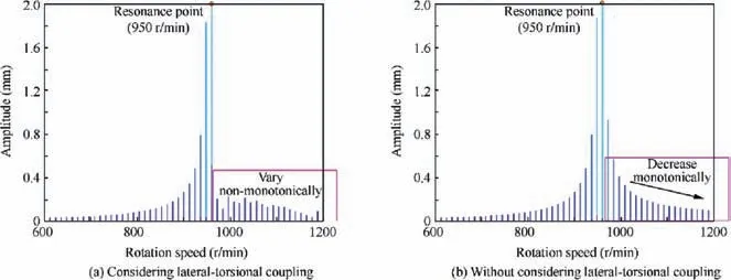
Fig. 16 Amplitude of rotational frequency component for lateral vibration of unbalanced rotor.
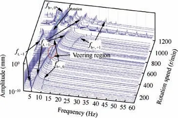
Fig. 17 Spectrum cascade of lateral vibration in logarithmic coordinate form including lateral-torsional coupling.
The vibration responses at the supercritical rotation speed(1200 r/min) were also obtained, as shown in Fig. 21. It can be observed that the response characteristics of the lateral and torsional vibration are similar to those in Fig. 19. However, the decay rate seems to decrease to a value lower than those at the subcritical rotation speeds.
If the rotation speed continues to increase, the rotor enters the principal instability region; the vibration responses in this region are shown in Fig.22.It can be seen that the amplitudes of both lateral vibration and torsional vibration increase over time, indicating divergence of the rotor’s vibration in this region.The frequency results show that multiple natural mode components,such as ft,-1and ft,+1,and the enforced vibration component frotationexists in the frequency domain of lateral vibration.Among these,the amplitude of ft,-1is highest,which indicates that the divergence of the lateral response may be due to the instability of this mode. For torsional vibration, the main frequency component is ft,0,and the corresponding mode may be the factor that results in the divergence of the torsional response.
To examine the relationships among the above frequency components over time and gain insight into the factors contributing to the instability of the rotor’s vibration, a timefrequency analysis for the time responses was performed using the wavelet transform in MATLAB, as shown in Figs. 23 and 24. The wavelet transform provides a time-frequencydependent window, which allows the frequency components of the response at different moments to be easily observed.From Fig. 23, it can be seen that the amplitude of ft,-1increases with time, while the amplitudes of the other frequency components decrease or remain nearly constant. This finding means that the instability of lateral vibration is due to the instability of the ft,-1mode. In fact, this kind of instability is caused by the lock-in of ft,-1and fb+,0,which was discussed in Section 4.Similarly, the reason for the divergence of torsional vibration is the instability of ft,0based on the result in Fig. 24, and this kind of instability is caused by the lock-in of ft,0and fb+,-1.It is important to note that this kind of instability cannot usually be eliminated or reduced by increased damping. However, the results in Section 4.3 indicate that the principal instability region is essentially determined by the sum of the lateral natural frequency and torsional natural frequency. Therefore, for a practical rotor system, we can improve the lateral natural frequency or torsional frequency and reduce the operating rotation speed below the principal instability region.

Table 5 Comparison of modal frequency and frequency components in response under different rotation speeds.
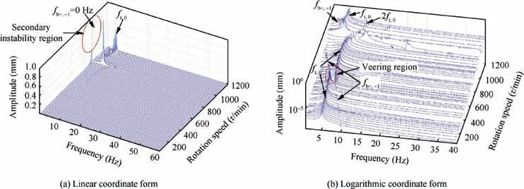
Fig. 18 Spectrum cascade of torsional vibration for unbalanced rotor including lateral-torsional coupling.
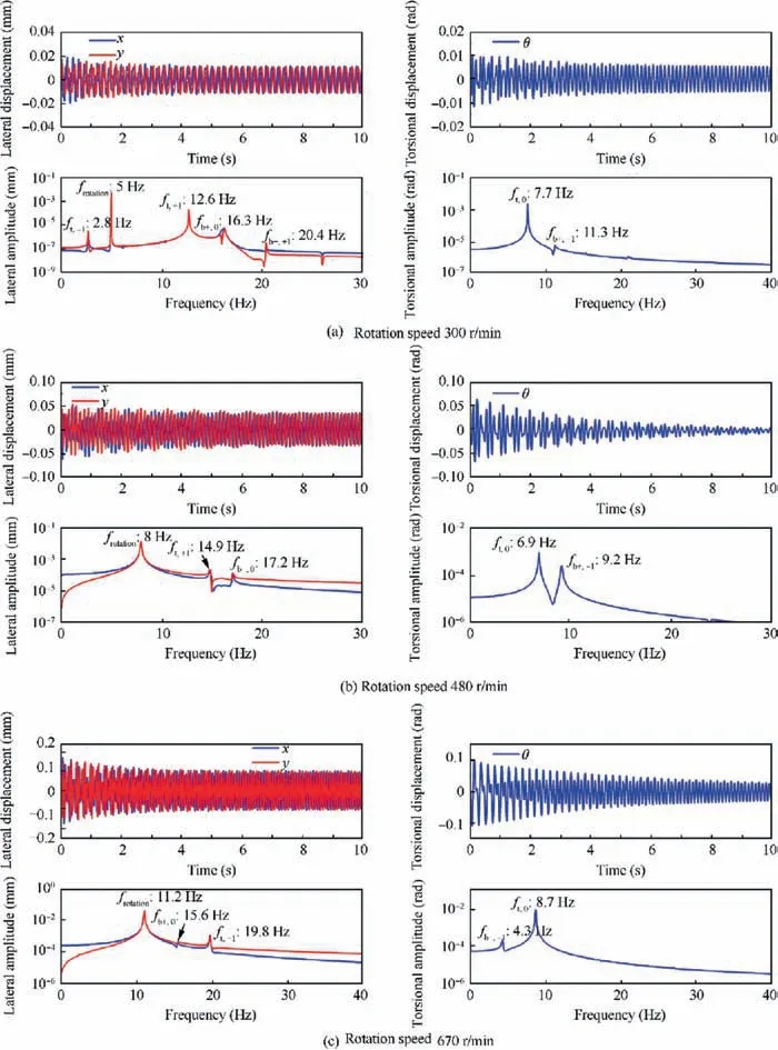
Fig. 19 Vibration responses at different rotation speeds near or within veering region.
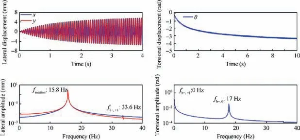
Fig. 20 Vibration responses at rotation speed in secondary instability region (950 r/min).
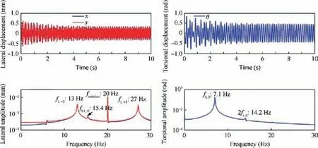
Fig. 21 Vibration responses at supercritical rotation speed (1200 r/min).
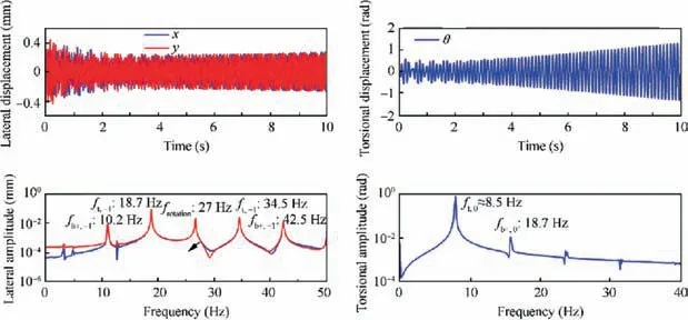
Fig. 22 Vibration responses at rotation speed in principal instability region (1600 r/min).
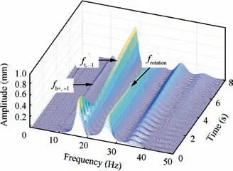
Fig. 23 Wavelet diagram of lateral response in Fig. 22.
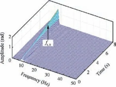
Fig. 24 Wavelet diagram of torsional response in Fig. 22.
6. Conclusion
This article systematically and comprehensively investigates the effect of lateral-torsional coupling caused by substantial unbalance on the modal characteristics and response characteristics of the rotor system.The governing equation of a modified unbalanced rotor system is established via Lagrangian dynamics,which reveals that,for the unbalanced rotor,lateral vibration couples with torsional vibration through the inertial terms. With regard to the modal characteristics of the unbalanced rotor, one analytical method is proposed that involves derivation of a linear approximation and incorporating the Floquet theory and Hill’s method.
Based on the proposed method, the lateral-torsional coupling effects are discussed in detail from the modal point of view.It is found that both the fundamental frequency and harmonic frequency exist in the spectrum of natural vibration.The difference between fundamental frequency and harmonic frequency depends on the rotation speed of the rotor system.In addition, the modal analysis shows that there exists a veering phenomenon and a lock-in phenomenon between the fundamental frequency(harmonic frequency)of the forward whirl mode and the harmonic frequency(fundamental frequency)of the torsional mode. In these regions, the coupling effect between lateral vibration and torsional vibration is remarkable. Consequently, the modal frequency and modal shapes of the unbalanced rotor change significantly. Furthermore,the lock-in between the forward mode and the torsional mode results in a principal instability region,which can endanger the safe operation of the rotor system. From the analysis of the influence of key parameters,it can be summarized that the lateral stiffness has a significant effect on the veering region and lock-in region.
Based on the numerical method used, the relationship between the modes and the lateral/torsional vibration is studied from the point of view of response.It is found that both the natural vibration components (ft,-1, ft,+1, fb+,0, etc.) and the enforced vibration component (frotation) appear in the frequency domain of lateral vibration. For torsional vibration,only natural vibration components (ft,0, fb+,0, fb+,-1, etc.)appear in the frequency domain. In the principal instability region, the natural vibration components determine the responses in the lateral and torsional directions and ultimately lead to divergence of their amplitudes.
Acknowledgements
The authors would like to acknowledge the support from the National Natural Science Foundation of China (Nos.11772022, 51575022 and 51475021), and Pingchao Yu would like to acknowledge the support by the Academic Excellence Foundation of BUAA for Ph.D. Students.
 CHINESE JOURNAL OF AERONAUTICS2020年6期
- CHINESE JOURNAL OF AERONAUTICS的其它文章
- A novel variable structure multi-model approach based on error-ambiguity decomposition
- Multi-block SSD based on small object detection for UAV railway scene surveillance
- A new online modelling method for aircraft engine state space model
- Cross-sectional deformation of H96 brass double-ridged rectangular tube in rotary draw bending process with diあerent yield criteria
- Application of a PCA-DBN-based surrogate model to robust aerodynamic design optimization
- Numerical exploration on the thermal invasion characteristics of two typical gap-cavity structures subjected to hypersonic airflow
