Application of improved active disturbance rejection control algorithm in tilt quad rotor
Zhigang WANG, Hong ZHAO, Dengyan DUAN, Yuanyang JIAO, Jianbo LI
National Key Laboratory of Rotorcraft Aeromechanics, Nanjing University of Aeronautics and Astronautics, Nanjing 210016, China
KEYWORDS Active disturbance rejection control;Adaptive sliding mode control;Explicit model;Radial basis function neural network;Tilt quad rotor
Abstract The Tilt Quad Rotor(TQR)has complex dynamics characteristics,especially in conversion mode.It is difficult to build the dynamic model of the TQR and the environmental factors have a great influence on it.To solve the problem of control in conversion mode of TQR,this paper carries out the design of the controller based on improved Active Disturbance Rejection Control(ADRC). According to the characteristics of flight in conversion mode, Tracking Differentiator(TD) with explicit model is used to solve the problem of multiple integrals when the system is high-order system. Extended State Observer (ESO) with Radial Basis Function (RBF) neural network is used to estimate and compensate for internal and external uncertainties, and the adaptive sliding mode control in Nonlinear State Error Feedback(NLSEF) is used to improve the response speed of the controller and reduce the parameters which should be tuned.Through the flight control simulation of the TQR, the validity and rationality of the control system are verified.
1. Introduction
The Tilt Quad Rotor (TQR) has the advantages of hovering and landing like helicopter, and flying at high speed like fixed wing aircraft, in both military and civilian use. Because it has the flight characteristics of helicopter and fixed wing UAV,the design of its flight control system is the focus and difficulty for researching the TQR.1-7The TQR is generally equipped with both the helicopter and the fixed wing operating system,which will bring the manipulation coupling problem. Especially in the conversion mode, the coupling of longitudinal and lateral manipulation is heavy,the dynamic model is difficult to design and the environment has great influence on the flight dynamics. Therefore, solving the problem of manipulation coupling while realizing the stable control of TQR during conversion mode is one of the key technologies of TQR.

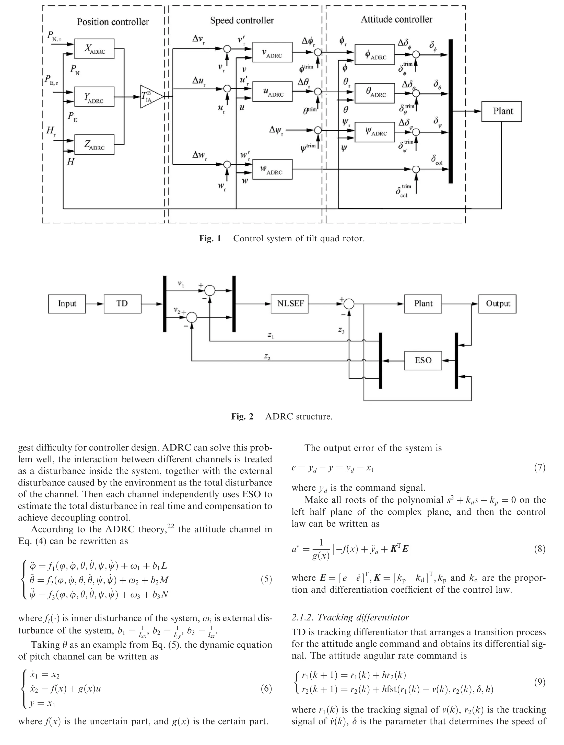
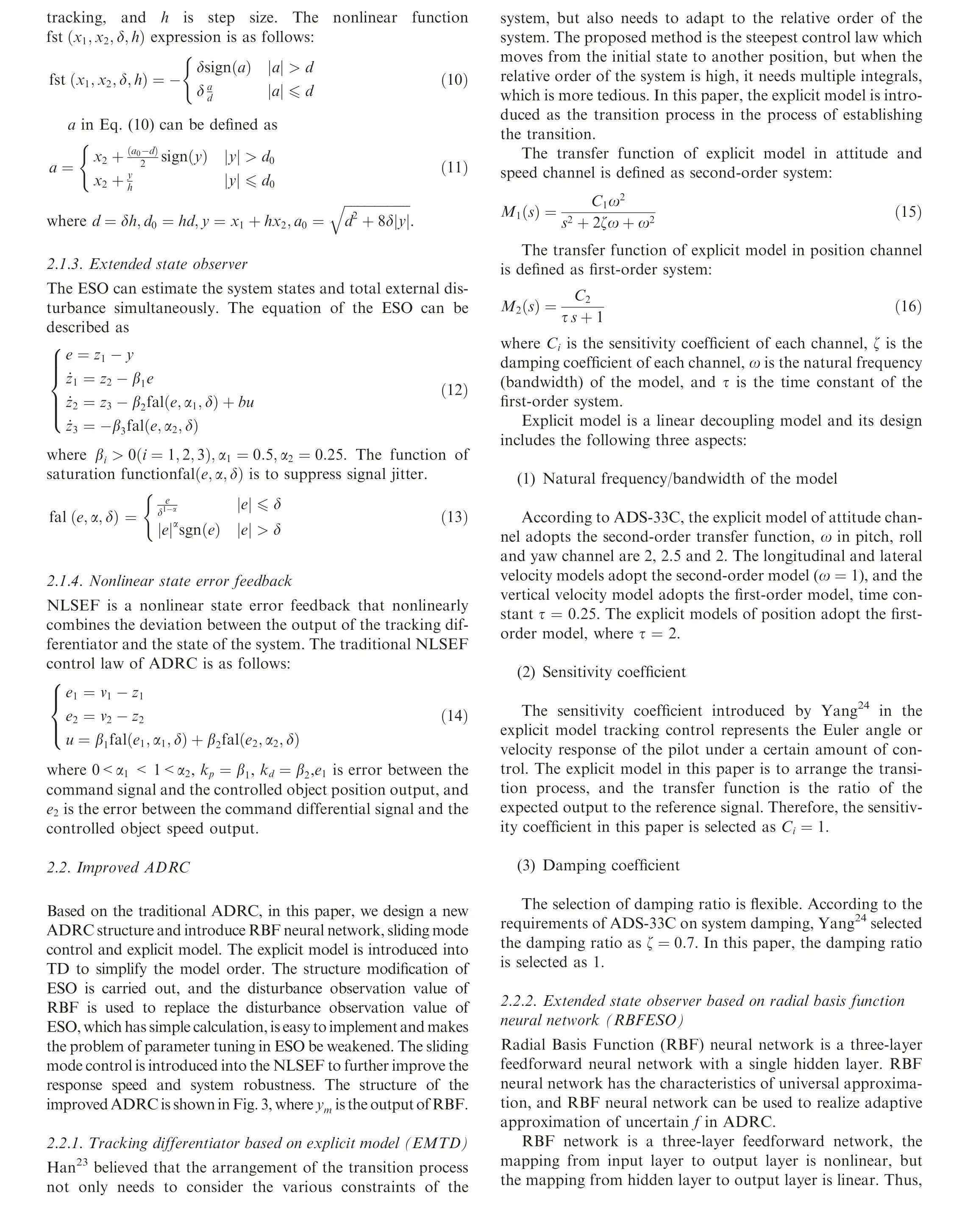
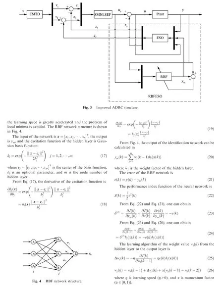
3. Simulation results and analysis
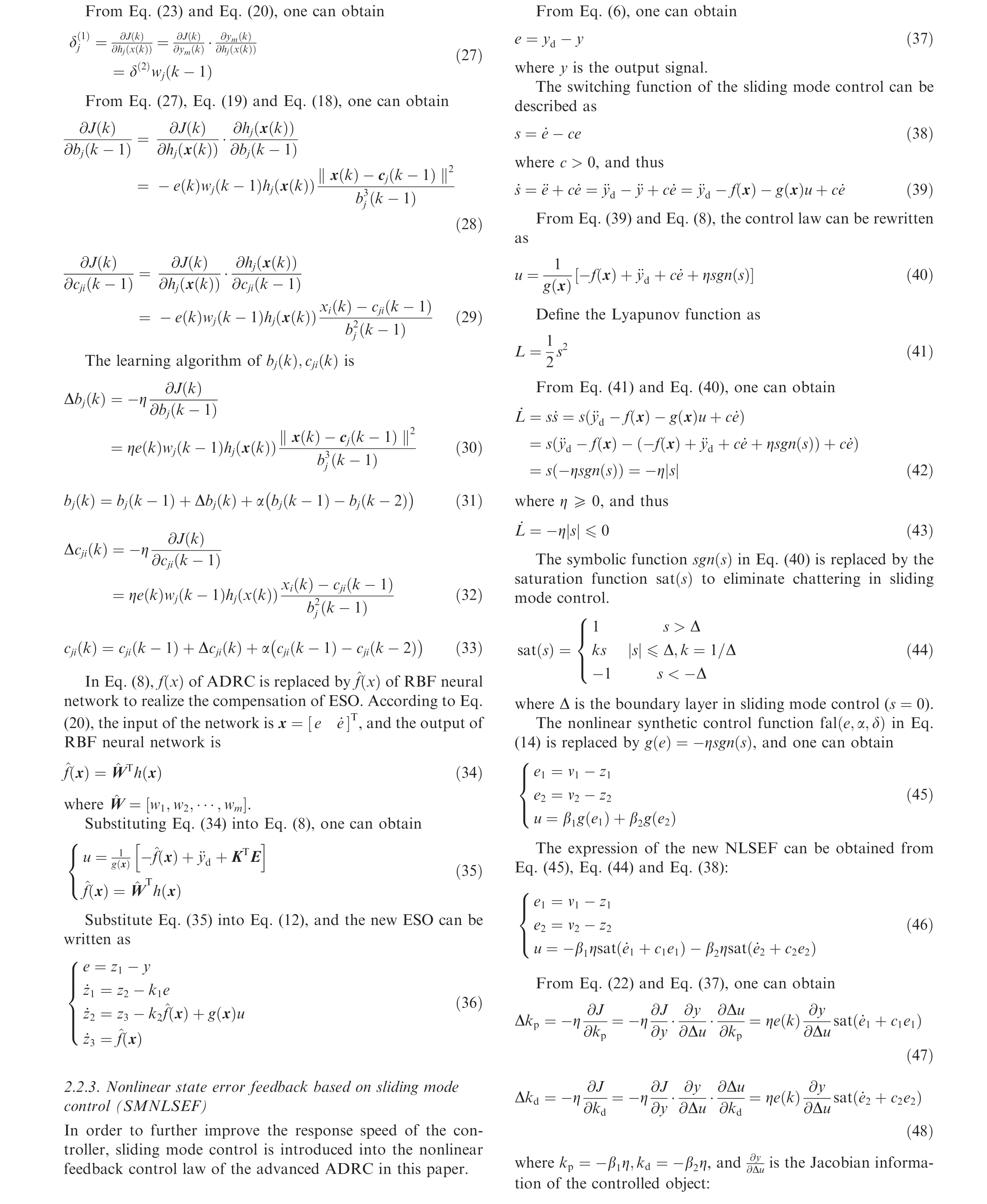
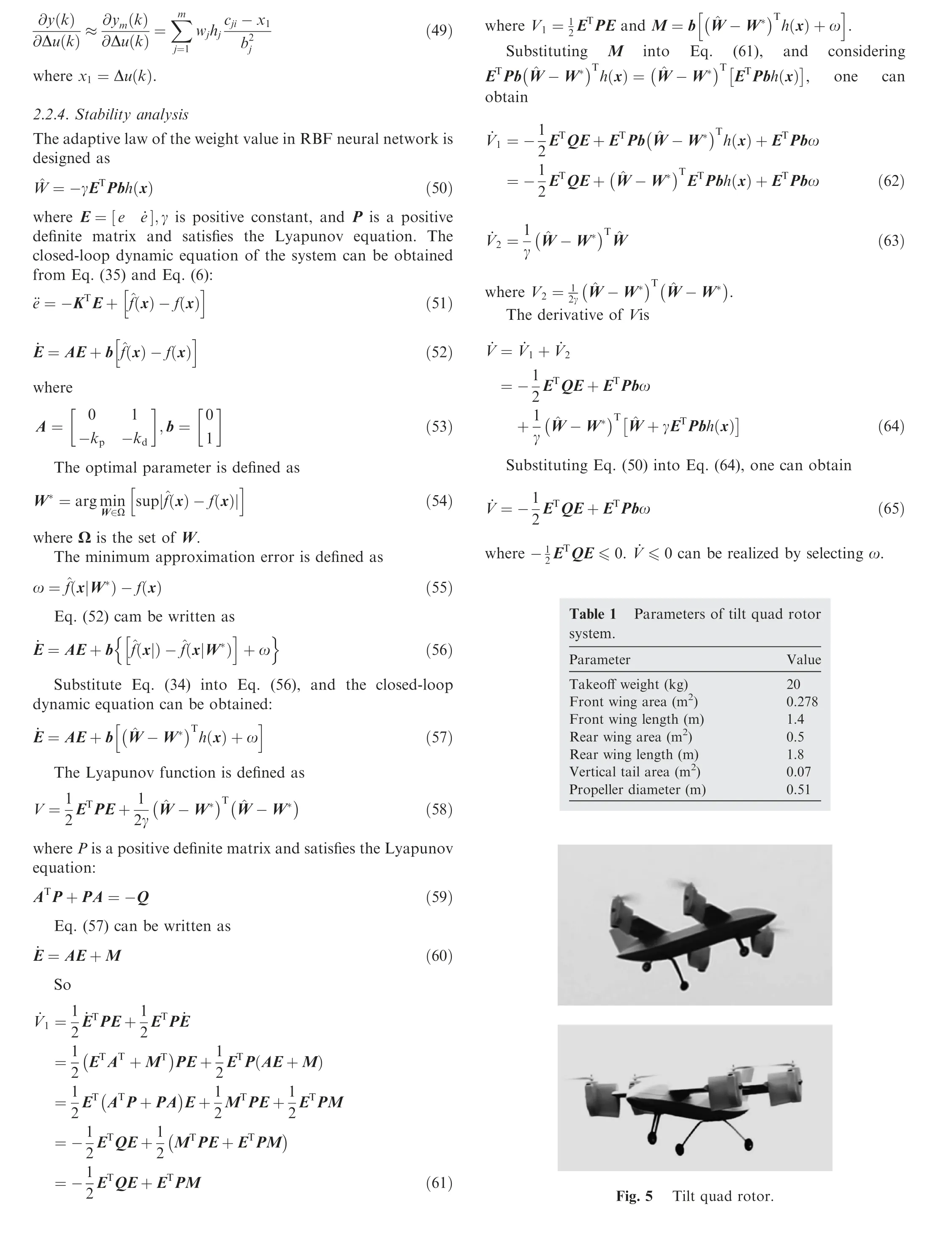
In this paper, the tilt quad rotor conversion mode is taken as the control object, and the numerical simulation verification is carried out when the nacelle tilt angle is 0°, 30°, 60° and 90°. The parameters of the TQR UAV are shown in Table 1.Fig. 5 is the flight experiment of the tilt quad rotor. The state space of the control object is shown in Appendix A. In the Appendix A,if some value in the matrix is too small,we write the value as 0.00 or -0.00. In the state space, the state vectors are x= [u v w p q r φ θ ψ] and the control vectors are u= [δTδEδAδRβm], where δTis throttle manipulation, δE, δAand δRare longitudinal, lateral and course manipulation respectively, and βmis tilt angle.
The command signal of the three attitude angles is step signal with amplitude of 1, and the external disturbance signal is 1.2sin (t ). The simulation results under the traditional ADRC,improved ADRC and PD controller are shown in Figs. 6-11 and Tables 2-4. In these figures, y, dy and x3are the output of position signal, speed signal and the total disturbance respectively. In these figures, z1, z2and z3are the estimation of y, dy and x3respectively.
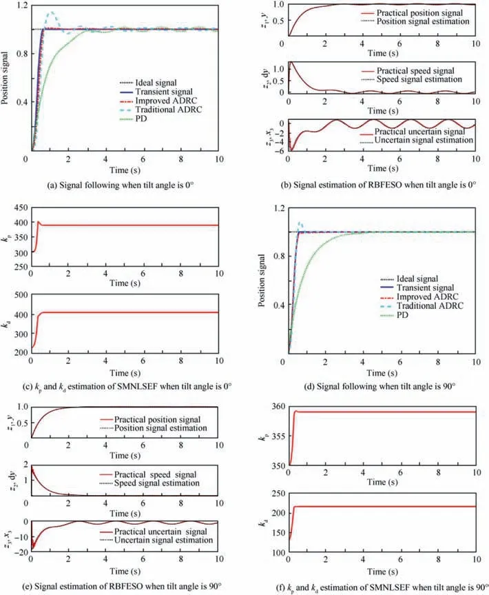
Fig. 6 Pitch channel in helicopter and fixed wing mode.
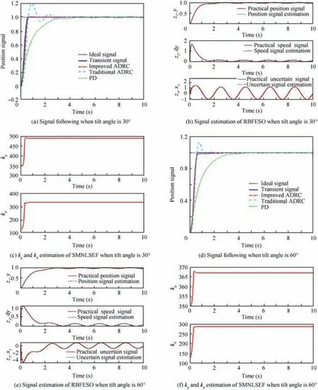
Fig. 7 Pitch channel in conversion mode.
It can be seen from Fig. 6 and Table 2 that the adjustment time of traditional ADRC, improved ADRC and PD controller in helicopter mode are about 2 s, 0.6 s and 3 s respectively. The system overshoot of traditional ADRC and improved ADRC is about 15% and 1% respectively; however the PD controller almost has no overshoot. The estimation of position,speed and uncertain part are well fitted with the practical ones. After self-tuning of kpand kdin SMNLSEF, the two parameters are 390 and 410. From the curves of the simulation results in fixed wing mode, we can see that the adjustment time of the traditional ADRC,improved ADRC and PD controller in helicopter mode are about 0.5 s, 0.5 s and 2.6 s respectively. The system overshoot of traditional ADRC is about 8%; however the improved ADRC and PD controller almost have no overshoot. The estimation of position, speed and uncertain part are well fitted with the practical ones.After self-tuning of kpandkdin SMNLSEF, the two parameters are 359 and 215.
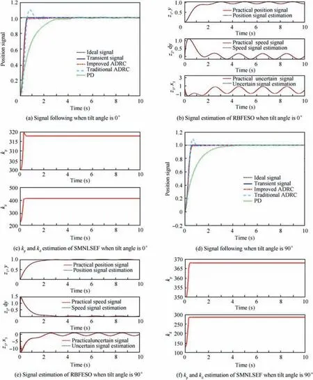
Fig. 8 Roll channel in helicopter and fixed wing mode.
It can be seen from Fig.7 and Table 2 that,when tilt angle is 30°, the adjustment time of traditional ADRC, improved ADRC and PD controller are about 0.5 s, 0.5 s and 2.8 s respectively. The system overshoot of traditional ADRC is about 20%; however the PD controller and improved ADRC almost have no overshoot. The estimation of position, speed and uncertain part are well fitted with the practical ones.After self-tuning of kpand kdin SMNLSEF,the two parameters are 495 and 320. From the curves of the simulation results when tilt angle is 60°,we can see that the adjustment time of the traditional ADRC, improved ADRC and PD controller in helicopter mode are about 0.6 s, 0.6 s and 2.8 s respectively. The system overshoot of traditional ADRC is about 15%;however the improved ADRC and PD controller almost have no overshoot.The estimation of position,speed and uncertain part are well fitted with the practical ones. After self-tuning of kpand kdin SMNLSEF, the two parameters are 368 and 285.
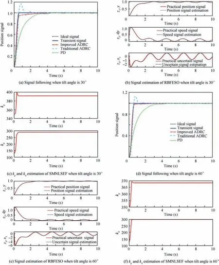
Fig. 9 Roll channel in conversion mode.
It can be seen from Fig. 8 and Table 3 that the adjustment time of traditional ADRC, improved ADRC and PD controller in helicopter mode are about 0.5 s, 1 s and 3 s respectively. The system overshoot of traditional ADRC is about 10%; however the PD controller and improved ADRC almost have no overshoot. The estimation of position, speed and uncertain part are well fitted with the practical ones.After self-tuning of kpand kdin SMNLSEF,the two parameters are 405 and 318.From the curves of the simulation results in fixed wing mode, we can see that the adjustment time of the traditional ADRC, improved ADRC and PD controller in helicopter mode are about 0.5 s, 0.5 s and 2.9 s respectively. The system overshoot of traditional ADRC is about 10%;however the improved ADRC and PD controller almost have no overshoot.The estimation of position,speed and uncertain part are well fitted with the practical ones. After self-tuning of kpand kdin SMNLSEF, the two parameters are 368 and 285. It can be seen from Fig. 9 and Table 3 that when tilt angle is 30°,the adjustment time of traditional ADRC, improved ADRC and PD controller are about 0.5 s, 0.5 s and 2.5 s respectively.The system overshoot of traditional ADRC is about 18%;however the PD controller and improved ADRC almost have no overshoot.The estimation of position,speed and uncertain part are well fitted with the practical ones.After self-tuning of kpand kdin SMNLSEF, the two parameters are 395 and 295.From the curves of the simulation results when tilt angle is 60°,we can see that the adjustment time of the traditional ADRC,improved ADRC and PD controller in helicopter mode are about 0.6 s, 0.6 s and 2.9 s respectively. The system overshoot of traditional ADRC is about 16%; however the improved ADRC and PD controller almost have no overshoot.The estimation of position, speed and uncertain part are well fitted with the practical ones. After self-tuning of kpand kdin SMNLSEF, the two parameters are 368 and 300.
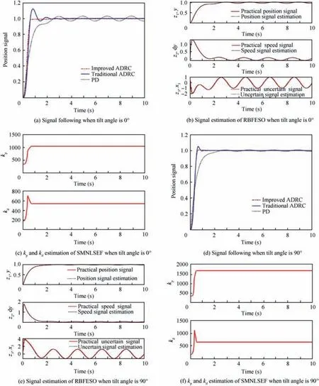
Fig. 10 Yaw channel in helicopter and fixed wing mode.
It can be seen from Fig.10 and Table 4 that the adjustment time of traditional ADRC, improved ADRC and PD controller in helicopter mode are about 0.6 s, 0.6 s and 2.7 s respectively. The system overshoot of traditional ADRC and improved ADRC are about 30% and 2% respectively;however the PD controller almost has no overshoot. The estimation of position, speed and uncertain part are well fitted with the practical ones. After self-tuning of kpand kdin SMNLSEF, the two parameters are 1000 and 580. From the curves of the simulation results in fixed wing mode, we can see that the adjustment time of the traditional ADRC,improved ADRC and PD controller in helicopter mode are about 0.5 s, 0.6 s and 3.2 s respectively. The system overshoot of traditional ADRC is about 20%; however the improved ADRC and PD controller almost have no overshoot.The estimation of position, speed and uncertain part are well fitted with the practical ones. After self-tuning of kpand kdin SMNLSEF, the two parameters are 1700 and 700.
It can be seen from Fig.11 and Table 4 that,when tilt angle is 30°, the adjustment time of traditional ADRC, improved ADRC and PD controller are about 0.7 s, 0.7 s and 2.9 s respectively. The system overshoot of traditional ADRC is about 19%; however the PD controller and improved ADRC almost have no overshoot. The estimation of position, speed and uncertain part are well fitted with the practical ones.After self-tuning of kpand kdin SMNLSEF,the two parameters are 720 and 560. From the curves of the simulation results when tilt angle is 60°,we can see that the adjustment time of the traditional ADRC, improved ADRC and PD controller in helicopter mode are about 2 s, 0.6 s and 2.9 s respectively. The system overshoot of traditional ADRC is about 20%;however the improved ADRC and PD controller almost have no overshoot.The estimation of position,speed and uncertain part are well fitted with the practical ones. After self-tuning of kpand kdin SMNLSEF, the two parameters are 950 and 800.
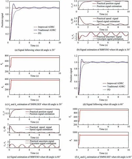
Fig 11 Yaw channel in conversion mode.
We can see from Fig. 6-11 that the simulation results of improved ADRC are much better than those of the traditional ADRC and PD controller. The improved ADRC can quickly follow the transient signal, and almost has no system over-shoot.The traditional ADRC can quickly follow the transient signal as well; however, the overshoot of the system is large,and it has oscillation.The effect of the disturbance compensation is not as good as that of the improved ADRC.The adjustment time of the PD controller is much slower than that of the traditional and improved ADRC.From the estimation results,we can know that the position (attitude angle),speed(angular rate)and uncertain signal(inner and external disturbance)estimation are much fitted with the experimental signals. By selftuning kpand kdin SMNLSEF,the response speed of the controller is improved and the parameters in improved ADRC which should be tuned are reduced.

Table 2 Performance of three control laws in pitch channel.

Table 3 Performance of three control laws in roll channel.

Table 4 Performance of three control laws in yaw channel.
Acknowledgment
This article was sponsored by China Aerodynamics Research and Development Center Rotor Aerodynamics Key Laboratory opening topic fund.
Appendix A. A.1 State-space of TQR in transition process
The control plant in this paper are listed below:
(1) βm=0°, forward velocity is 6m/s
4. Conclusions
In this paper, in order to solve the problems of strong coupling, nonlinear and accurate modeling of the tilt quad rotor,a control system based on improved ADRC is designed.
(1) The explicit model is introduced as the transition process in the process of establishing the transition, which can solve the problem of multiple integrals when the system is a high-order system.
(2) The RBF neural network can approximate any function infinitely. The uncertainty of ESO is approximated by RBF neural network. The RBFESO can better observe and compensate the internal and external disturbance of the system.
(3) By using the sliding mode control and the adaptive control in the NLSEF, the system responding speed is improved, and the number of parameters of the controller which should be tuned is reduced.
(4) The stability of improved control algorithm is proved by Lyapunov equation, and the simulation result shows that the whole system of the improved controller can better observe and compensate disturbance,and simplify parameter tuning, and the response of the system is quicker.
(5) From the simulation results,it can be seen that the control effect of the improved ADRC is much better than that of the PID controller. It can provide a theoretical basis for the design of tilt quad rotor UAV flight control system.
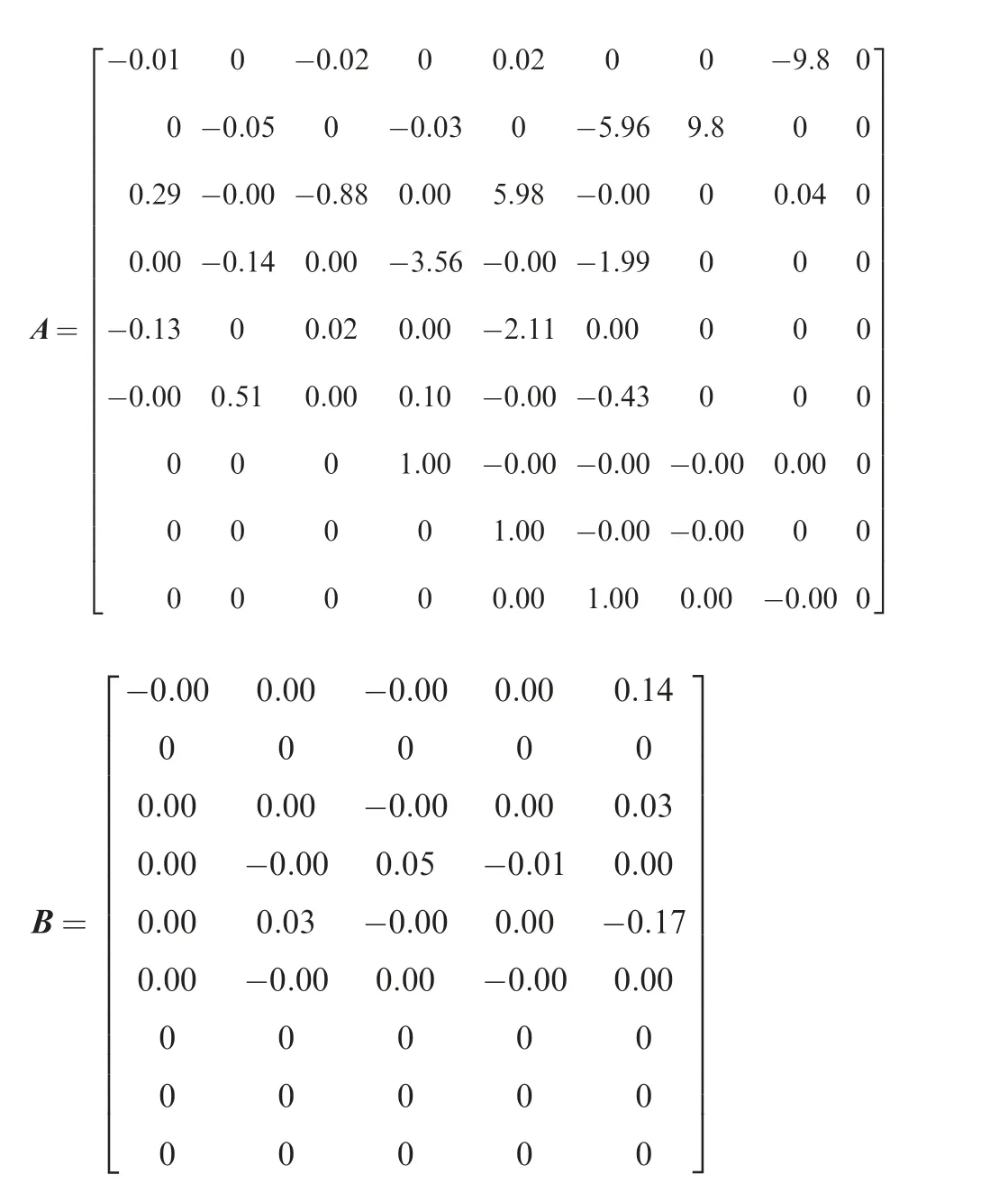
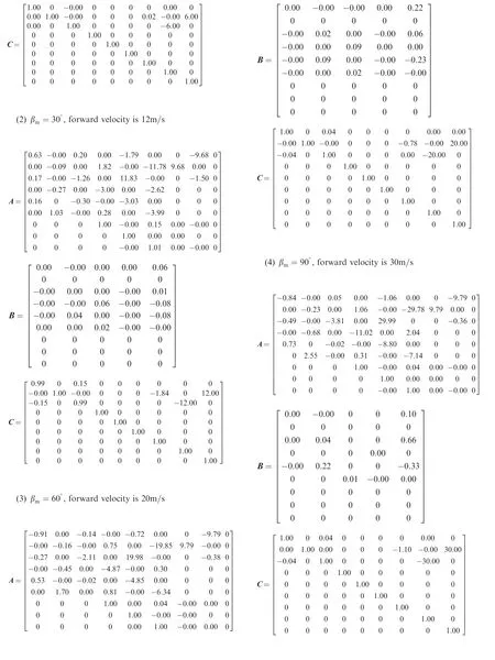
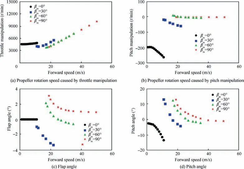
Fig. A1 Trimming result of tilt quad rotor in transition process with different forward speeds.
A.2 Trimming result of TQR
The trimming conditions with different forward speeds corresponding to different nacelle tilt angles in this paper are listed in Fig. A1.
 CHINESE JOURNAL OF AERONAUTICS2020年6期
- CHINESE JOURNAL OF AERONAUTICS的其它文章
- A novel variable structure multi-model approach based on error-ambiguity decomposition
- Multi-block SSD based on small object detection for UAV railway scene surveillance
- A new online modelling method for aircraft engine state space model
- Cross-sectional deformation of H96 brass double-ridged rectangular tube in rotary draw bending process with diあerent yield criteria
- Application of a PCA-DBN-based surrogate model to robust aerodynamic design optimization
- Numerical exploration on the thermal invasion characteristics of two typical gap-cavity structures subjected to hypersonic airflow
