An Efficient Approach for The Evaluation of Generalized Force Derivatives by Means of Lie Group
Kun Yang and Wenyu Yang
1 Introduction
Industrial robots are indispensable for reducing manufacturing costs and improving production flexibility in automated production lines. The productivity of these industrial processes is closely related to the time required to accomplish assigned tasks. However, as robot manipulators are highly nonlinear, coupled multivariable systems with nonlinear constraints, it’s difficult to make an optimal control in a direct way. Instead, the optimal control problem is solved by the trajectory planning and optimization, which can be divided into two steps: optimal trajectory planning for offline processing and corresponding online trajectory tracking[1]. Therefore, to improve the efficiency and performance of the industrial robot, the trajectory planning has become a highly interesting topic in recent researches.
The aim of trajectory planning is to generate an optimal robot trajectory from a given path considering kinematic and dynamic constraints. In the earlier study, a nonlinear programming method was proposed by Lin et al.[2]to deal with the problem of the trajectory planning. Whereas, it suffers from the deficiency that the manipulator’s dynamic performance is not considered in the trajectory planning. In this case, robot’s joint actuators are likely to be underutilized. Thus, Tan et al.[3]introduced the constraint of joint torque to make the minimum time trajectory. Manipulator’s joint forces and torques, namely the generalized forces (GFs), are naturally bounded due to the actuator’s physical limits. To make full use of capabilities of robot joint actuators, the bounding of GFs is considered in the offline trajectory planning[4]and online trajectory planning[5-9].
What’more, to prevent excessive mechanism wear, the necessity of limiting derivatives of generalized forces and torques (GFDs) can’t be neglected in the actual industrial application[10,11]. Meanwhile, some researches[12,13]pointed out that the limitation of GFDs results in smooth actuator loads so that it can improve the tracking accuracy, as well as the actuator’s life. However, there exist few researches considering constraints of GFDs in the trajectory planning because of the computational burden: it requires deducing higher derivatives of robot’s dynamic equations to evaluate GFDs. In recent years, Guarino et al.[14,15]proposed an online trajectory scaling approach that accounts for the simultaneous existence of constraints on GFs and GFDs. In this method, an efficient methodology based on Newton-Euler is proposed to calculate higher derivatives of kinematics and dynamics. As a result, the GFDs could be evaluated in a recursive way, and the computational burden has been largely reduced. According to his study, Buondonno et al.[16,17]also proposed an efficient recursive approach to deduce higher order kinematics and dynamics, so as to deal with the elastic joint in the inverse dynamic analysis.
Common to these methods on the evaluation of GFDs is the use of Denavit-Hartenberg (DH) technique. Although the evaluation is expressed in a closed-form, the formulation for higher kinematics and dynamics based on DH technique is still complex and difficult to apply: the DH technique requires local coordinates in each joint, and it’s complex to obtain the corresponding geometric parameters. Rather, it requires repetitive coordinate transformation and cross operation to deduce derivatives of kinematics and dynamics.
Instead of the general DH technique, the Lie group formulations for robot kinematics and dynamics have attracted widespread attention in recent years[18-20]. The appealing feature of this method is the frame invariance and compact representation of kinematics and dynamics. By using the Lie group, the formulation permits a high-level, coordinate-free view of robot dynamics that shows explicitly some of the connections with the larger body of work in mathematics and physics[18]. One of the strengths of the Lie group for the dynamics formulation is the ability to easily differentiate kinematics and dynamics with respect to parameters of interest.
Inspired by Guarino’s recursive method, the main contribution of this paper is to propose a more efficient approach for the evaluation of GFDs based on the Lie group theory. In particular, high-order kinematics and dynamics are deduced by means of an algorithm obtained through adding new equations to the recursive dynamic model which is originally proposed in [18]. Compared to the DH technique in Guarino method, the advantage of the proposed method is threefold. First, the Lie group uses the twist to describe linear and angular quantities (velocity, acceleration and force), simplifying the corresponding formulation of kinematics and dynamics. Second, kinematics and dynamics are described by the exponential operation. Thus, it’s convenient to deduce higher-order kinematics and dynamics for the evaluation of GFDs. Third, with the compact representation and exponential operation, the computational burden for the evaluation of GFs and GFDs is much lower than that of the DH technique, and it’s more suitable to be used in online trajectory planning application.
The paper is organized as follows. The background of the Lie group for robot kinematics and dynamics is presented in Section 2. The recursive method for the evaluation of GFDs is proposed in Section 3, while Section 4 demonstrates the detail formulation of the high-order kinematic and dynamic equations. Meanwhile, the simulation and discussion is given in Section 5, where an industrial serial robot HH-150 is used to validate the proposed method. Finally, some conclusions are reported in Section 6.
2 Geometric Background
This section presents the kinematic and recursive dynamic formulations for the serial industrial robot based on the Lie group techniques. We begin with a brief view of the geometric notation of the Lie group[21], and then follow by the recursive dynamic formulation as the traditional Newton-Euler equation[18].
2.1 Lie group SE(3) and Lie algebra se(3)
Usually, the base frame is attached to the base link of the robot, and the tool frame is fixed on the end-effector. The pose of the tool frame relative to the base frame can be expressed by a homogeneous matrix. And all of these matrices form a Lie group, representing the rigid body motion[22]. The element of such group is denoted as:
(1)
whereR∈SO(3) represents a 3×3 rotation matrix, andb∈R3.
For the industrial serial robot, we associate a twist with each revolute joint, and the corresponding twist coordinate expressed in the reference frame is defined as:

(2)
Here,w=[wx,wy,wz] represents the unit vector along the joint axis, expressed in the reference frame, andpis a position vector locating any point on the joint axis, expressed in the reference frame.
(3)
where the operation ∧ is defined as:
(4)
Meanwhile, the element of thegcan also be obtained by the exponential map exp:se(3)→SE(3). And the detail relations are derived by the following closed-form formula.

b=(e3-R)(w×υ)+θwwTυ
(5)
2.2 Adjoint mapping of SE(3) and se(3)

(6)
then, the relationship between these two corresponding twist coordinates could be obtained using the adjoint mappingAdg:se(3)→se(3).
ξa=Adg(ξb)
(7)
Similarly, the element ofse(3) can also be identified with a linear mapping via a Lie bracketadξ:se(3)→se(3), which is defined as
(8)

(9)
(10)

(11)
(12)
2.3 Recursive formulations of robot dynamics
By using the theory of the Lie group, Park et al.[18]developed a recursive formulation of rigid robot dynamics based on the standard Newton-Euler algorithm: in the forward iteration, the generalized velocities and accelerations of each link are propagated from the base to the tip. In the backward iteration, the generalized forces are propagated backward from the tip to the base. In order to better describe the formulation, some basic notations are adopted as follows.


•Airepresents the six-dimensional generalized acceleration of the linkiframe, expressed in linkiframe coordinates
•Gi∈R6×6is the generalized inertial matrix of linkidefined as
(13)
where (1)iIirepresents the inertial matrix of linkiabout center of mass, relative to a frame at the center of mass that is parallel to the linkiframe. (2)miis the mass of the linki. (3)riis the vector from the origin of the linkiframe to the center of mass linki, expressed in linkiframe coordinates.
•Firepresents the six-dimensional generalized force transmitted from linki-1 to linkithrough jointi, expressed in the linkicoordinate, and the first three components ofFiis the moment vector.
•τirepresents the joint torque of actuatori.

With these notations, the recursive formulation of the robot inverse dynamics can be computed as follows.
• Forward recursion: fori=1,2,…,n
(14)
(15)
• Backward recursion: fori=n,n-1…1
(16)
(17)
3 Efficient Approach for The Evaluation of GFDs
The recursive approach based on the Lie group in this section efficiently evaluates the joint GFDs for rigid, open-chain manipulators. As usual, it returns the solution of the inverse dynamic problem given by

(18)
Because of the good characteristics of the exponential operation for differentiation, the Lie group can be used to evaluate GFDs by differentiating the dynamic equation (18).

(19)
In this way, the new efficient approach is implemented to traditional dynamic equation by adding new expressions. For each link of the manipulator, the forward recursion returns generalized velocities, accelerations and jerks. And the backward recursive formulation gives the solution of the inverse dynamic problem by evaluating GFs and GFDs of each link. The efficient algorithm for the evaluation of GFs, especial GFDs is proposed in the following subsections, while its high-order kinematic and dynamic equations are deduced in Section 4.
3.1 Forward recursion
The following recursive algorithm evaluates the generalized velocities, accelerations and jerks of each link (i=1,2,…,n):
(20)
(21)
(22)
where,Jithe six-dimensional generalized jerk of framei.
3.2 Backward recursion
With the serial manipulator kinematics and corresponding derivatives in (20)-(22), it’s possible to evaluate joint GFs and GFDs from the knowledge of the external forces acting on each link. And the recursive formulation is proposed as follows (i=n,n-1…1):

(23)

(24)
(25)
(26)

Fig.1 shows that, with the given trajectory, GFs and GFDs can be evaluated efficiently in a programmable way. Actually, the accuracy of the evaluation for the GFs and GFDs can be improved by considering the friction and motor inertial. The influence of these two factors on the joint torque can be derived according to [23]. Just as the study of Guarino, it’s possible to get the more accurate evaluation by adding the derivatives of GF components corresponding to friction and motor inertial. In this study, both influences of these two factors are neglected for the sake of simplicity.
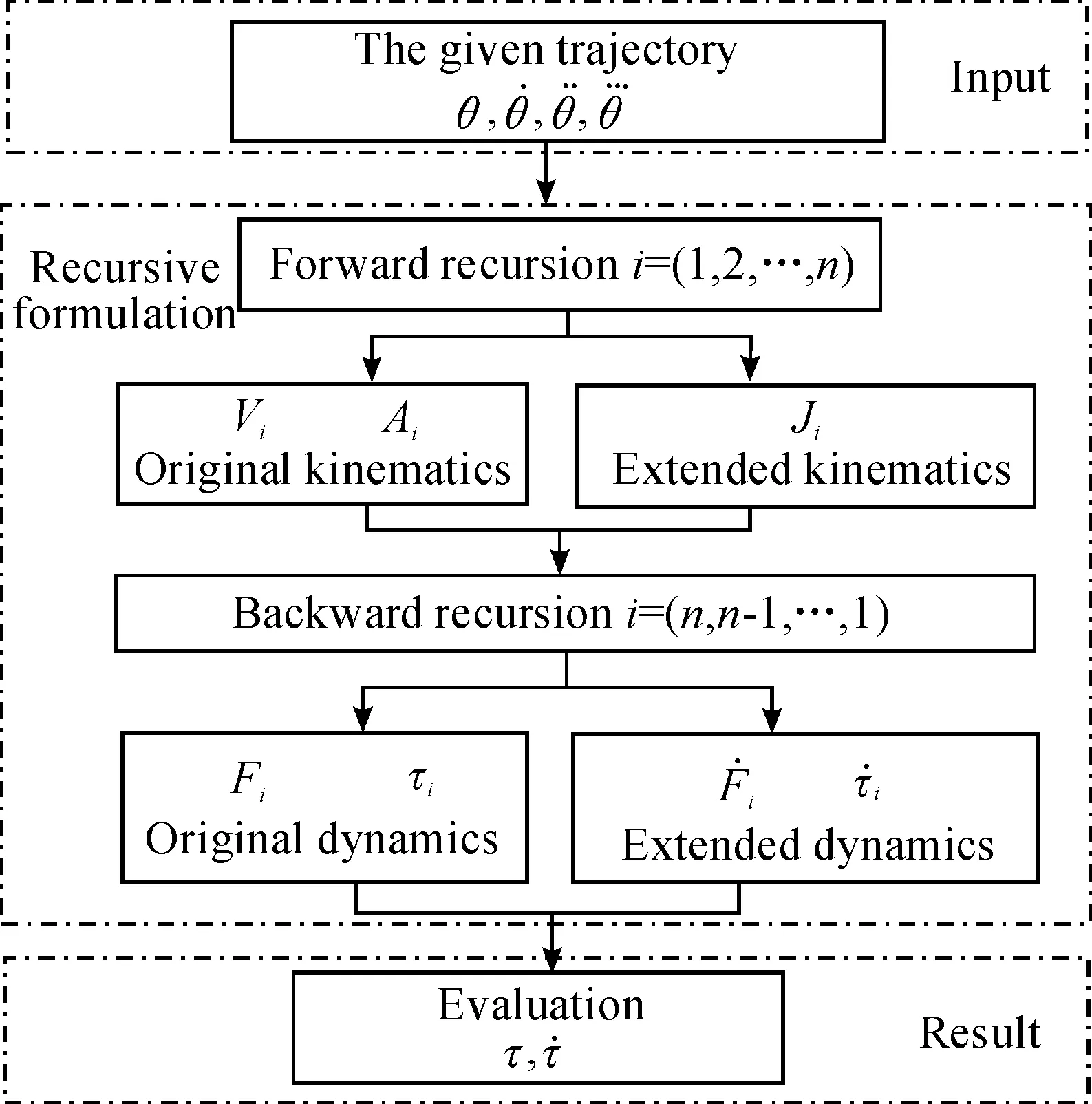
Fig.1 The flowchart of the proposed method for the evaluation of GFs and GFDs.
4 Synthesis of Recursive Equations
The efficient approach for the evaluation of the GFs and GFDs based on the Lie group is given in equations (20)-(26). And detail formulations of these equations are deduced in this section.
4.1 Recursive formulation of high-order kinematics

(27)
Substituting (27) and (20) into (15), the final generalized acceleration can be rewritten as
(28)

(29)

(30)
By taking into account (8) and (27), the derivative ofξcican be obtained by
(31)
Thus, the second-order derivative of the generalized velocity (the generalized jerk) is written as
(32)
4.2 Recursive formulation of high-order dynamics

(33)

(34)
Substituting (34) into (33), we can get
(35)
Therefore, the derivative of generalized forces is written as

(36)
5 Simulation and Discussion
In order to validate the effectiveness of the proposed method for the evaluation of GFDs, a simulation is conducted on an industrial robot HH-150 (self-developed by Huaheng Weld Co., Ltd), whose kinematic and dynamic parameters are shown in Table 1 and 2, respectively. And the trajectory of each joint for the simulation is given in Table 3.
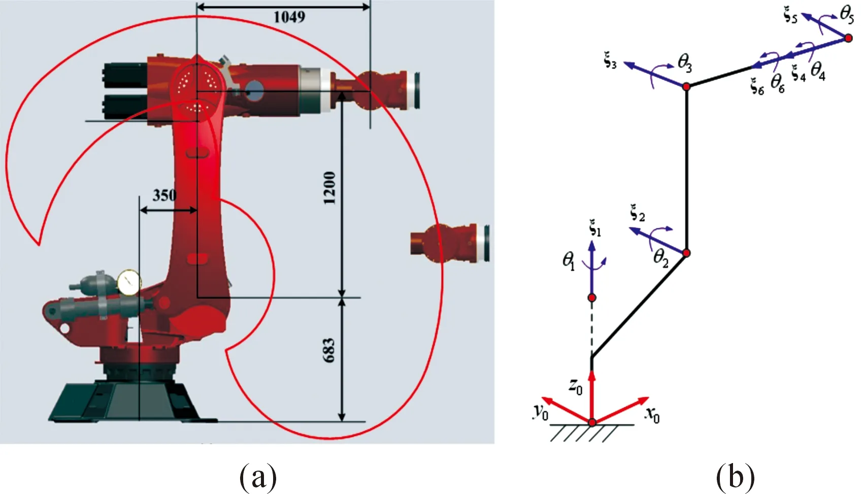
Fig.2 The joint coordinate system of HH-150 robot.

Table 2 Dynamic parameters of HH-150 robot.
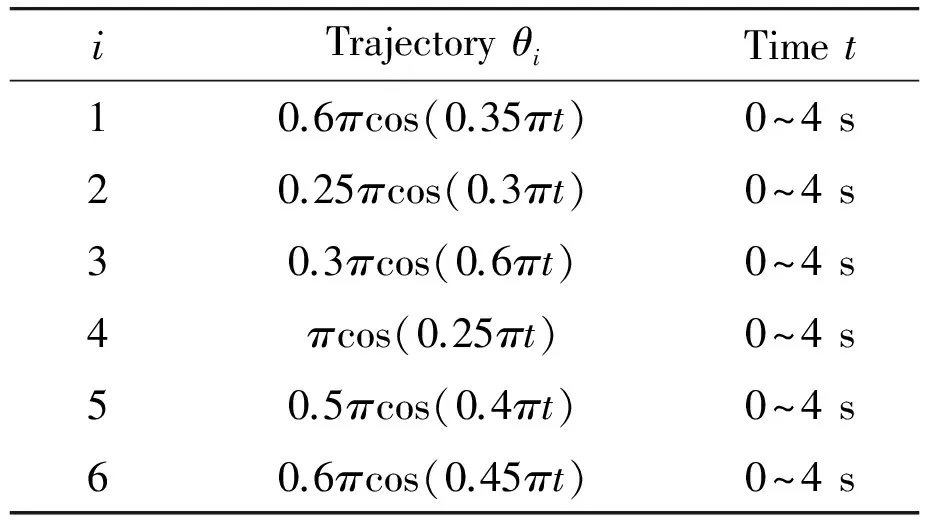
Table 3 The trajectory of each joint.
Firstly, we compare the proposed method with the commercial dynamic software (Adams) for the evaluation of GFs. As shown in Fig.3, GFs obtained from the proposed method match well with those calculated by the classical dynamic software Adams. Subsequently, GFDs are evaluated according to the proposed method (20)-(26). To further validate the correctness of the proposed method, the evaluation of GFDs is also derived by the existed Guarino method[14]. Fig.4 shows the comparison between the proposed method and Guarino method. It can be observed that these two methods have well in agreement with each other for the evaluation of GFDs. In this way, the proposed method based on the Lie group is shown to be able to evaluate the GFs and GFDs accurately in a closed-form.
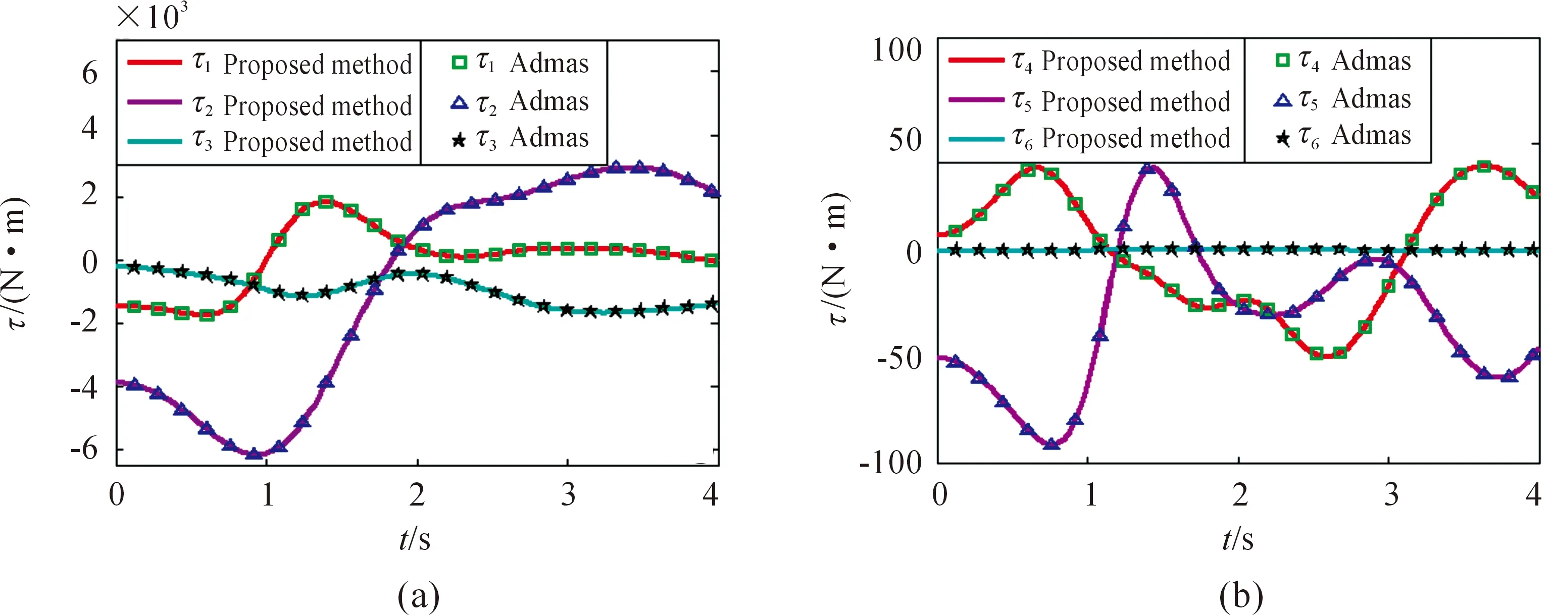
Fig.3 Comparisons of the GFs between the proposed method and Adams (a) GFs of the first three joint and (b) GFs of the last three joint.
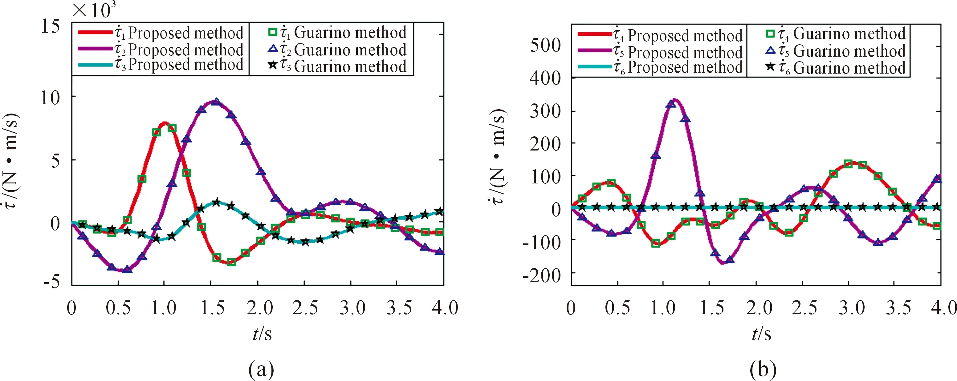
Fig. 4 Comparisons of the GFDs between the proposed method and Guarino method (a) GFDs of the first three joint and (b) GFDs of the last three joint.

Likewise, the computational time for GFDs evaluation is also obtained by the Guarino’s method under the same simulation environment. And the comparison about the efficiency is described in Table 4. It’s noteworthy that the proposed method based on the Lie group is more efficient than the existed method using the DH technique. Especially for the evaluation of GFDs, the efficiency has been largely improved largely by the Lie group technique. This can be explained in the following reasons: (1) due to characteristics of the exponential operation, it’s easier to get the derivatives based on the Lie group than the classical DH method; (2) the Lie group technique uses the twist to describe the generalized velocity and force, making the formulation more concisely: the proposed method only needs 4 expressions (14)-(17) to describe the recursive dynamic model, compared to 9 expressions in the classical Newton-Euler method[24]. Then, the difference of the corresponding derivatives between two methods becomes larger with the increase of the manipulator’s freedom. As a result, the computational burden for the evaluation of GFDs is bigger in the Guarino method, compared to the proposed method based on the Lie group.
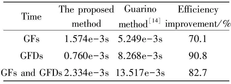
Table 4 The computational time for the evaluation of GFS and GFDS.
Therefore, with the comparison of these two methods, the proposed method is able to evaluate the GFs and GFDs. What’s more, the proposed evaluation method has largely improved the efficiency for the evaluation of GFs and GFDs, and it’s more suitable for the online applications.
6 Conclusion
To fully utilize the joint actuators in the trajectory planning, a more efficient and accurate method is proposed to evaluate GFs and GFDs in this paper. Compared to the existed DH method, the proposed method based on the Lie group is more efficient and concise, especially when the freedom of the manipulator becomes larger. The exponential operation makes the Lie group easier to compute derivatives of manipulator’s kinematics and dynamics. Thus, the accuracy and computational burden can be largely improved by using iterative closed-form expressions instead of approximated numerical differentiation methods. One important application of this approach is that the proposed method for the evaluation of GFs and GFDs can be used as online trajectory planning for the complex manipulator. Further, the high-order kinematics and dynamics based on the Lie group can be used to analysis the dynamics of the manipulator with elastic joints.
Acknowledgement
This work is supported by the Major State Basic Research Development Program of China (973 Program, Grant No. 2014CB046704), National Science and Technology Support Plan (Grant No. 2014BAB13B01).
[1]A.Piazzi and A.Visioli, Global minimum-jerk trajectory planning of robot manipulators,IEEETrans.Ind.Electron., vol.47, no.1, pp.140-149, 2000.
[2]C.Lin, P.Chang and J.Luh, Formulation and optimization of cubic polynomial joint trajectories for industrial robots,IEEETrans.Autom.Control., vol.AC-28, no.12, pp.1066-1074, 1983.
[3]H.H.Tan and R.B.Potts, Minimum time trajectory planner for the discrete dynamic robot model with dynamic constraints,IEEEJ.Robot.Autom., vol.4, no.2, pp.174-185, 1983.
[4]L.Zlajpah, On time optimal path control of manipulators with bounded joint velocities and torques, inProc.Int.Conf.Robot.Autom., Minneapolis, Minnesota, 1996, pp.1572-1577.
[5]O.Dahl and L.Nielsen, Torque-limited path following by online trajectory time scaling,IEEETrans.Robot.Autom., vol.6, no.5, pp.554-561, 1990.
[6]W.S.Owen, E.A.Croft and B.Benhabib, Real-time trajectory resolution for a two-manipulator machining system,J.Robot.Syst., vol.22, no.S1, pp.S51-S63, 2006.
[7]J.Moreno-Valenzuela and E.Orozco-Manríquez, A new approach to motion control of torque-constrained manipulators by using time-scaling of reference trajectories,J.Mech.Sci.Technol., vol.23, no.12, pp.3221-3231, 2009.
[8]O.Gerelli and C.G.L.Bianco, Nonlinear variable structure filter for the online trajectory scaling,IEEETrans.Ind.Electron., vol.56, no.10, pp.3921-3930, 2009.
[9]F.Debrouwere, W.V.Loock, G.Pipeleers, Q.T.Dinh, M.Diehl, J.D.Schutter, and J.Swevers, Time-Optimal Path Following for Robots With Convex-Concave Constraints Using Sequential Convex Programming,IEEETrans.Robot., vol.29, no.6, pp.1485-1495, 2009.
[10] K.Shin and N.McKay, A dynamic programming approach to trajectory planning of robotic manipulators,IEEETrans.Autom.Control, vol.AC-31, no.6, pp.491-500, 1986.
[11] D.Costantinescu and E.A.Croft, Smooth and time-optimal trajectory planning for industrial manipulators along specified paths,J.Robot.Syst., vol.17, no.5, pp.233-249, 2000.
[12] S.Macfarlane and E.A.Croft, Jerk-bounded manipulator trajectory planning: design for real-time applications,IEEETrans.Robot.Autom., vol.19, no.1, pp.42-52, 2003.
[13] S.Perri, C.G.L.Bianco and M.Locatelli, Jerk bounded velocity planner for the online management of autonomous vehicles,IEEEInt.Conf.Autom., Gothenburg, Sweden, 2015, pp.24-28.
[14] C.G.L.Bianco, Evaluation of generalized force derivatives by means of a recursive Newton-Euler approach,IEEETrans.Robot., vol.25, no.4, pp.954-959, 2009.
[15] C.G.L.Bianco and O.Gerelli, Online Trajectory Scaling for Manipulators Subject to High-Order Kinematic and Dynamic Constraints,IEEETrans.Robot., vol.27, no.6, pp.1144-1152, 2011.
[16] G.Buondonno and A.De Luca, A recursive Newton-Euler algorithm for robots with elastic joints and its application to control,IEEEInt.Conf.Robot.Sys., 2015, pp.5526-5532.
[17] G.Buondonno and A.De Luca, Efficient Computation of Inverse Dynamics and Feedback Linearization for VSA-Based Robots,IEEERobot.Autom., vol.12, no.1, pp.908-915, 2016.
[18] F.C.Park, J.E.Bobrow and S.R.Ploen, A Lie group formulation of robot dynamics,Int.J.Robot.Res., vol.14, no.6, pp.609-618, 1995.
[19] C.Li, POE-Based Robot Kinematic Calibration Using Axis Configuration Space and the Adjoint Error Model,IEEETrans.Robot., vol.26, no.5, pp.1264-1279, 2016.
[20] A.Müller, Screw and Lie group theory in multibody kinematics,MultibodySystDyn, 2017.
[21] J.Selig,GeometricFundamentalsofRobotics.New York: Springer-Verlag, 2005.
[22] X.Yang, A minimal kinematic model for serial robot calibration using POE formula,Robot.Comput.Integr.Manuf., vol.30, no.3, pp.326-334, 2014.
[23] L.Sciavicco and B.Siciliano,ModelingandControlofRobotManipulators. New York: Springer-Verlag, 2012.
[24] J.J.Craig,Introductiontorobotics:mechanicsandcontrol(Vol.3). Upper Saddle River: Pearson Prentice Hall, 2005.
Appendix
We derive here the formulation of the recursive dynamics presented in Section 2. Firstly, the forward iteration of generalized velocities and accelerations are deduced. Let the transformation from frameito framei-1 be given by
(1)
It’s trivial to get the relationship between the transformation matrix and corresponding derivative.
(2)
Meanwhile, the six-dimensional generalized velocityVi(expressed in linkiframe coordinates) of the linkiframe can be expressed by the transformation matrixgi(the linkireference frame relative to the inertial frame).
(3)
Thus, the six-dimensional generalized velocityVican be expressed as
(4)

(5)
Then, the six-dimensional generalized accelerationAiis expressed as
(6)
Secondly, the forward iteration of generalized forces is deduced as follows. According to the standard equations of motion for the rigid body, the resultant force and moment applied on each linkiare
(7)
where
(8)
Note that the above three-dimensional vectors are all expressed in terms of local frame coordinates:vi= velocity of linkiframe,ωi= angular velocity of linkiframe,aci= acceleration of linkicenter of mass,Ti= resultant moment about the origin of the linkiframe,fi= resultant force applied to linki.
Then, combining with equation (8), the resultant force and moment applied to linkican be rewritten as
(9)
In addition, the six-dimensional generalized velocity and acceleration are equivalent to
(10)
Considering characteristics of the cross-product and adjoint mapping, the three-dimensional force and moment applied to linkiare
(11)


(12)
Namely,

(13)
 CAAI Transactions on Intelligence Technology2017年4期
- CAAI Transactions on Intelligence Technology的其它文章
- Magnetic Orientation System Based on Magnetometer, Accelerometer and Gyroscope
- A Mixed Reality System for Industrial Environment: an Evaluation Study
- Diagnosis System for Parkinson’s Disease Using Speech Characteristics of Patients and Deep Belief Network
- Visual Navigation Method for Indoor Mobile Robot Based on Extended BoW Model
- Proposal of Initiative Service Model for Service Robot
- A Lane Detection Algorithm Based on Temporal-Spatial Information Matching and Fusion
