Magnetic Orientation System Based on Magnetometer, Accelerometer and Gyroscope
Zhiwei Chu, Chilai Chen, Youjiang Liu, Yingxian Wang, and Xinhua Lin
1 Introduction
The magnetic azimuth is the angle relative to the orientation of the earth magnetic field component in the horizontal plane, indicating the knowledge of the horizontal or vertical plane must be required to correct the measured magnetic value in the application of magnetic orientation systems. The tilt angles are commonly obtained by measuring the gravity vector at rest. In the previous report[1], it has been shown that the azimuth derived from the values of magnetometers and tilt contains and propagates the errors present in the attitude angles themselves. Thus, the orientation precision of magnetic orientation systems not only depends on the calibration validity of magnetometers, but also was closely related to the errors of tilt angles.
Usually, accelerometers are used to compensate for the azimuth by achieving attitude angles information[2-8]. In these references, the magnetic orientation systems have high precision partly because they are working in static state. However, when the magnetic orientation system works in dynamical state, the acceleration field obtained from the accelerometers contains kinematic acceleration besides gravitational acceleration. Thus, the real dynamic attitude of magnetic orientation systems can’t be resolved from the output of accelerometers. As a result, just based on the data of magnetometers and accelerometers the azimuth error of magnetic orientation systems will be enlarged in the case of movement. Especially, when the kinematic acceleration disturbance is violent, the magnetic orientation systems will lose its functionality.
To deal with this problem, gyroscopes are introduced into magnetic orientation systems[10-12, 15]. These studies mainly focus on the sensor fusion algorithms and less analysis is applied to the calibration of sensors. However, the large measurement error in the output of sensors will lead to the large error of the data fusion results and poor convergence ability. Thus, at first magnetometer, accelerator and gyroscope in magnetic orientation system must be calibrated in order to obtain the actual real-time azimuth and attitude through the data fusion algorithm. Complementary filter (CF) algorithm is widely used in the field of unmanned aerial vehicles (UAV) and micro aerial vehicles (MAV). For the CF, a set of attitude angles are estimated in each measurement and they are multiplied with the corresponding gain factors. The eventual attitude angles are the sum of the parts. The more accurate estimations can be made by adjusting the gain factors. CF can be realized easily, but its accuracy is relatively low. It is only suitable for the low-dynamic application due to its slow response[16-18, 20]. The quaternion based extended Kalman filter (EKF) is appropriate for non-linear plant models. Among the variants of the Kalman filtering framework, EKF is the most prominent one for its relatively high accuracy. However, in this algorithm the magnetic measurement is fused into roll and pitch, resulting in the larger error of yaw and the low precision in the pitch and roll angles once magnetic interference occurs[10, 18, 19, 21]. In addition, Jacobi matrix needs to be calculated in EKF, which will introduce the linearization error inevitably.
Based on the previous studies of the tri-axis magnetometer calibration with error-separation method[8], the tri-axis accelerometer calibration with multi-position method[5, 6]and the tri-axis gyroscope calibration through the method of three-position with six different angular velocities[9], a quaternion based Kalman filter (KF) is proposed in this paper to fuse the data from sensors and to estimate the orientation. In the measurement model, the state vector of quaternion is converted from the Euler angles which are resolved from the output of accelerometer and magnetometers instead of the accelerometer and magnetometers measurement vectors which are used in the traditional method of EKF[19]. So we can apply KF to the system without calculating Jacobi matrix since the process model and the measurement model are linear, which means no linearization error, lower cost of computation and less computational time. Better yet, when magnetic disturbances are present their influence is only limited to the heading angle. The achievement of the high-precise magnetic orientation system which can work well under various operation conditions demonstrated that the calibration and data fusion algorithm of multi-sensors are effective. And, the magnetic orientation system is suited to the practical application since it is composed of commercial-off-the-shelf components.
2 The Principle of Magnetic Orientation System without Gyroscope
The case body frame of magnetic orientation system is denoted as thebcoordinate frame and has three orthogonal axes ofxb,ybandzb. We define thatxl,ylandzlare the axes of the local horizontal frame (l). Thexlis along the direction of horizontal projection ofxb,zlis along the downward direction, andxl,ylandzlobey the right-hand rule.
So, ifθdenotes the pitch angle of the vehicle andφdenotes roll angle of the vehicle, the components of Earth magnetic field in thexlandyldirection can be calculated as follows:


(1)
The magnetic headingψis obtained by the following formula:
(2)
(3)
Simplifying (3) and taking into account that:
(4)
whereδis the inclination of the magnetic vector andHhthe horizontal magnetic field. The error produced can be written as:
Δψ=-Δθ·tanδ·cosψ-Δφ·tanδ·sinψ
(5)

3 Calibration of Sensors
The magnetic orientation system we developed comprises with three single axis magnetometers, a tri-axis accelerometer, and a tri-axis gyroscope. The calibration methods of sensors will be introduced as follows.
3.1 Calibration of three single axis magnetometers
According to Eq. (2), the absolute magnitude ofhi(i=x,y,z) is not necessary to compute the magnetic heading. In this paper, the error-separation method[8]is adopted to calibrate the magnetometers in consideration that it is convenient to evaluate the influence of different error sources and to get high precision of measurement. The output model of magnetometers can be expressed as follows:
(6)
At the right side of Eq. (6), the first diagonal matrix accounts for the different sensitivities of the magnetometers, the second 3×3 matrix represents the output influence from non-orthogonality and misalignment of the three magnetometers, and the bias is embodied in the matrix aboutb.
With the three-axis non-magnetic rotation platform, the parameters in Eq. (6) can be obtained, so the errors from the sensitivity inconsistency, the non-orthogonality and misalignment and the combined biases can be eliminated independently. Now we get the output components of earth magnetic field in the body frame as follows:
(7)
Finally, the magnetic heading can be calculated by above Eqs. (1) and (2). After the calibration of magnetometers is accomplished, the relevant parameters are also acquired. The angles between the axes in the measurement frame and the body frame are shown in Table 1. The characteristic curves of magnetometers acquired with a linear least squares fit are shown in Fig.1. According to the fitted curves, the parameters in the calibration matrix could be obtained. The result is shown as follows:
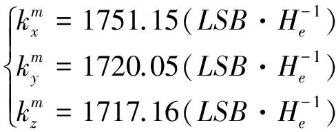
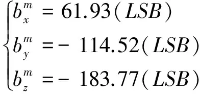
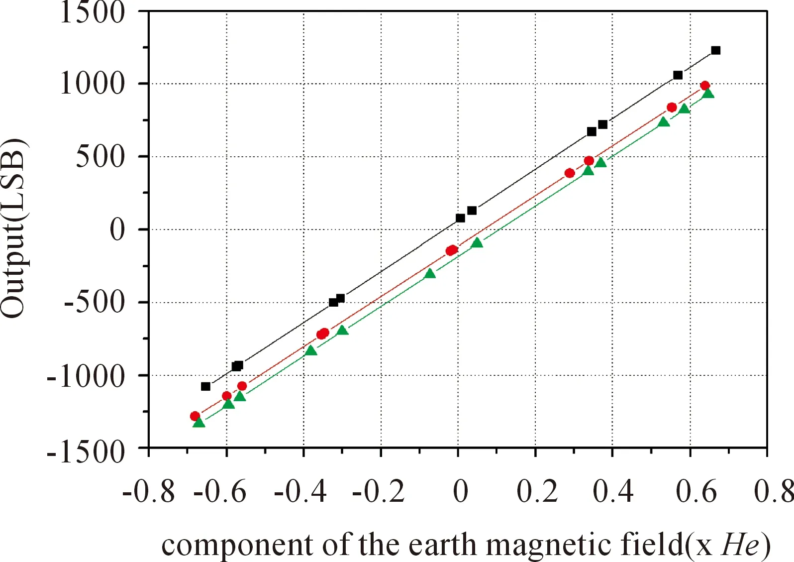
Fig.1 Fitted curves between the outputs of magnetometers and the component of the earth magnetic field in the direction of the magnetic sensor axes (xmaxis: —, ymaxis: — and zm axis: — ) and the original outputs of magnetometers (xmaxis:■, ymaxis: ● and zmaxis: ▲); He is equal to the magnitude of the earth magnetic field.
Now all the parameters to calibrate the magnetometers have been obtained. And if the true pitch angle and roll angle (as in static state) are known, we can determine orientation of the vehicle precisely with equations (1) and (2).
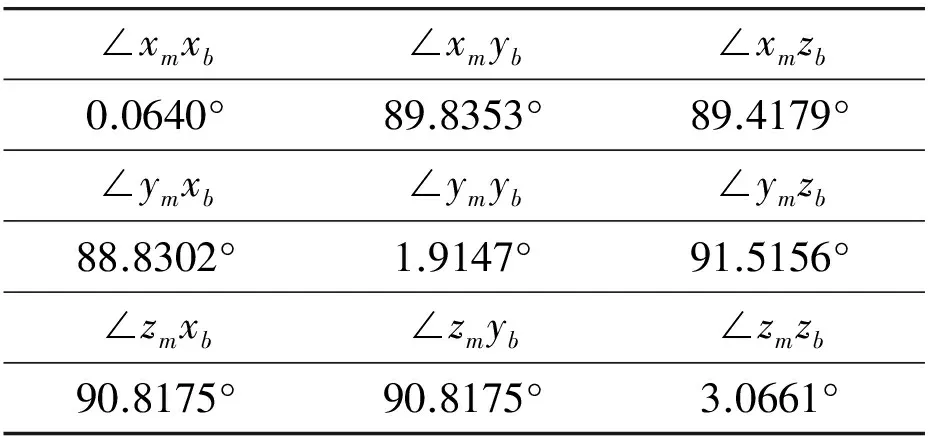
Table 1 Angles between the axes in the measurement frame and the body frame.
3.2 Calibration of tri-axis accelerometer
Unlike magnetometer, the accelerometer is immune to environmental impact because the gravity vector stays almost unchanged wherever it works. There are lots of methods to calibrate the tri-axis accelerometer. The so-called multiposition calibration is used mostly hitherto and has been proved to be effective[5,6].
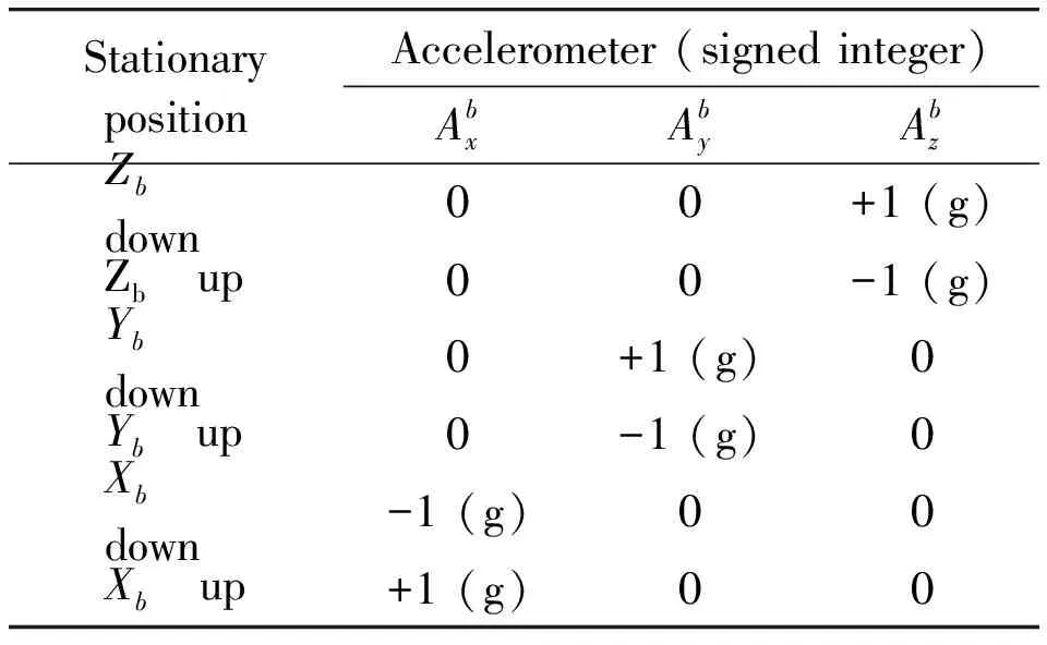
Table 2 Sign definition of the tri-axis accelerometer raw measurements.

(8)
where[A_m]3×3is the 3×3 matrix representing the misalignment between the accelerometer sensing axes and the device body axes.A_Si(i=x,yorz) is the sensitivity andA_Oi(i=x,yorz) is the offset.
Then, the pitch and roll angles of device can be calculated as the following:
(9)
(10)


(11)
According to the above equations (8-10), we need 12 parameters fromA10toA33to calibrate the tri-axis accelerometer. By mounting the magnetic orientation system on the 3-D rotation platform which has a high-precision digital encoder, calibration can be operated at 6 stationary positions as shown in Table 2. We collect at least 100 sets of data at each position and take the averages. The 12 desired coefficients are extracted from the obtained data by the least square method as shown in Table 3.
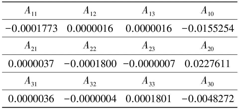
Table 3 Coefficients of calibration for the tri-axis accelerometer.
3.3 Calibration of tri-axis gyroscope
Tri-axis gyroscope works by sensing angular velocity around the three sensitive axes. However, to ensure high precision, tri-axis gyroscope must be calibrated before use[9].
The output model of the tri-axis gyroscope can be expressed in a matrix form as follows:
(12)

The 12 parameters about k can be calculated with least square method as follows:

(13)
(14)
(15)
(16)

After the processing of calibration, the matrix K is listed as follows:

(17)
4 Data Fusion
In order to diminish the influence of non-gravitational acceleration, after the above calibrations, the data obtained from the sensors are further combined based on Kalman filtering with a state vector consisting of four elements (the quaternion components), a linear process model and a linear measurement model. The quaternion converted from Euler angles (computed with the Eqs. (2), (9) and (10)) is taken as the measurement for the Kalman filter to correct the predicted state obtained by processing the readings provided by the angular rate sensor (the tri-axis gyroscope). Using this method, all the output equations are linear, which simplifies the design of the filter, and the nonlinear error from EKF can be eliminated.
4.1 Process model
In the prediction step, the angular velocity vector, measured by the tri-axis gyroscope, is used to compute the first estimation of the orientation in quaternion form. It is well known that the rigid body angular motion obeys a vector differential equation[10,11]describing the rate of change of the orientation as quaternion derivative:
(18)
where
(19)
(20)

(21)
represents the standard vector cross-product[11].
In this paper, quaternion represents the notation from:
(22)
whereq1,q2,q3andq4are real numbers andi,j, andkare unit vectors directed along thex,y, andzaxis respectively. A quaternion is unit quaternion[12]if:
The direct cosine matrix given in terms of the orientation quaternion can be expressed as the following matrix:
(23)
Thus, we can establish the process model as the following:

(24)
wherekis the sampling number, dtis the sampling period, and

(25)


(26)
4.2 Measurement model
After calibration, the Euler angles can be computed with equations (2), (6) and (7) according to the output of the accelerometer and the magnetometers. The quaternion converted from the Euler angles is used in the measurement update step. The transformation formula is expressed in the reference[13]:
(27)
wherecφ=cos(φ/2),sφ=sin(φ/2),θis pitch angle,φis roll angle, andψis heading angle (computed with Eqs. (2), (6) and (7)). The measurement model can be expressed as the following equation:
Z(k)=q(k)+ξ(k)
(28)
whereξ(k) is the measurement noise which is approximated as a white Gaussian noise obtained from the propagation of the acceleration and magnetic field measurement noise[14]. The measurement noise covariance matrix isRk.
4.3 Kalman filter
As a recursive estimator, the following formulas are used in computation:


(29)

(30)
5 Experimental Results
For verification of the calibration methods and the proposed algorithm of data fusion, a 3-D non-magnetic platform that can rotate around three axes by manual operation was used. Before data fusion, the accuracy of error-separation calibration method in static state is shown in Fig.2 where the horizontal coordinate axis stands for platform readings. We can see that with the magnitudes of both pitch and roll angles increasing, the heading errors exhibited an increasing trend. But the maximum error in the heading was only about 0.4° even if the magnitudes of both pitch and roll angles increased up to 60°. And precision comparisons of different calibration methods are listed in Table 4. The ellipsoid fitting method and the traditional method are provided by [5] and [7]. These results demonstrated that the calibration method of error- separation was very effective and efficient.
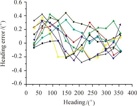
Fig.2 Heading errors of magnetic orientation system with the different attitudes, () θ=0°, γ=0°; () θ=30°, γ=30° and () θ=30°, γ=-30°; () θ=-30°, γ=30°; ()θ=-30°, γ=-30°; () θ=60°, γ=60°; () θ=60°, γ=-60°; ()θ=-60°, γ=60° and () θ=-60°, γ=-60°.
After calibrating the sensors, two modes of experiments had been carried out to evaluate accuracy of our magnetic orientation system. Mode 1 is the static state, and Mode 2 is the dynamic state. The results from the proposed Kalman filter (q-KF) are provided and for comparison, the corresponding results from EKF and CF are also shown.
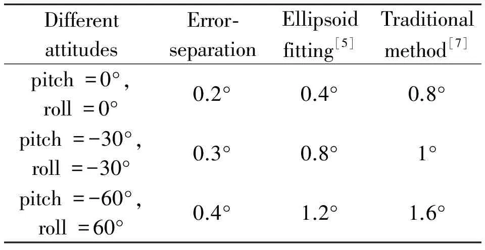
Table 4 The heading accuracies of different calibration methods in different attitudes.
In Mode 1, the magnetic orientation system was rigidly mounted on the 3-D non-magnetic platform and was kept static (remain level: true pitch and roll angles were equal 0° ) when we were collecting data outputs. The results are shown in Fig.3. The data called Measured (blue) were computed without data fusion only from the output of the tri-axis accelerometer and the magnetometers (as Eqs. (2), (9) and (10)), while the data called Estimated (green) were computed by the q-KF (as Eq. (30)). The black solid line called Reference represents the readings of the 3-D non-magnetic platform. We can see that with the Kalman filter algorithm proposed this paper, the magnetic orientation system is steadier (0.1° ) than the one without data fusion (0.4° ). And the errors of yaw, pitch, and roll angles computed by the data fusion in our magnetic orientation system are very small as about 0.1°.
In Mode 2, the magnetic orientation system was mounted on the 3-D non-magnetic platform, then we carried out two kinds of operation conditions (Mode 2 (a) and Mode 2 (b)). In Mode 2 (a), the roll angle was dynamically changed by manual operation when the pitch angle was kept at 0°. From Fig.4, it can be seen that after calibration and data fusion based on q-KF (Estimated), the maximum error of yaw angle was about 2.8° and the maximum error of pitch angle was about 0.3°. But, without the data fusion (Measured) the maximum error of yaw angle was more than 10° and the maximum error of pitch angle was about 2.5°. In Mode 2 (b), when the roll angle was kept at 0°, the pitch angle was dynamically changed by manual operation. As shown in Fig.5, with the q-KF the maximum errors of yaw and roll angles decreased from about 6.5° (Measured) to about 2.5° (Estimated) and from about 2.5° (Measured) to about 1.8° (Estimated) in Mode 2 (b), respectively. The above results demonstrate that the heading and attitude precision were improved significantly with our calibration methods and data fusion algorithm based on Kalman filter. It’s worth mentioning that since roll angle (Mode 2 (a)) and pitch angle (Mode 2 (b)) of the 3-D non-magnetic platform was changed by manual operation, their real angle values were unobservable during changing with time. Thus, the data of roll angles (Mode 2 (a)) and pitch angles (Mode 2 (b)) are not shown in this paper.
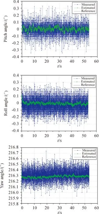
Fig.3 Test in Mode 1: Outputs of pitch, roll and yaw angles in static state.
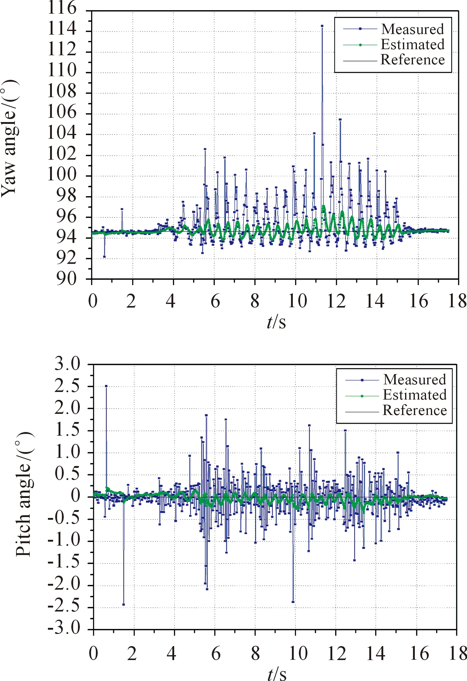
Fig.4 Test in Mode 2 (a): Outputs of yaw and pitch angles in dynamic state when roll angle was dynamically changed.
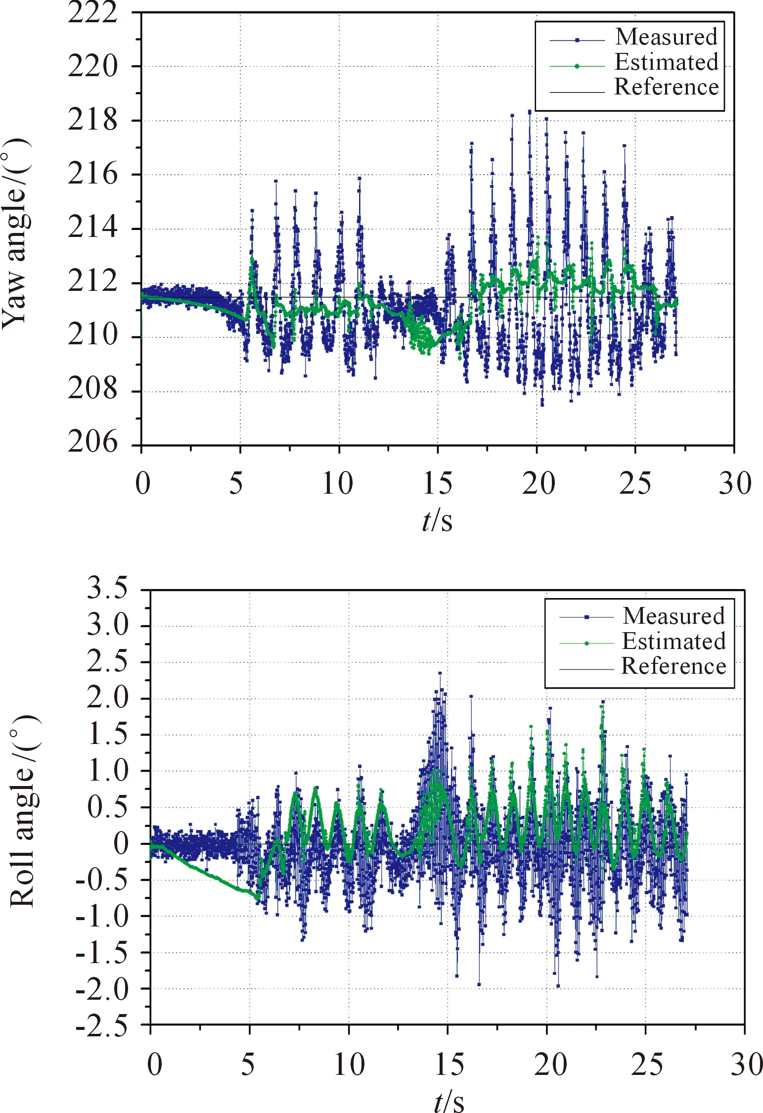
Fig.5 Test in Mode 2 (b): Outputs of yaw and roll angles in dynamic state when pitch angle was dynamically changed.
Obviously, in the dynamic circumstance the magnetic orientation system without gyroscope and data fusion is useless and the errors, especially the error of yaw angle, are large. After this magnetic orientation system was applied with our calibration methods and data fusion algorithm, the error of yaw angle was less than 3° and the attitude (pitch and roll) errors were less than 2°. At last, the precision comparisons between different data fusion algorithms are shown in Table 5. The above experimental results show that our magnetic orientation system has the good performance and practicability even in dynamic work conditions.
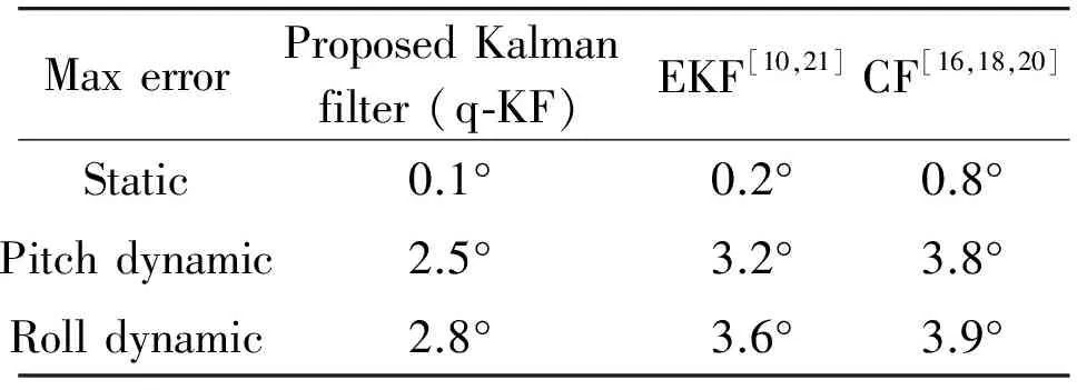
Table 5 The heading accuracies of different data fusion methods in static and dynamic state.
6 Conclusions
In this paper, the magnetic orientation system was developed with three magnetometers, a tri-axis accelerometer and a tri-axis gyroscope. Magnetometer and accelerometer were calibrated with the error-separation method and six-position method, respectively. And, the method of three-position with six different angular velocities was adopted for calibrating gyroscope. Finally, in order to keep the functionality of the magnetic orientation system in dynamic state, a data fusion algorithm base on linear Kalman filter (q-KF) was developed. The experimental results show that the accuracy of the heading and attitude was improved significantly both in static and dynamic states after the improved data fusion. The maximum error of yaw angle was about 0.1° in static state and 2.8° in dynamic state. And the maximum error of attitude (pitch/roll angle) was about 0.1° in static state and 1.8° in dynamic state. The achievement of magnetic orientation system with high precision demonstrated that the methods of calibration and the data fusion algorithm were effective and practical. It is worth mentioning that in terms of the estimation accuracy, due to the various dynamic conditions this paper does not claim that the parameters of Kalman filter are effective and suitable in any dynamic condition. In other words, the kinematic condition must be considered in term of the severity of the external accelerations in order to improve the estimation performance by adjusting the parameters of Kalman filter. Thus, a future research direction will be focused on an adaptive algorithm for learning the parameters in real time to further improve the adaptability of magnetic orientation systems.
Acknowledgment
The research is supported by National Natural Science Foundation of China (Project number: U1732152).
[1]Q.Ladetto, J.V.Seeters, S.Sokolowski S, Z.Sagan, and B.Merminod, Digital Magnetic Compass and Gyroscope for Dismounted Soldier Position & Navigation, inProceedingsofNATO-RTOMeetings, Istanbul, Turkey.2002.
[2]M.Sipos, J.Rohac, and P.Novacek, Improvement of electronic compass accuracy based on magnetometer and accelerometer calibration,ActaPhys.PolonicaA, vol.121, no.4, pp.945-949, 2012.
[4]V.Renaudin, M.H.Afzal, and L.Gérard, Complete Triaxis Magnetometer Calibration in the Magnetic Domain,JournalofSensors, vol.2010, pp.23-59, 2010.
[5]J.Fang, H.Sun H, J.Cao, X.Zhang, and Y.Tao, A Novel Calibration Method of Magnetic Compass Based on Ellipsoid Fitting,IEEETransactionsonInstrumentation&Measurement, vol.60, no.6, pp.2053-2061, 2011.
[6]Z.F.Syed, P.Aggarwal, C.Goodall, X.Niu, and E.El-Sheimy, A new multi-position calibration method for MEMS inertial navigation systems,Meas.Sci.Technol., vol.18, pp.1897-1907, 2007.
[7]J.Yun, J.Ko, J.Lee, and J.M.Lee, An inexpensive and accurate absolute position sensor for driving assistance,IEEETrans.Instrum.Meas.,vol.57, no.4, pp.864-873, 2008.
[8]Z.Chu, X.Lin, K.Gao, and C.L.Chen, Error-separation method for the calibration of magnetic compass,Sensors&ActuatorsAPhysical, vol.250, pp.195-201, 2016.
[9]X.D.Peng, Y.Chen, J.Y.Li, G.Q.Yan, and T.M.Zhang, Study on calibration method of MEMS 3-axis digital gyroscope,Transducer&MicrosystemTechnologies, vol.32, no.6, pp.63-68, 2013.
[10] S.M.Sabatini, Quaternion-based extended Kalman filter for determining orientation by inertial and magnetic sensing,IEEETransactionsonBiomedicalEngineering, vol.53, no.7, pp.1346-1356, 2006.
[11] R.G.Valenti, I.Dryanovski, and J.Xiao, A Linear Kalman Filter for MARG Orientation Estimation Using the Algebraic Quaternion Algorithm,IEEETransactionsonInstrumentation&Measurement, vol.65, no.2, pp.467-481, 2016.
[12] J.L.Marins, X.Yun, E.R.Bachmann, R.B.McGhee, and M.J.Zyda, An extended Kalman filter for quaternion-based orientation estimation using MARG sensors, inProceedingsof2001IEEE/RSJInternationalConferenceonIntelligentRobotsandSystems, 2001, vol.4, pp.2003-2011.
[13] M.D.Shuster, Survey of attitude representations,JournaloftheAstronauticalSciences, vol.41, no.4, pp.439-517, 1993.
[14] J.K.Lee, E.J.Park, and S.N.Robinovitch, Estimation of Attitude and External Acceleration Using Inertial Sensor Measurement During Various Dynamic Conditions,IEEETransactionsonInstrumentation&Measurement, vol.61, no.8, pp.2262-2273, 2012.
[15] Y.H.Huang, Y.Rizal, and M.T.Ho, Development of attitude and heading reference systems, in 2015InternationalAutomaticControlConference(CACS), 2015, pp.13-18.
[16] T.Gao, C.Shen, Z.Gong, J.Rao, and J.Luo, An Adaptive Filter for a Small Attitude and Heading Reference System Using Low Cost Sensors,AdvancesinComputer,Communication,ControlandAutomation, pp.131-139, 2012.
[17] M.T.Leccadito, T.Bakker, R.Niu, and R.H.Klenke,AKalmanFilterBasedAttitudeHeadingReferenceSystemUsingaLowCostInertialMeasurementUnit.Virginia Commonwealth University, 2013.
[18] M.Nowicki, J.Wietrzykowski, and P.Skrzypczynski, Simplicity or flexibility? Complementary Filter vs.EKF for orientation estimation on mobile devices, in 2015IEEE2ndInternationalConferenceonCybernetics(CYBCONF), 2015, pp.166-171.
[19] R.G.Valenti, I.Dryanovski, and J.Xiao, A Linear Kalman Filter for MARG Orientation Estimation Using the Algebraic Quaternion Algorithm,IEEETransactionsonInstrumentation&Measurement, vol.65, no.2, pp.467-481, 2016.
[20] Y.Naidoo, R.Stopforth, and G.Bright, Quad-rotor unmanned aerial vehicle helicopter modelling & control,InternationalJournalofAdvancedRoboticSystems, vol.8, pp.139-149, 2011.
[21] R.Munguia and A.Grau, Attitude and Heading System based on EKF total state configuration, inIEEEInternationalSymposiumonIndustrialElectronics, 2011, pp.2147-2152.
 CAAI Transactions on Intelligence Technology2017年4期
- CAAI Transactions on Intelligence Technology的其它文章
- Mobile Robot Indoor Dual Kalman Filter Localization Based on Inertial Measurement and Stereo Vision
- A Lane Detection Algorithm Based on Temporal-Spatial Information Matching and Fusion
- Proposal of Initiative Service Model for Service Robot
- Visual Navigation Method for Indoor Mobile Robot Based on Extended BoW Model
- Diagnosis System for Parkinson’s Disease Using Speech Characteristics of Patients and Deep Belief Network
- A Mixed Reality System for Industrial Environment: an Evaluation Study
