Mobile Robot Indoor Dual Kalman Filter Localization Based on Inertial Measurement and Stereo Vision
Lei Cheng, Biao Song, Yating Dai, Huaiyu Wu, Yang Chen, and Qiuxuan Wu
1 Introduction
Over the past few years, indoor robot navigation, such as LP[1], Blue Tooth[2], WIFI[3], Zigbee[4]and Computer Vision, has achieved tremendous progress, and is receiving more attentions. The method combined with inertial navigation and stereo vision localization is considered as an efficient mechanism for mobile robot localization, because it has the advantages of high localization accuracy, high real-time performance, strong anti-interference ability and simple structure. It can effectively solve the problem of mobile robot indoor localization in complex environment. A method combined with inertial measurement and stereo vision localization was proposed in the paper. It doesn’t rely on active sensors, such as the laser, ultrasonic equipment, only uses inertial measurement module and stereo vision to achieve the localization of mobile robot in a complex environment.
Artificial intelligence laboratory at the Massachusetts institute of technology has put forward the visual computing theory which is used for binocular matching at the earliest. The depth map is produced by two pieces of visual error pictures. All of the above work laid the foundation for the development of binocular stereo vision theory. In recent years, machine vision has been paid widely attention and papers of related literature emerge in endlessly, however the results of localization by binocular stereo vision are relatively little. Wu et al.[5]realized the recognition of target tasks, distance estimation and location by computer vision navigation for mobile robot tracking method. The paper[6,7]proposed a method of depth detection based on the binocular significant area, using the left and right image map of deviation calculation error, hue, saturation, intensity of color space and the mean shift algorithm for image decomposition. Samia et al.[8]realized 3d perception of humanoid robot and the three-dimensional image reconstruction by binocular camera. In order to get the accurate depth map, Lin et al.[9-11]adopted different algorithms to realize the match of binocular stereo vision.
By using inertial measurement component (such as gyroscope, accelerometer and magnetometer), inertial navigation technology outputs linear acceleration and angular velocity in order to integrate and calculate every step of the location and posture without other outside signal. But a single inertial measurement technology is not suitable for high precision indoor localization and navigation because the inertial measurement has an accumulated error. Therefore another technology needs to be introduced into IMU for improving the location precision. Then Salsh et al.[12]presented a high integrity navigation system based on GPS and IMU that the global information of inertial navigation used GPS to correct drift error, so as to realize the autonomous navigation of the vehicle. The paper[13]proposed an autonomous navigation method using speed/distance correction of IMU navigation methods to eliminate the initial navigation error and IMU error of measurement based on innovative marketing with external speed and distance measurement correction.
In conclusion, single IMU localization or SV localization is weak to some extent. And IMU localization uses the mobile robot’s initial location, the posture of the robot calculated by integral, and the mobile state of each moment. The location of the mobile robot can be calculated, which would produce a phenomenon of drift after a certain time. The estimation from SV localization is uncertain due to the extraction of feature points in the space. However, the SV localization only can obtain local location, and the location error will occur soon. In order to solve the above problems, the paper proposes a novel mechanism to realize robot indoor localization by introducing dual Kalman filter to decrease IMU accumulative posture error and combining with SV location to optimize the IMU location. Under the mechanism, the mobile robot achieves fast and autonomous navigation due to environment feature location for the indoor fuzzy map. It has certain location accuracy and real-time performance.
The major research works were conducted as follows:
(1) By analyzing the inertial measurement and stereo vision localization scheme, the principle and design idea of mobile robot for localization are introduced;
(2) Through introducing indoor “Fuzzy Map”, a novel method is proposed to realize mobile robot indoor localization based on DKF mechanisms.
The organization of the paper is as follows. Section 2 delineates the presentation of the DKF algorithm to solve mobile robot problem indoor localization. Section 3 gives the results of IMU/SV indoor localization using DKF algorithm to analyze the RMS of robot location about IMU localization and IMU/SV fusion localization. Finally, the conclusion and the future work of the study are summarized in Section 4.
2 Algorithm Description
2.1 The Scheme and principle
Yu.et al.[14]did some related researches on inertial navigation unit and binocular, which proposed the feasibility of the idea to implement posture estimation and location in UAV via analyzing vision posture estimation algorithm about inertial navigation unit and vision.
A kind of system solution is put forward to solve indoor mobile robot localization and navigation by using IMU/SV. Finally, the software system design and implementation of the technology come true based on the Visual Studio platform. In the navigation process of mobile robot forward to the target point, cycle navigation principle will be followed: inertial measurement → visual localization → inertial measurement as shown in Fig.1. (1) There are some environmental feature landmarks in Fuzzy Map, mobile robot can move to local environmental feature landmark fast, the speed and altitude of movement can be calculated by using inertial measurement technology. (2) When the mobile robot arrives at the environment feature landmark, machine vision completes the correction of robot inertial measurement location, it determines whether it arrives to the global environmental feature landmark at the same time. If it isn’t the global environment feature landmark, it continues to cycle through (1), (2), until the global environmental feature landmark is detected.
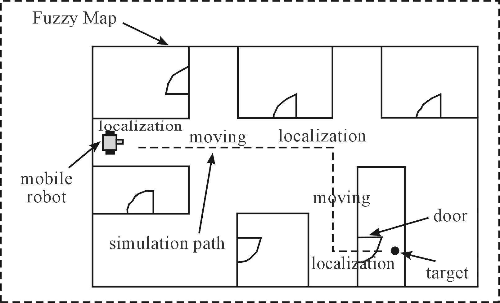
Fig.1 Mobile robot navigation process diagram.
In the physic experiment, JY901 module is fixed on the MT-R mobile robot platform to guarantee the module in the level state as much as possible. On the basis of the algorithm simulation validation, the development of corresponding software system is transplanted to MT-R hardware platforms. Mobile robot on indoor environment of rapid autonomous mobile robot localization algorithm would be verified, as the symbolic flowchart shown in Fig.2.
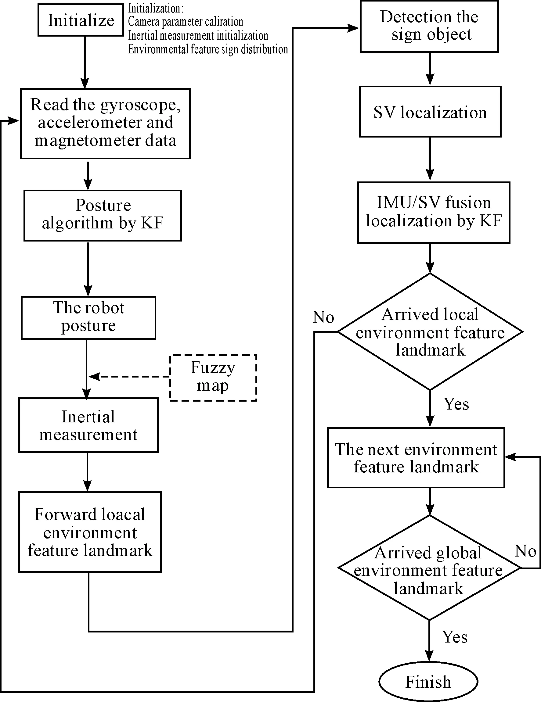
Fig.2 The flow chart of the software system.
2.2 Construction of indoor fuzzy map
The concept of indoor “Fuzzy Map” is set forth through some analysis. Indoor Fuzzy Map of environment around the mobile robot performs as a simplified map for task (an example in Fig.3). It mainly describes the environment important feature location (such as door, window, corner, etc.), which are the environment feature location, such as the distribution of the landmark, the topology of the turning points, internal map for mobile robot with proportioning of indoor environment map. Internal map for mobile robot is with proportioning of indoor environment map. And the feature of the location distribution known multiple coordinates was landmarks, it is completed that in the fuzzy map to blur the mobile robot in its environment. These 3d coordinate of environmental feature landmark were recorded when the mobile robot in the environment identified landmarks. By the distance solved from the center of the target, the vision location of mobile robot can be worked out combined with Fuzzy Map.
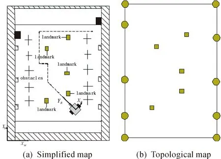
Fig.3 Indoor fuzzy map.
2.3 Stereo vision localization
In this section, stereo vision consists of two parts: identifying and locating. Because the environment feature landmarks used in the experiments in this paper are QR code, the recognition of QR code and stereo vision will be introduced.
2.3.1 QR code recognition
QR code is a special pattern which consists of a series of black and white small blocks as any combination of the formation, these black and white blocks represent binary numbers 0 and 1 respectively, different QR represents different binary strings. So QR code recognition has better uniqueness. QR code recognition steps are as follows.
Firstly, use the OSTU[15]algorithm to binarize the grayscale image. The OSTU algorithm principle is as follows:

q1(t)q2(t)[u1(t)-u2(t)]2
(1)

Secondly, find the image and positioning graphics of QR code images. The image and positioning graphics with black and white block width ratio are black∶white∶black∶white∶black=1∶ 1∶ 3∶ 1∶ 1. When detect the corners of QR code from left to right, from top to bottom, we can get the length of white and black blocks, the graphics that match the scale are the image and the positioning graphics. Sampling grid can be established according to the center of the image and positioning graphics, and the images will be converted into a data matrix.
Lastly, black and white blocks are determined according to the segmentation threshold in sampling grid. As mentioned above, the black block represents 1 and the white block represents 0, therefore, we can obtain the binary string corresponding to the QR code, so that QR code information will be obtained, such as the pixel of the center point in QR code in the horizontal direction of the image.
2.3.2 Stereo vision localization
The binocular distance model is based on the pattern of the retina imaging of the human eye. The relative distance between the observing point in the navigation frame and the model of the binocular camera is calculated by using the left and right camera imaging parallax[16].The stereo vision model is shown in Fig.4.
Any point in the binocular camera imaging process is vertical to the cross-section as shown in Fig.5. The principle of binocular distance measurement is the use of any three-dimensional space in the left and right camera imaging images on the horizontal coordinates of the difference (disparityd=Xleft-Xright). The parallax is inversely proportional to the distance between the plane and the point at which the camera is imaged[17]whereXleftandXrightare the pixel values in the horizontal direction of the target point (the center point in QR code) in the left and right camera image coordinate systems, respectively.

(2)
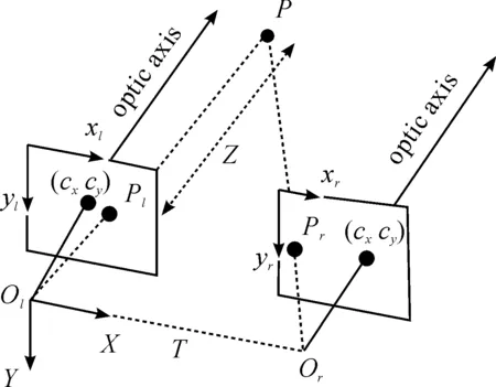
Fig.4 Stereo vision model.
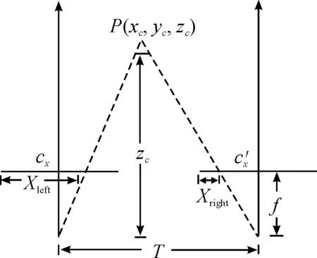
Fig.5 Stereo camera section.

(3)
In the three-dimensional reconstruction of an object, the homogeneous linear relationship between the pixel coordinates and the navigation coordinates is shown in the following formula (4),Yleftis the pixel value of the target point in the vertical direction of the left camera image.
(4)
Through (3) and (4) the target point of the navigation coordinatesX/W,Y/W,Z/Wcan be obtained. In order to obtain theQ, preparatory work such as calibration for binocular camera needs to be done. The calibration of internal and external parameters of binocular is carried out using the checkerboard method.
2.4 Fusion localization algorithm
The basic mechanism of localization and navigation is explained above for combining IMU and stereo vision. The following analysis will focus on the DKF algorithm of inertial measurement and binocular stereo vision localization fusion algorithm implementation process. In the indoor Fuzzy Map, the first mobile robot locates by the inertial measurement module. Combined with the current robot location and environment feature local landmark, by IMU, the robot parameters are converted into the robot motor control and mobile robot moves to the environment feature local location. Then mobile robot uses stereo vision to locate and fuse inertial measurement location by KF algorithm to ensure the robot navigation smoothly to the global target.
2.4.1 Inertial measurement posture algorithm
Posture decoding algorithm is one of the key technology to realize precise localization and navigation in inertial measurement system. The quaternion vector posture algorithm has the effectiveness and correctness[18,19]. The robot’s posture changes anytime in the operation. In order to measure the robot posture angle (φ,θ,φ), it is raised to use the quaternion to solve the robot posture in this paper. According to the quaternion differential equation:
(5)
Then available quaternion differential equations can be described as follows:
(6)
In the equation (5)wcan be defined as follows:
(7)
In order to facilitate solving, we utilize the differential equation of first order Runge - Kutta numerical methods to solve the quaternion differential:

(8)
If equations (6) and (8) are comprehensive, we can obtain available quaternion iterative relationship:
(9)

VB=q*VEq
(10)
The quaternion representation of the coordinate transformation matrix can be calculated as above:
(11)
The coordinate transformation matrix is expressed according to Euler angle as equation (12) fors,care marks for sin, cos respectively[10].
(12)
(13)
Due to the accumulated error of gyroscope, the coordinate transformation matrix and the robot posture will spread over time. In order to make the Euler angle state convergent, the observation on solving the amount can be used for KF processing which can make the posture angle of robot have convergence. Equation (14) is the state equation defines in KF process, and its observation equation is as equation (15):
Xk=Ak,k-1Xk-1+τk,k-1Wk-1
(14)
Zk=HkXk+Vk
(15)
The five basic equations of KF are as follows:

(17)
By acceleration compute posture angle and inverse solution of the quaternion, which consists of observation equation gravitational acceleration value in the inertial navigation system and the body coordinates has transformation relations as equation (18):
(18)
Expand the equation (15), It can be obtained:
(19)
For magnetometer yaw angle calculation, the magnetometer should rotate to the horizontal plane, namely.
(20)
Then the two expressions can be put into the equation (21) asHB=[HxHyHz]TandHE=[HExHEyHEz]T.

(21)
By equations(19), (21) the true quaternion can be work out:
(22)
Therefore, the mobile robot quaternion can be built as the observation equationZk=[q0,q1,q2,q3] for itsH(k)=I. After obtaining the state equation and observation equation, we can put the quantity of state and quantity of observation into five equations of KF and real-time to update posture of the mobile robot.
2.4.2 Inertial measurement localization algorithm
Through KF algorithm to fuse 9 axis sensor data, the robot’s posture can be calculated. Then it becomes convenient to convert the value of the accelerometer in navigation location calculation under the navigation system. Equation (23) describes the conversion relationship between them:
(23)
On one hand, integral calculation from the accelerometer of navigation coordinates is finished to produce mobile robot instantaneous velocity estimation, on the other hand, the instantaneous velocity integral calculation is finished to produce the instantaneous location of the mobile robot, the implementation process is as shown in Fig.6. The accelerometer and gyroscope data can be calculated through the integration of the navigation of mobile robot’s location and velocity in the navigation system. At the same time, the coordinate transformation, gestures calculation and the data average filtering processing for mobile robot can reduce the nonlinear location error of the drift of sensor devices data, and the accumulated error of gyroscope is reduced by Kalman fusion accelerometer and magnetometer information. Under the inertial measurement system at the same time, the local characteristics of mobile robot based on Fuzzy Map location area, the mobile robot and the distance from the center of the local feature vector is converted into a mobile robot control, and navigation of mobile robot moves rapidly to the local characteristics of the location area.
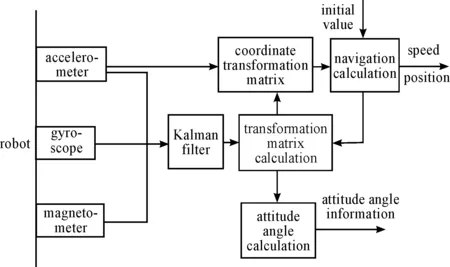
Fig.6 The principle diagram of the inertial measurement system.

(24)
2.4.3 Fusion localization algorithm by IMU/SV
In the paper, inertial measurement localization technology implementation process is analyzed. After getting the acceleration value of the mobile robot, through integral algorithm, the sensor output frequency as integral cycle, inertial measurement location of the mobile robot can be acquired at any time. However, the accelerometer values will be affected by outside noise interference, leading to the location of the accumulated over time. If the error isn’t amended, the mobile robot will go bad and becomes uncontrollable after a period of time. In order to solve such problems, the fusion between inertial measurement localization and stereo visual localization can be realized by KF algorithm, and the location error of the mobile robot can be reduced to some degree.
When the mobile robot moves to environment feature location landmark, the robot can use the stereo vision to locate the landmark in the environment. At the same time, the distance between robot and local landmark can be calculated based on stereo vision mobile robot location algorithm. By solving robot altitude, the angle of real-time 3d distance information can be converted to the world coordinate system.
As is shown in Fig.7, it is assuming that theφis the robot’s heading angle. Under the robot camera coordinate system, the coordinates of the target in the robot camera coordinate system are defined as (xc,yc,zc). Considering the robot in the horizontal plane, vertical informationyccan be ignored. According to the geometric relationship, equations (25) can be obtained,where (xE,yE) is the location information of the robot under navigation coordinate system:
(25)

(26)
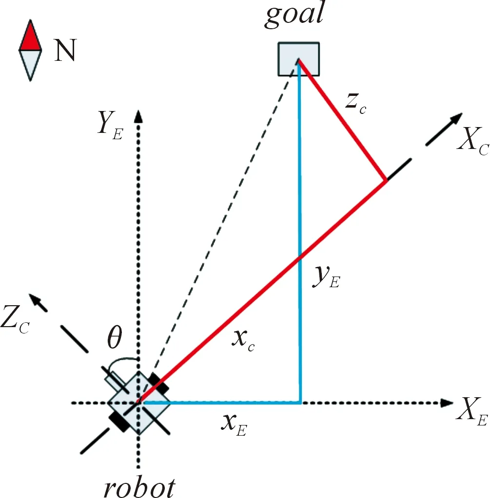
Fig.7 Locate relationship of stereo vision.
3 Demonstration
After the series of theoretical analysis, according to the inertial measurement and the needs of the stereo vision navigation scheme and algorithm implementation process, we carry out the following simulation and physical experiment to verify the effectiveness of the robot localization and navigation using inertial measurement and the stereo vision under complicated indoor environment. This paper focuses on the realization of fusion algorithm, inertial navigation is the main, the stereo vision is as a supplement, therefore, the following experiments aim to compare fusion experiments with inertial navigation experiments.
3.1 Simulation results
Through transformation matrix, acceleration value from JY901 module can be converted into the navigation system, the numerical can be imported by Matlab simulation platform to pass the low-pass filter for separation gravity acceleration value. Then the inertial measurement and posture algorithm are simulated (The acceleration value as shown in Fig.8.). The red curve represents the acceleration value of carrier system, and the blue curve represents the acceleration value of navigation system. It can be analyzed that the transition matrix for the unit matrix and the acceleration before and after the transformation were similar because the JY901 module keeps approximate linear motion, without horizontal rotation phenomenon. Besides it doesn’t produce acceleration in the vertical direction, so the acceleration value approximation is zero, namely.
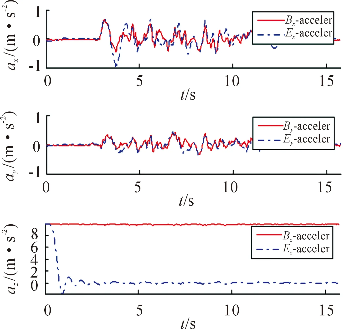
Fig.8 Recovered robot’s acceleration plotted at 10 samples per second.
Fig.9 is robot’s altitude angle (top) calculated by quaternion in the robot’s movement, for blue curve for the robot’s heading angle. Because of the horizontal plane motion of the robot, roll angle and pitching angle are close to zero, as shown in figure curve of red and green curve. The robot only changes in the yaw angle, the change for the green curve. Robot’s velocity (bottom) shows the robot of the speed change of the east and north in the process of movement.
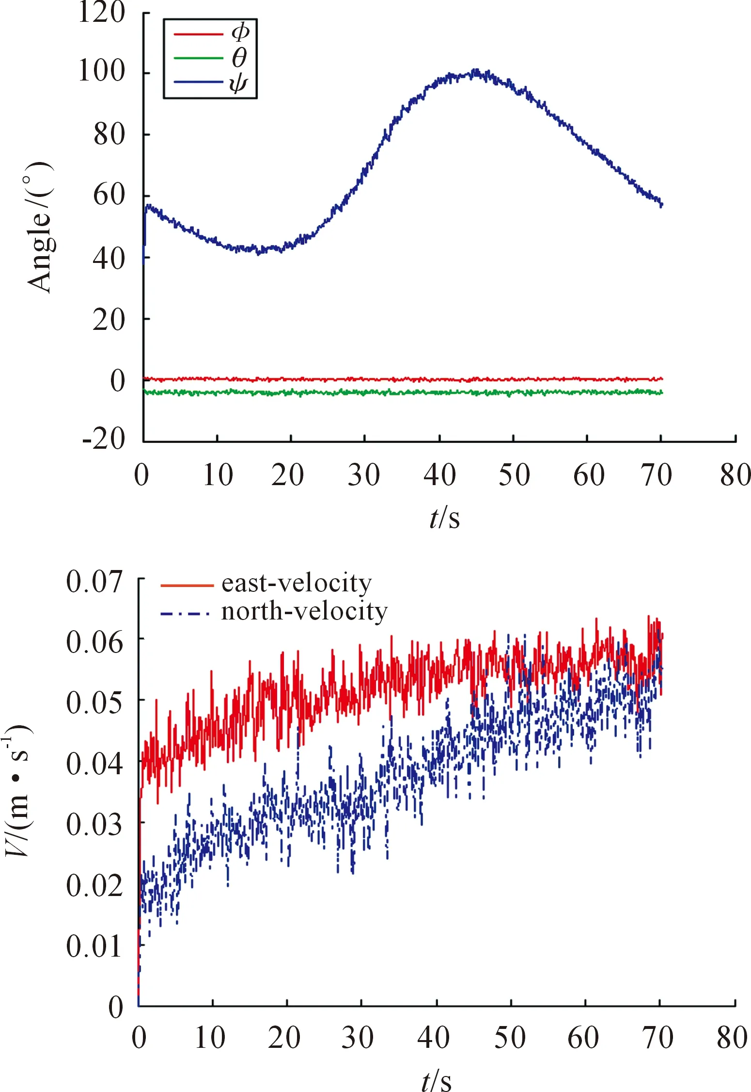
Fig.9 Recovered robot attitude angle (top) and velocity (bottom) plotted at 10 samples per second.
Fig.10 describes the robot’s navigation location. The black curve shows the true path of the robot measured by manual operation. The red curve, green curve is calculated path using IMU localization technology and IMU/SV fusion localization technology. As is shown in Fig.10, the path using IMU/SV fusion localization technology is more closer to the real path than that using the IMU localization technology.
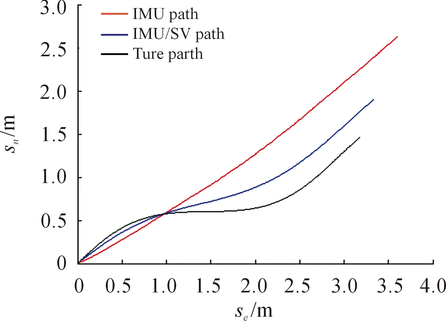
Fig.10 Recovered robot’s location plotted at 10 samples per second.
It is common to quantify the robot localization location performance as the static and dynamicRMS(Root-Mean-Square) errors in the robot localization parameters describing the east displacementSeand north displacementSnrespectively. Corresponding to the calibrated measurements of location, the IMU localization is estimated and the proposed IMU/SV fusion localization is estimated. The errors of estimated location parametersSe,Snwere computed as the difference between estimated values and the calibrated measurement. Results were obtained for a sequence of data about robot motionless and movement in indoor environment. The static and dynamicRMSerror of IMU localization and proposed IMU/SV fusion localization implementation is in Table 1.
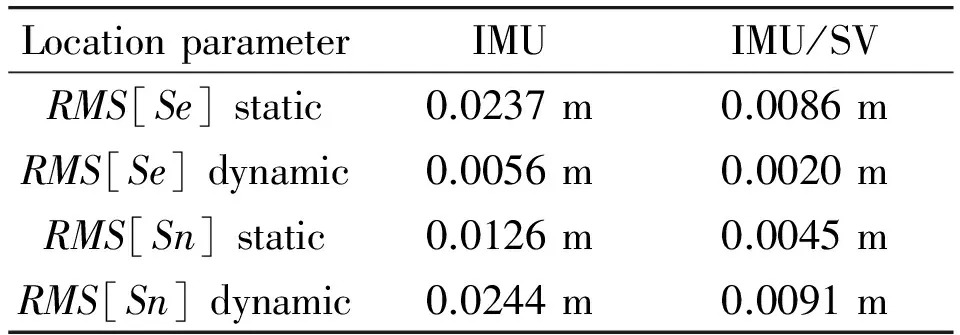
Table 1 Static and dynamic RMS error of IMU localization technology and proposed IMU/SV fusion localization technology.
The results of the dynamicRMSvalues ofSe,Snare summarized in Fig.11. It can be discovered that maxRMS[Se] value <0.4 m calculated by IMU localization technology and <0.2 m calculated by IMU/SV fusion localization technology while maxRMS[Sn] value<1 m calculated by IMU localization technology and <0.5 m calculated by IMU/SV fusion localization technology in dynamic environment.
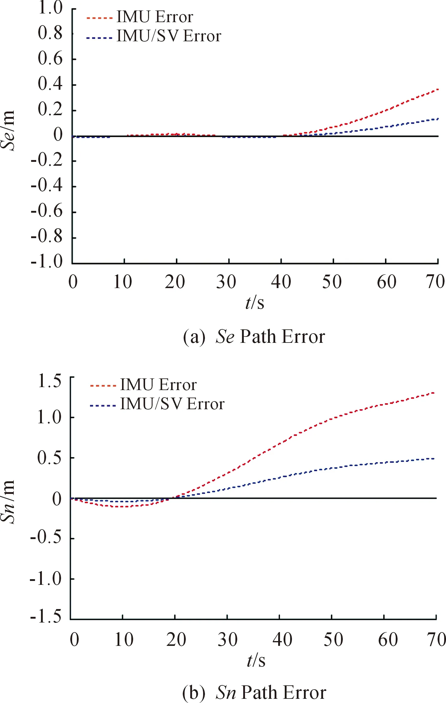
Fig.11 Typical results for measured and estimated location error in east (top) and in north (bottom).
3.2 Physical results
The proposed algorithm is tested on the MT-R mobile robot as shown in Fig.12. It includes JY901 inertial measurement module containing tri-axis gyroscopes, accelerometers and magnetometers and bumblebee2 camera containing depth of circumstance. Sensor data is logged to a PC at 512 Hz and imports accompanying software to provide the calibrated sensor measurements which are processed by the proposed DKF algorithm. The stereo camera provides SV information for robot to fuzz IMU location. Through fusing gyroscopes, accelerometers and magnetometers based on KF algorithm, the robot can get IMU location in navigation coordinate. As both the IMU algorithm and proposed DKF for IMU/SV were computed using identical sensor data, the performance of each algorithm could be evaluated relative to one another, independent of the sensor performance. A vision localization system consisting of two-dimensional location was used to provide reference measurements of the actual path. To do so, the JY901 module was fixed to the center of mobile platform and its orientation and the axial of the robot coincide. In order for the measurements of the robot location in navigation, the coordinate stereo camera was required where its data was logged to a PC at 10 Hz using visual location and IMU location fusion to get the best robot location.
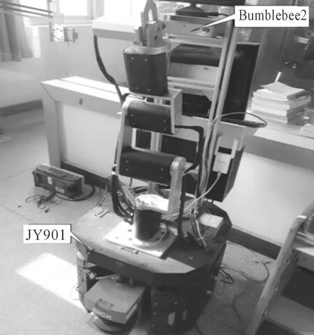
Fig.12 MT-R mobile robot.
Mobile robot localization system based on machine stereo vision is introduced above. The visual localization system is aimed at the environment feature landmark localization. The recognition of sign is not the focus of this article. By contrast, the recognition of QR code is better for its average of the recognition of color, shape and texture, etc, because the QR code identification has a higher recognition rate, rotation invariance, high stability and other features. Therefore, this physical experiment chooses the QR code as environment feature sign recognition, experiment put 7 pieces of pictures of different QR code for robot vision recognition and localization, at the same time. In order to guarantee the robot’s observe at any time in corporation, the QR code image and bumblebee2 are roughly put in the same height. The construction of the metric QR codes position is set hand by hand while the absolute coordinates of 7 pieces of pictures of the QR code in the laboratory are shown in table 2.
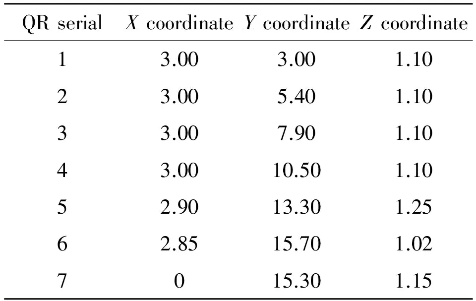
Table 2 QR code coordinate distribution (Unit: m).
The system consists of a serial port turn USB module to collect sensor data, and uses the Kalman fusion accelerometer and gyroscope and magnetometer to calculate the attitude angle of the robot. At the same time, the airborne acceleration value is converted to a value under the navigation system for calculating the location of the robot by the navigation algorithm. When the mobile robot arrives at the location in distribution of the indoor environment feature landmark near QR code(the QR code distribution as shown in Fig.13). Stereo visual location can be obtained through the bumblebee2. At this time, the mobile robot again fuses inertial measurement location and machine visual location based Kalman filter algorithm to acquire optimization location of the mobile robot. It will be real-time display on the mobile robot PC interface.
In this paper, the physical experiment site 602 laboratory of Wuhan University of Science and Technology information institute of science and engineering, for the convenience of description, the following data units are in meters, the robot’s initial location is set as (0,0) while final location as (0,15.5). Through simulating, the robot’s motion path curve of blue is as shown in Fig.11. Experiments with the speed of the mobile robot by the initial location (0,0) to the first QR code security target moving along a straight line (3.2,3.2), which sets the mobile robot safety campaign radius of 0.2 m. Therefore the angle between initial point and end point can be calculated by 45° and the angle of the measured laboratory toward the north by east is 60°. Through the above, two calculation can make the direction of the mobile robot for 105° north by east, gesture decoding algorithm can be used to get the rotate angle of mobile robot, the advancing angle difference can get required rotation attitude angle of mobile robot. Then the mobile robot would be forwards to point of view by controlling chassis selection to the corresponding while the mobile robot would be gone in a rectilinear motion. At the same time the IMU location can be calculated by the inertial measurement module in the movement. When the distance of the QR code distance is less than 0.2 m, the mobile will stop and bumblebee2 module operates immediately, with recognition of QR code and calculation 3d distance information. At the same time, according to the known QR code location in fuzzy map, it will be out of using the visual localization. By KF fusion with inertial measurement location, the true location of the mobile robot can be obtained. Similarly, in the process of the experiment of mobile robot in the location (3.2,3.2), (3.2,5.5), (3.2,8.0), (3.3,10.5), (3.1,13.5), (3.2,16.0) and (0.0,15.5) respectively to locate. MT-R mobile robot navigation software in the red line shows the MT-R walking the path of the mobile robot, the following mainly records the MT-R mobile robot in QR code, the state of the mobile robot updates the location as shown in Fig.14.
This experiment records the location data of mobile robot in Matlab to draw out as shown in Fig.15. The red solid line for the real path of mobile robot, the blue dotted line for different path for mobile robot localization algorithm to calculate, it is obvious that the use of IMU/MV fusion localization for mobile robot path (as shown in Fig.15a) than the use of IMU localization is closer to the real path of mobile robot (as shown in Fig.15b), and the experimental results show that the proposed dual mechanism of Kalman filtering fusion algorithm of inertial navigation and stereo vision measurement on mobile robot indoor localization accuracy is effective.

Fig.13 QR code distribution.
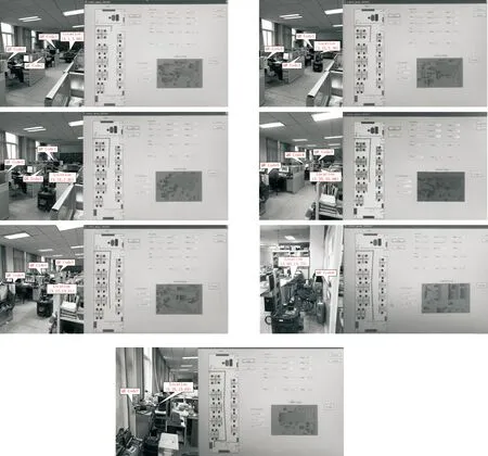
Fig.14 The diagram of mobile robot localization experiment.
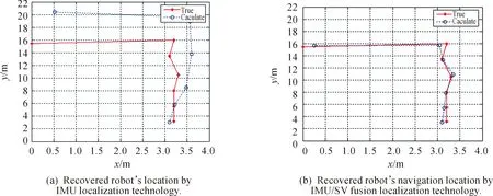
Fig.15 Localization accuracy of the mobile robot.
4 Conclusion and Future Work
As can be seen from the experiment, using inertial measurement and binocular stereo vision for mobile robot localization technology is feasible. Dual Kalman filtering mechanism was introduced to improve the localization accuracy. First, high precision location information of mobile robot can be obtained by using fusing Kalman filter algorithm of accelerometer, gyroscope and magnetometer data. Secondly, inertial measurement precision can be optimized by using Kalman filtering algorithm combined with machine vision localization algorithm. This method has good real-time performance and precision, the maxRMSvalue < 0.5 m.
Acknowledgment
This work is supported by four Projects from National Natural Science Foundation of China (60705035, 61075087, 61573263, 61273188), Scientific Research Plan Key Project of Hubei Provincial Department of Education (D20131105), Project supported by the Zhejiang Open Foundation of the Most Important Subjects, and supported by Science and Technology support plan of Hubei Province (2015BAA018), also supported by Zhejiang Provincial Natural Science Foundation (LY16F030007) and Sub-topics of National Key Research project(2017YFC0806503).
[1]M.Y.Cui, Z.L.Dong, and Y.T.Tian, Laser global positioning system (GPS) algorithm of mobile robot research,JournalofSystemsEngineeringandElectronics, vo.24, no.11, pp.73-75, 2001.
[2]X.H.Wang,IndoorLocatingMethodBasedonBluetoothWirelessTechnologyResearch. Zhejiang: zhejiang university of technology signal and information processing, 2007.
[3]C.Wu, B.Su, X.Q.Jiao, and X.Wang, Research on WIFI Indoor Positioning Based on Improved Dynamic RSSI Algorithm,JournalofChangzhouUniversity, vol.26, no.1, pp.32-36, 2014.
[4]Y.Ni and J.Dai, ZigBee positioning technology research,JournalofNanjingIndustryProfessionalTechnologyInstitute, vol.13, no.2, pp.43-45, 2013.
[5]J.Wu, H.M.D.Abdulla, and V.Snasel, Application of Binocular Vision and Diamond Search Technology in Computer Vision Navigation, inProceedingsof2009InternationalConferenceonIntelligentNetworkingandCollaborativeSystems, 2009, pp.87-92.
[6]Z.Liu, W.H.Chen, Y.H.Zou, and X.M.Wu, Salient Region Detection Based on Binocular Vision, inProceedingsof2012IEEEInternationalConferenceonIndustrialElectronicsandApplications(ICIEA), 2012, pp.1862-1866.
[7]R.Xiang, H.Y.Jiang, and Y.B.Ying, Recognition of clustered tomatoes based on binocular stereo vision,ComputersandElectronicsinAgriculture, vol.106, pp.75-90, 2014.
[8]S.Nefti-Meziani, U.Manzoor, S.Davis, and S.K.Pupala, 3D perception from binocular vision for a low cost humanoid robot NAO,RoboticsandAutonomousSystems, vol.68, pp.129-139, 2015.
[9]J.Jiang, J.Cheng, and H.F.Zhao, Stereo Matching Based on Random Speckle Projection for Dynamic 3D Sensing, inProceedingsof2012InternationalConferenceonMachineLearningandApplications, 2012, pp.191-196.
[10] H.Wu, Y.Cai, and S.J.Ren, Substation robot binocular vision navigation stereo matching method,Journalofdigitaltechnologyandapplication, vol.12, pp.59-60, 2011.
[11] P.J.Lin, Y.Chu, S.Y.Cheng, J.Zhang, and S.L.Lai, Autonomous Navigation System Based on Binocular Stereo Vision,JournalofFujianNormalUniversity, vol.30, no.6, pp.27-32, 2014.
[12] S.Sukkarieh, E.M.Nebot, and H.F.Durrant-Whyte, A High Integrity IMU/GPS Navigation Loop for Autonomous Land Vehicle Applications,RoboticsandAutomation, vol.15, no.3, pp.572-578, 1999.
[13] D.Y.Wang, X.G.Huang, and Y.F.Guan Y F, Based on the innovative marketing with measurement correction of lunar soft landing autonomous navigation research,JournalofAstronautics, vol.28, no.6, pp.1544-1549, 2007.
[14] Y.J.Yu, J.F.Xu, and L.Zhang L, Inertial navigation/binocular vision pose estimation algorithm research,ChineseJournalofScientificInstrument, vol.35, no.10, pp.2170-2174, 2014.
[15] W.H.Wang, Y.H.Zhang, Q.Y.Zhu, and J.S.Shan, Image Recognition in 2-D Bar Code Based on QR Code.ComputerTechnologyandDevelopment, vol.19, no.10, pp.123-126, 2009.
[16] Y.J.Zhang, Y.Pan, and C.Wu, Based on the vehicle-based system of CCD camera measurement,InformationSecurityandTechnology, no.1, pp.57-62, 2016.
[17] J.X.Liu,TheResearchofTheCameraCalibrationandStereoscopicMatchingTechnique.Guangzhou: Guangdong University of Technology, 2012.
[18] R.H.Zhang, H.G.Jia, T.Chen, and Y.Zhang, Attitude solution for strapdown inertial navigation system based on quaternion algorithm,Optics&PrecisionEngineeringno.10, pp.1963-1970, 2008.
[19] S.Q.Zhang and Y.W.Zhao, Portable mobile robot posture calculating method,MicrocomputerInformation, no.29, pp.188-189, 2007.
[20] B.N.Saeed,Unmannedaerialvehicle(uav)introduction,analysis,systemsandapplications.Beijing: Electronic Industry Press, 2004.
 CAAI Transactions on Intelligence Technology2017年4期
- CAAI Transactions on Intelligence Technology的其它文章
- A Lane Detection Algorithm Based on Temporal-Spatial Information Matching and Fusion
- Proposal of Initiative Service Model for Service Robot
- Visual Navigation Method for Indoor Mobile Robot Based on Extended BoW Model
- Diagnosis System for Parkinson’s Disease Using Speech Characteristics of Patients and Deep Belief Network
- A Mixed Reality System for Industrial Environment: an Evaluation Study
- Magnetic Orientation System Based on Magnetometer, Accelerometer and Gyroscope
